EP0210330B1 - Procédé et appareil pour un système d'asservissement de piste suivant la wobulation composée - Google Patents
Procédé et appareil pour un système d'asservissement de piste suivant la wobulation composée Download PDFInfo
- Publication number
- EP0210330B1 EP0210330B1 EP86104340A EP86104340A EP0210330B1 EP 0210330 B1 EP0210330 B1 EP 0210330B1 EP 86104340 A EP86104340 A EP 86104340A EP 86104340 A EP86104340 A EP 86104340A EP 0210330 B1 EP0210330 B1 EP 0210330B1
- Authority
- EP
- European Patent Office
- Prior art keywords
- signal
- tracking error
- error signal
- tracking
- wobbled
- Prior art date
- Legal status (The legal status is an assumption and is not a legal conclusion. Google has not performed a legal analysis and makes no representation as to the accuracy of the status listed.)
- Expired
Links
- 238000000034 method Methods 0.000 title claims description 35
- 239000002131 composite material Substances 0.000 title claims description 12
- 206010028896 Needle track marks Diseases 0.000 claims description 29
- 230000003287 optical effect Effects 0.000 claims description 29
- 238000001514 detection method Methods 0.000 claims description 19
- 238000005070 sampling Methods 0.000 claims description 12
- 238000012937 correction Methods 0.000 claims description 6
- 230000035945 sensitivity Effects 0.000 claims description 6
- 230000001678 irradiating effect Effects 0.000 claims description 5
- 230000002159 abnormal effect Effects 0.000 claims description 2
- 238000003909 pattern recognition Methods 0.000 claims 4
- 230000004044 response Effects 0.000 claims 2
- 238000010586 diagram Methods 0.000 description 18
- 238000009826 distribution Methods 0.000 description 17
- 231100000241 scar Toxicity 0.000 description 5
- 239000004065 semiconductor Substances 0.000 description 4
- 230000009977 dual effect Effects 0.000 description 3
- 239000000463 material Substances 0.000 description 3
- 230000010076 replication Effects 0.000 description 3
- 230000009471 action Effects 0.000 description 2
- 230000007547 defect Effects 0.000 description 2
- 238000002360 preparation method Methods 0.000 description 2
- 230000008859 change Effects 0.000 description 1
- 150000001875 compounds Chemical class 0.000 description 1
- 230000008878 coupling Effects 0.000 description 1
- 238000010168 coupling process Methods 0.000 description 1
- 238000005859 coupling reaction Methods 0.000 description 1
- 230000002950 deficient Effects 0.000 description 1
- 238000002050 diffraction method Methods 0.000 description 1
- 239000000428 dust Substances 0.000 description 1
- 230000006870 function Effects 0.000 description 1
- 238000004519 manufacturing process Methods 0.000 description 1
- 230000004048 modification Effects 0.000 description 1
- 238000012986 modification Methods 0.000 description 1
- 230000008569 process Effects 0.000 description 1
- 238000011160 research Methods 0.000 description 1
- 239000000758 substrate Substances 0.000 description 1
- 230000001629 suppression Effects 0.000 description 1
- 230000001360 synchronised effect Effects 0.000 description 1
- 238000012546 transfer Methods 0.000 description 1
Images





Classifications
-
- G—PHYSICS
- G11—INFORMATION STORAGE
- G11B—INFORMATION STORAGE BASED ON RELATIVE MOVEMENT BETWEEN RECORD CARRIER AND TRANSDUCER
- G11B7/00—Recording or reproducing by optical means, e.g. recording using a thermal beam of optical radiation by modifying optical properties or the physical structure, reproducing using an optical beam at lower power by sensing optical properties; Record carriers therefor
- G11B7/24—Record carriers characterised by shape, structure or physical properties, or by the selection of the material
- G11B7/2407—Tracks or pits; Shape, structure or physical properties thereof
- G11B7/24085—Pits
-
- G—PHYSICS
- G11—INFORMATION STORAGE
- G11B—INFORMATION STORAGE BASED ON RELATIVE MOVEMENT BETWEEN RECORD CARRIER AND TRANSDUCER
- G11B7/00—Recording or reproducing by optical means, e.g. recording using a thermal beam of optical radiation by modifying optical properties or the physical structure, reproducing using an optical beam at lower power by sensing optical properties; Record carriers therefor
- G11B7/08—Disposition or mounting of heads or light sources relatively to record carriers
- G11B7/09—Disposition or mounting of heads or light sources relatively to record carriers with provision for moving the light beam or focus plane for the purpose of maintaining alignment of the light beam relative to the record carrier during transducing operation, e.g. to compensate for surface irregularities of the latter or for track following
- G11B7/094—Methods and circuits for servo offset compensation
-
- G—PHYSICS
- G11—INFORMATION STORAGE
- G11B—INFORMATION STORAGE BASED ON RELATIVE MOVEMENT BETWEEN RECORD CARRIER AND TRANSDUCER
- G11B7/00—Recording or reproducing by optical means, e.g. recording using a thermal beam of optical radiation by modifying optical properties or the physical structure, reproducing using an optical beam at lower power by sensing optical properties; Record carriers therefor
- G11B7/08—Disposition or mounting of heads or light sources relatively to record carriers
- G11B7/09—Disposition or mounting of heads or light sources relatively to record carriers with provision for moving the light beam or focus plane for the purpose of maintaining alignment of the light beam relative to the record carrier during transducing operation, e.g. to compensate for surface irregularities of the latter or for track following
- G11B7/0948—Disposition or mounting of heads or light sources relatively to record carriers with provision for moving the light beam or focus plane for the purpose of maintaining alignment of the light beam relative to the record carrier during transducing operation, e.g. to compensate for surface irregularities of the latter or for track following specially adapted for detection and avoidance or compensation of imperfections on the carrier, e.g. dust, scratches, dropouts
-
- G—PHYSICS
- G11—INFORMATION STORAGE
- G11B—INFORMATION STORAGE BASED ON RELATIVE MOVEMENT BETWEEN RECORD CARRIER AND TRANSDUCER
- G11B7/00—Recording or reproducing by optical means, e.g. recording using a thermal beam of optical radiation by modifying optical properties or the physical structure, reproducing using an optical beam at lower power by sensing optical properties; Record carriers therefor
- G11B7/08—Disposition or mounting of heads or light sources relatively to record carriers
- G11B7/09—Disposition or mounting of heads or light sources relatively to record carriers with provision for moving the light beam or focus plane for the purpose of maintaining alignment of the light beam relative to the record carrier during transducing operation, e.g. to compensate for surface irregularities of the latter or for track following
- G11B7/095—Disposition or mounting of heads or light sources relatively to record carriers with provision for moving the light beam or focus plane for the purpose of maintaining alignment of the light beam relative to the record carrier during transducing operation, e.g. to compensate for surface irregularities of the latter or for track following specially adapted for discs, e.g. for compensation of eccentricity or wobble
- G11B7/0956—Disposition or mounting of heads or light sources relatively to record carriers with provision for moving the light beam or focus plane for the purpose of maintaining alignment of the light beam relative to the record carrier during transducing operation, e.g. to compensate for surface irregularities of the latter or for track following specially adapted for discs, e.g. for compensation of eccentricity or wobble to compensate for tilt, skew, warp or inclination of the disc, i.e. maintain the optical axis at right angles to the disc
-
- G—PHYSICS
- G11—INFORMATION STORAGE
- G11B—INFORMATION STORAGE BASED ON RELATIVE MOVEMENT BETWEEN RECORD CARRIER AND TRANSDUCER
- G11B7/00—Recording or reproducing by optical means, e.g. recording using a thermal beam of optical radiation by modifying optical properties or the physical structure, reproducing using an optical beam at lower power by sensing optical properties; Record carriers therefor
- G11B7/08—Disposition or mounting of heads or light sources relatively to record carriers
- G11B7/09—Disposition or mounting of heads or light sources relatively to record carriers with provision for moving the light beam or focus plane for the purpose of maintaining alignment of the light beam relative to the record carrier during transducing operation, e.g. to compensate for surface irregularities of the latter or for track following
- G11B7/0901—Disposition or mounting of heads or light sources relatively to record carriers with provision for moving the light beam or focus plane for the purpose of maintaining alignment of the light beam relative to the record carrier during transducing operation, e.g. to compensate for surface irregularities of the latter or for track following for track following only
- G11B7/0904—Dithered tracking systems
Definitions
- This invention relates to a tracking servo system for tracking the center of a track with a light spot, and more particularly to a composite tracking servo system in which a differential diffraction method using pregrooves or a so-called push-pull tracking method is combined with a wobbled tracking method using wobbled track marks disposed in a relation wobbled relative to the center of a track, and which is suitable for application to an optical code data memory such as a recordable/reproducible adding type optical disc system or an erasable type optical disc system
- an optical disc having guide grooves or so-called pregrooves formed previously along the direction of rotation of the disc is irradiated with a light spot, and an unbalance of the distribution of the reflection of light diffracted from the pregrooves is based to detect a track error which is fed back to a servo system.
- This push-pull tracking method is disclosed in, for example, U.S. Patent No. 4,363,116. Since this push-pull tracking method utilizes the distribution of the reflection of light diffracted from the pregrooves, an offset attributable to an eccentricity or tilt of the disc tends to occur, and, because of such an offset, the light spot cannot be accurately positioned on the center of the track. According to the researches made by the inventors, a tilt of 0.7° or an eccentricity of 100 wm, for example, results in an offset of about 0.1 1 gm.
- a tracking servo system of three spots type is widely employed in a playback-only system such as a CD (a compact disc).
- a CD compact disc
- this tracking servo system is unfit for application to a combined recording/reproduction system.
- the tracking servo system of three spots type is disclosed in, for example, U.S. Patent No. 3 876 842.
- the present invention utilizes the so-called track wobbling method in which an optical disc is previously formed with one or more sets of wobbled pits disposed in a relation wobbled relative to the center of a track, and the relative amounts of light reflected after being passed through these pits as a result of irradiation with a light spot are compared to detect a track error, if any.
- This track wobbling method is already known per se and disclosed in, for example, U.S. Patent No. 4,223,187.
- the true position of light spot passed through the wobbled pits can be detected. Therefore, a more accurate servo system can be provided as compared to a servo system utilizing the push-pull method based on the distribution of diffraction by the pregrooves.
- the track wobbling method requires provision of 1,000 or more wobbled pits per track, resulting in a corresponding by reduced data efficiency.
- the track wobbling method has such another problem that it is not compatible with the push-pull method.
- the present invention provides a tracking system of high utility which has such features that (1) the merit of the wobbled tracking method is maintained; (2) the data efficiency is not degraded; and (3) it is compatible with the push-pull tracking system which is a prior art system most widely employed in this field.
- the tracking servo system according to the present invention is a composite of the push-pull tracking system using the pregrooves and the wobbled tracking system using the wobbled track marks, and has a dual structure so that an offset of a low-frequency component from the dc level, which offset tends to occur in the push-pull servo system, can be suppressed in the wobbling servo system.
- one complete track on an optical disc is divided into a plurality of sectors each of which includes a header field (or an index field) perviously formed with pits and a data field on which the user records desired information.
- a header field or an index field
- wobbled track marks in the form of one or more pairs of elongate pits are previously formed in a relation wobbled relative to the center of the track, and pregrooves for tracking purpose are previously formed in at least the data field.
- the word "previously" as used herein means that the wobbled track marks and the pregrooves have been provided before the user records desired information on the data field.
- the wobbled track marks and the pregrooves which have been formed during preparation of a mother disc are provided by replication of the mother disc.
- address information for identifying the specific sector and a sector mark indicating the head of the specific sector are previously formed in the header field.
- the wobbled track mark may act also as the sector mark.
- a push-pull tracking error signal including an offset and utilizing the distribution of the reflection of light diffracted from the pregrooves is corrected on the basis of the prewobbling tracking error signal, thereby eliminating the offset attributable to deviation of the diffracted light beam on a light detector and ensuring stable and highly accurate tracking operation. While tracking in the manner described above, data are recorded on or reproduced from one of the pregrooves or a land between the pregroove and an adjacent pregroove.
- the tracking error signal detecting method according to the present invention is the combination of the prewobbling method and the push-pull method as described already. This detecting method will be first described.
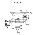
- Fig. 1 shows the structure of one form of an optical system for recording and reproducing information on and from an optical disc.
- semiconductor laser drive signals 1 and 2 are applied to a semiconductor laser driver circuit 3 to drive a semiconductor laser 4.
- Light emitted from the semiconductor laser 4 passes through a coupling lens 5, a beam splitter 6, a galva mirror 7, a 1/4 wavelength plate 8 and an opjective lens 9 to form a light spot 11 on a recording surface of an optical disc 10 thereby irradiating a track 12.
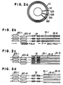
- Figs. 2a to 2d illustrate various examples of the structure of pregrooved tracks of a recordable/reproducible optical disc of the present invention adapted to be used in such an optical disc apparatus.
- one complete track 12 is divided into, for example, 64 sectors each of which includes a set of a header field 123 previously formed with pits and a data field 122 on which the user records desired information.
- a selected number of, or, for example, a pair of elongate pits (wobbled track marks) 20-1 and 20-2 wobbled relative to the track center are previously formed by replication, so as to detect a tracking error signal according to the prewobbling method.
- pits 14 indicative of a track address, a sector address, a synchronizing signal, etc. are formed along the track center without being arranged in a wobbled relation.
- these pits 14 are not necessarily essentially required in the tracking servo system of the present invention and may be omitted as required.
- the wobbled track marks 20-1 and 20-2 act also as sector marks indicating the head of the corresponding sector.
- these marks 20-1 and 20-2 may be disposed in any other position, for example, between the sector marks and the address signal prepits or in a gap area between the address signal prepits and the data field.
- the prepits (including the wobbled track marks) previously formed in the header field 123 are of phase structure having a depth which is 1/4 or 1/8 of the wavelength of the laser beam used for recording and reproduction of information on and from the data field 122.
- at least the pregrooves formed in the data field 122 are of phase structure having a depth which is 1/8 of the wavelength of the laser beam and are concentrically or spirally arranged.
- the track center registers with the center of the pregrooves 15-1 and 15-2, and data are recorded on these pregrooves.
- the pregrooves 15-1 and 15-2 may be formed in this area too.
- the track center registers with the centerline extending between the adjacent pregrooves 15-1 and 15-2, and data are recorded on a land 15-3 defined between the pregrooves 15-1 and 15-2.
- the pregrooves 15-1 and 15-2 may be formed at least in the data field 122. Further, as shown in Fig.
- the pregrooves 15-1 and 15-2 may also be formed to sandwich the prepits 14 therebetween in the area where the prepits 14 are formed in the header field 123. Further, the pregrooves 15-1 and 15-2 may be formed to sandwich the wobbled track marks 20-1 and 20-2 therebetween and may extend thoughout the header field 123 and data field 122 without any discontinuity.
- the aforementioned wobbled track marks, prepits and pregrooves are previously formed during preparation of a mother disc, and a disc substrate obtained by replication of the mother disc having the wobbled track marks, prepits and pregrooves previously formed thereon is coated with a desired recording film.
- a film of a material such as TeSePb, whose principal component is Te is preferably used as the recording film.
- a vertical magnetized film of a material such as TbFeCo, whose principal component is TbFe is preferably used as the recording film.
- a film of a material such as an amorphous Te compound is preferably used as the recording film.
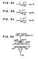
- Figs. 3a to 3d illustrate the distribution of diffract light on the two-divided light detector 13 (the light-receiving sections 131 and 132) when the light spot 11 directed onto the pregroove 15 of phase structure deviates from the center of the pregroove 15. Deviation of the light spot 11 from the center of the track results in an asymmetrical distribution of diffracted light. Therefore, when the diffracted light from the pregroove 15 is received by the two light receiving sections 131 and 132 disposed in parallel to the track to sandwich therebetween the track, and the difference between the output signals of the two light receiving sections 131 and 132 is found, a push-pull tracking error signal 16 can be detected as shown in Fig. 3d. Figs.
- 3a to 3c show the relation between the light spot 11 and the pregroove 15.
- An interference pattern between light of zeroth order and light of first order diffracted by the pregroove 15 appears on the two-divided light detector 13.
- this interference pattern is symmetrical with respect to the pregroove 15.
- the symmetry of the interference pattern is lost, and the differential output of the two-divided light detector 13 is not zero, so that the track error can be detected.
- This differential output of the light detector 13 is fed back to a tracking actuator, for example, the galva mirror 7 to constitute a tracking servo.
- the polarity of the differential output of the light detector 13 should be inverted before being fed back to the tracking actuator or galva mirror 7. That is, when the light spot 11 is directed toward or positioned on the land 15-3 between the pregrooves 15-1 and 15-2, the light spot 11 diverges over the two pregrooves 15-1 and 15-2, and the interference pattern due to diffraction appears on the light detector 13 as when the light spot 11 is centered on the pregroove 15.
- the light detector 13 is in no way limited to that of the two-divided type described above and may be of a three-divided type in which another light receiving section is interposed between a pair of light receiving sections for tracking purpose.
- the light detector has such a structure that at least two light detecting sections (light receiving sections) are disposed to sandwich the track therebetween in parallel to the extending direction of the track.
- An example of such a light detector detecting the track error, if any, on the basis of diffracted light from a pregroove is disclosed in, for example, U.S. Patent No. 4,525,826.
- Fig. 4 is a block diagram showing the structure of a push-pull tracking servo system based on the principle described with reference to Figs. 3a to 3d
- Fig. 5 is a Bode diagram of the loop transfer function of the servo system shown in Fig. 4.
- the servo system includes a tracking error detecting element (Kd) 17, a phase compensating element (Gc) 18, and a tracking actuator (Gd) 19.
- the so-called push-pull tracking system for obtaining the differential signal is indicative of the distribution of the reflection light diffracted from the pregroove 15, the galva mirror 7 is moved so that the light spot 11 can follow up, for example, eccentricity of the optical disc 10 shown in Fig.
- the diffracted light distribution on the light detector 13 shifts as shown in Fig. 3d.
- the shifting of the diffracted light distribution results in appearance of an offset in the tracking error signal 16.
- the diffract light distribution on the two light receiving sections 131 and 132 of the two-divided light detector 13 disposed in parallel to the track 12 is now out of balance, and such a phenomenon occurs in which the tracking error signal 16 does not become zero even when the light spot 11 is positioned on the track center (the center of the pregroove 15 or the center of the land 15-3), that is, a track offset occurs. Consequently, the light spot 11 cannot be accurately positioned on the track center.
- an offset-free prewobbling tracking error signal detected when the light spot 11 irradiates the prewobbling pits 20-1 and 20-2 in the header field 123 is utilized for offset correction of the push-pull tracking error signal 16 which includes the offset and which is detected when the light spot 11 irradiates the pregroove 15 disposed in the data field 122.
- the push-pull tracking error signal 16 while correcting the push-pull tracking error signal 16 on the basis of the offset-free prewobbling tracking error signal, data pits are accurately recorded and reproducted, with a high S/N ratio, on and from the pregroove 15 or inter-pregroove land 15-3.
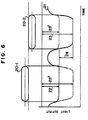
- Fig. 6 shows the arrangement of at least one pair of elongate pits 20-1 and 20-2 disposed in a relation wobbled relative to the track center so as to detect the prewobbling tracking error signal according to the present invention and shows also the relation between the passing position of the light spot 11 and the waveform of the light output.
- the light spot 11 irradiates the pair of wobbled track marks 20-1 and 20-2 while crossing them relative to time, an output signal 21 having a waveform as shown appears from the light detector 13 (the sum of the output signals of the light receiving sections 131 and 132). It will be seen in Fig.
- the light output signals relevant to the elongate pits 20-1 and 20-2 arranged in the relation wobbled relative to the track center have opposite polarities depending on the transverse deviation of the center of the light spot 11 from the track center. That is, when the light spot 11 traverses the portion nearer to the pit 20-1, the output signal 21 has a waveform as shown by the dotted line, while, when the light spot 11 traverses the portion nearer to the pit 20-2, the output signal 21 has a waveform inverted by 180 0 in phase, as shown by the solid line.
- this differential signal 24 indicates the amount and direction of deviation of the light spot 11 from the track center.
- the method of detecting the prewobbling tracking error signal 24 described with reference to Fig. 6 is not based on the diffracted light distribution. Therefore, a dc tracking offset attributable to tilting of the disk 10 or, for example, movement of the lens 9 or rotation of galva mirror 7 as a result of tracking control does not occur, so that the amount of the true tracking error can be accurately detected.
- the composite wobbled tracking servo system of the present invention can attain accurate tracking, since it comprises the combination of the two different tracking error detection methods, that is, the method of detecting the dc-offset-free tracking error signal 24 obtained from the prewobbling pits 20-1 and 20-2 shown in Fig. 6 and the method of detecting the dc-offset-including tracking error signal 16 obtained from the pregroove 15 shown in Figs. 3a to 3d.
- the basic block diagram of the servo system based on the pregroove method has been illustrated already in Fig. 4. Fundamentally, the servo system shown in Fig.
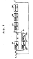
- Fig. 7 is a block diagram showing the structure of an embodiment of the composite wobbled tracking servo system according to the present invention.
- the tracking servo system of the present invention shown in Fig. 7 has a dual servo system structure including a push-pull loop and a wobbled loop.
- the push-pull loop includes a tracking error detecting element (Kd) 25 utilizing the pregrooves, phase compensating elements (G i ) 27 and (G 2 ) 29, and a tracking actuator (Ka) 30.
- the wobbled loop includes a tracking error detecting element (Kw) 26 utilizing the wobbled track marks, a low-pass filter (Fw) 28, and the common phase compensating elements, 27, 29 and the common tracking actuator 30 of the push-pull loop.
- This prewobbling tracking error signal 24 is an accurate servo signal free from any offset attributable to, for example, tilting of the disc 10. Therefore, this prewobbling tracking error signal 24 is suitable for controlling a low-frequency range of the servo system of Fig. 7.
- the prewobbling track error signal 24 is passed through the low-pass filter (Fw) 28 having a band-limiting filter characteristics as shown in Fig. 8, and a bandlimited servo signal 31 that can handle the servo action in the low-frequency range appears from the low-pass filter (Fw) 28.
- the method of signal detection is based on the diffracted light distribution. Therefore, this signal 16 includes a dc offset attributable to, for example, tilting of the disc 10, as described already.
- the pregroove tracking error signal 16 covers from a low-frequency range to a high-frequency range as shown in Fig. 8.
- the prewobbling tracking error signal 31 of the high gain band-limited by the low-pass filter (Fw) 28 in the manner described above and the push-pull tracking error signal 16 of low gain are added in an adder circuit 32 as shown in Fig. 7, and the resultant tracking error signal 33 is phase-compensated by the phase compensating circuits (Gi) 27 and (G 2 ) 29 and is then applied to the tracking actuator (Ka) 30 to consistitute the servo block.
- Fig. 9 is a block diagram showing the structure of another embodiment of the tracking servo system according to the present invention.
- the tracking servo system shown in Fig. 9 has also a dual servo system structure including a push-pull loop and a wobbled loop.
- the push-pull loop includes a tracking error detecting element (Kd) 25 converting the amount and direction of deviation of the light spot from the track center into an electrical signal on the basis of the distribution of diffracted light from the pregrooves, a phase compensating element (Ko) 29 and a tracking actuator (Ka) 30.
- Kd tracking error detecting element
- Ko phase compensating element
- Ka tracking actuator
- the wobbled loop includes a tracking error detecting element (Kw) 26 utilizing the wobbled track marks, a sample and hold circuit (Gs) 27, a low-pass filter (Fw) 28, and the common phase compensating element (Ko) 29 and the common tracking actuator (Ka) 30 of the push-pull loop.
- Kw tracking error detecting element
- Gs sample and hold circuit
- Fw low-pass filter
- Ko common phase compensating element
- Ka common tracking actuator
- the prewobbling tracking error signal 24 detected from the prewobbling pits 20 is sampled at a frequency of about 900 Hz.
- This prewobbling tracking error signal 24 is suitable for controlling a low-frequency range of the servo system.
- the prewobbling tracking error signal 24 is passed through the sample and hold circuit 27 and then through the low-pass filter (Fw) 28 having a band-limiting filter characteristic as shown in Fig.
- this signal 16 includes a dc offset attributable to, for example, tilting of the disc 10, as described already.
- This pregroove tracking error signal 16 covers from a low-frequency range to a high-frequency range.
- the prewobbling tracking error signal 31 of high gain band-limited by the low-pass filter (Fw) 28 and the push-pull tracking error signal 16 of low gain are added in an adder circuit 32.
- the resultant tracking error signal 33 is phase-compensated by the phase compensating element (Ko) 29 and is then applied to the tracking actuator (Ka) 30 to constitute the servo block.
- the wobbled loop acts to suppress a low-frequency offset of less than 30 Hz attributable to secular variations of the mechanical and optical systems and tilting, eccentricity or the like of the disc 10.
- K F is the sensitivity of the offset. It can be seen from the above expression that the proportional sensitivity Kw of the wobbled loop detecting the true track center suppresses the offset occuring in the push-pull loop.
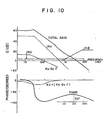
- Figs. 8 and 10 are Bode diagrams. It will be seen that the proportional sensitivity Kd of the push-pull loop is about 2 dB and is constant in the range of from dc to 10 KHz. The proportional sensitivity Kw of the wobbled loop is about 14 dB and is low-passed at 30 Hz. As will be apparent from the equation described above, (Kw - Kd) represents the amount of suppression for all the offsets including the gain offset occurring in the push-pull loop and is 12 dB and 9 dB at dc and 30 Hz respectively. Therefore, even when a dc offset of, for example, 0.1 J.1.m occurs, the practical track error is suppressed to 0.02 wm.
- the band of the wobbled loop is restricted by the period of the wobbled track marks, hence, by the sampling period. Therefore, in order to stabilize the operation of the servo system, it is necessary to attenuate the gain in the high-frequency range by the low-pass filter (Fw) 28.
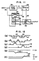
- Fig. 11 is a block diagram showing the basic structure of the tracking error detecting element 26 and sample-hold circuit 27 shown in Fig. 9.
- Fig. 12 shows signal waveforms appearing at various parts of Fig. 11. Waveforms shown in (a), (b), (c), (d) and (e) of Fig. 12 correspond to signals 40, 41, 42, 43 and 44 shown in Fig. 11 respectively.
- the relative luminance signal from the light detector 13 (the sum signal of the output signals of the light receiving sections 131 and 132) is applied as an input signal 40 having a waveform as shown in (a) of Fig. 12.
- This input signal 40 is applied to a binary coding circuit 35 where the input signal 40 is clipped at a threshold level 47 shown in (a) of Fig. 12 to be turned into a binary signal 41 having a waveform as shown in (b) of Fig. 12.
- the binary signal 41 is applied to a pit detecting circuit 36 where elongate pits (wobbled track marks) carrying track error information are detected.
- the pit detecting circuit 36 applies a first sample signal 42 having a waveform as shown in (c) of Fig. 12 to a first sample and hold circuit 37 and applies also a second sample signal 43 having a waveform as shown in (d) of Fig. 12 to a second sample and hold circuit 38.
- the information (22 shown in (a) of Fig. 12) contained in first elongate pit 20-1 is sampled by the sample and hold circuit 37 while the first sample signal 42 is in its high level, and is then held in the sample and hold circuit 37 as soon as the sample signal 42 is turned into its low level from the high level.
- an output signal 44 held at a level 22-1 and having a waveform as shown in (e) of Fig. 12 appears from the first sample and hold circuit 37.
- This output signal 44 from the sample and hold circuit 37 and the input signal 40 are applied to a differential circuit 39, and the output signal 24 of the differential circuit 39 is applied.to the second sample and hold circuit 38.
- the signal 24 is sampled while the second sample signal 43 is in its high level and is then held as soon as the signal 43 is turned into its low level from the high level.
- a tracking error signal 45 having a waveform as shown in (f) of Fig. 12 appears from the second sample and hold circuit 38.
- FIG. 13 is an enlarged view of part of the recordable/reproducible optical disc 10 employed in the present invention and illustrates that one of prewobbling elongated pits is damaged by a scar.
- a first prewobbling elongate pit 20-1 there are shown a first prewobbling elongate pit 20-1, a second prewobbling elongate pit 20-2, a pregroove 15 and a damaged portion 50.
- Fig. 13 is an enlarged view of part of the recordable/reproducible optical disc 10 employed in the present invention and illustrates that one of prewobbling elongated pits is damaged by a scar.
- a first prewobbling elongate pit 20-1 there are shown a first prewobbling elongate pit 20-1, a second prewobbling elongate pit 20-2, a pregroove 15 and a damaged portion 50.
- Fig. 13 there are shown a first prewobbling
- the length of 101 of the first elongate pit 20-1, the length 102 of the gap and length 103 of the second elongate pit 20-2 have a ratio of 6:4:6.
- the ratio is in no way limited to that specified above, when this part is regarded to be a servo mark (a wobbled track mark) and the pattern of modulation of an index and data to be recorded on the pregroove 15 is, for example, a two-to- seven modulation pattern.
- Fig. 14 is a block diagram showing the practical structure of the tracking error detecting circuit 26 utilizing the prewobbling pits.
- This tracking error detecting circuit 26 is provided by adding a servo mark detecting circuit 47 and a third sample and hold circuit 46 to the basic circuit block diagram shown in Fig. 11.
- Fig. 15 is a time chart of the operation of the circuit 26 shown in Fig. 14. In (a) of Fig. 15, there are shown an N-th servo mark period 51, an N-th pregroove period 52, and (N+1)-th servo mark period 51', and a damaged-portion period 53 due to the presence of a scar.
- Waveforme shown in (a), (b), (c), (d), (e), (f), (g) and (h) of Fig. 15 correspond to signals 40, 42, 43, 49, 44, 48, 24 and 45 shown in Fig. 14 respectively.
- the operation of the circuit 26 shown in Fig. 14 will be described with reference to Fig. 15 and part of Fig. 11.
- the relative luminance signal from the light detector 13 is applied as an input signal 40 having a waveform as shown in (a) of Fig. 15.
- This input signal 40 is applied to the binary coding circuit 35 where the input signal 40 is turned into a binary signal 41.
- the binary signal 41 is applied to the pit detecting circuit 36, and a signal 42 including a first sample pulse (s-own in (b) of Fig. 15) indicative of detection of the first elongate pit and a signal 43 including a second sample pulse (shown in (c) of Fig. 15) indicative of detection of the second elongate pit appear from the pit detecting circuit 36.
- the first and third sample and hold circuits 37 and 46 sample and hold the input signal 40.
- the output signal 44 of the first sample and hold circuit 37 having a waveform as shown in (e) of Fig. 15 and the output signal 48 of the third sample and hold circuit 46 having a waveform as shown in (f) of Fig. 15 are applied to the differential circuit 39, and a tracking error signal 24 having a waveform as shown in (g) of Fig. 15 appears from the differential circuit 39.
- the binary signal 41 is also applied to the servo mark detecting circuit 47 which carries out pattern matching and generates a mark detection signal 49 having a waveform as shown (d) of Fig. 15 when the servo mark is recognized as a result of pattern matching.
- the second or output sample and hold circuit 38 samples the tracking error detection signal 24 (H in (d) of Fig.
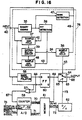
- Fig. 16 is a block diagram of another form of the tracking error detecting circuit 26 utilizing the prewobbling pits for tracking error detection according to the present invention.
- the first form of the tracking error detecting circuit described above includes still the possibility of unstable tracking when a plurality of damaged servo marks are present in the same track.
- the form shown in Fig. 16 can deal with the presence of plurality of damaged servo marks.
- Parts enclosed by the dotted line 76 have the same structure and operate in the some way as the equivalent parts of the circuit shown in Fig. 14, and such parts will not be especially referred to in the following description.
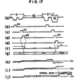
- Fig. 17 shows signal waveforms appearing at various parts of Fig. 16, and waveforms shown in (a), (b), (c), (d), (e), (f), (g), (h), (i) and (j) of Fig. 17 correspond to signals 40, 42, 43, 49, 66, 69, 70, 24, 72 and 68 shown in Fig. 16 respectively.
- the tracking error detecting circuit part 76 enclosed by the dotted line is unnecessary.
- the tracking error signal 16 detected from the pregrooves is apparently offset by the prewob- bllng tracking error signal 24 and is featured by the provision of a circuit, which stores the pregroove tracking error signal 16 when the servo marks are normally detected, but replaces the pregroove tracking error signal by the stored prewobbling tracking error signal when the servo marks are dropped out.
- a circuit is added to the track error detecting circuit part 76 shown in Fig. 14.
- a mark interpolating circuit 56 operates to apply a mark drop-out detection signal 66 as shown in (e) of Fig. 17 to the flip-flop 60 to set the flip-flop 60 as shown in (f) of Fig. 17.
- the analog switch 63 conducts now at its normally-open contact 65, and, at the same time, the data 72 of the inverted push-pull signal written in the memory 61 during normal operation is now read out from the memory 61.
- An output signal 73 as shown in (i) of Fig.
- a counter 58 is reset by a rotation synchronous signal 74 generated every complete rotation of the optical disc 10.
- the counter 58 is incremented by a leading edge of an output signal 67 of an OR circuit 57 to which the mark detection signal 49 and the mark drop-out detection signal 66 are applied.
- the resultant output signal 70 (shown in (g) of Fig. 17) of the counter 58 provides read/write address information applied to the memory 61.
- the embodiments of the tracking servo system of the present invention shown in Figs. 7 and 9 ensure tracking with high accuracy without giving rise to an undesinable offset.
- the present invention can stimulate a great process when applied to the field of digital discs, digital audio discs and the like.
- the present invention can obviate the defect of the prior art manner of information recording on pregrooves, that is, the defect of giving rise to a great tracking offset attributable to, for example, tilting of an optical disc.
- the present invention can also prevent mal-operation due to defective servo marks or sector marks on an optical disc, thereby eliminating the necessity for re-writing servo marks and/or sector marks and the necessity for replacement of the optical disc. Therefore, the present invention can improve the productivity of optical discs and can also reduce the manufacturing costs of optical discs.
Landscapes
- Optical Recording Or Reproduction (AREA)
Claims (18)
caractérisée en ce que le gain (Kw) dudit deuxième signal d'erreur de suivi dans une bande de fréquence basses est sélectionné de façon à être plus large que le gain (Kd) dudit premier signal d'erreur de suivi, et les composants de haute fréquence dudit deuxième signal d'erreur de suivi étant éliminés par un filtre (28) passe-bas à bande limitée qui a une fréquence critique plus petite que la fréquence d'échantillonnage.
caractérisé en ce que lesdits moyens de correction incluent un filtre (28) passe-bas pour limiter la bande dudit deuxième signal d'erreur de suivi et des moyens d'addeur (32) pour additionner un signal de sortie (31) dudit filtre passe-bas dudit premier signal d'erreur de suivi, ledit filtre passe-bas ayant une fréquence critique plus petite que la fréquence d'échantillonnage; et des moyens (30) pour actionner des moyens de contrôle de suivi disposés dans lesdits moyens d'irradiation en réponse à l'application d'un signal de sortie auxdits moyens de correction; lesdits deuxièmes moyens de détection (26) ayant une sensiblité de détection (Kw) dans une rangée de fréquence basse qui est plus grande que la sensibilité de détection (Kd) desdits premiers moyens de détection.
Applications Claiming Priority (6)
| Application Number | Priority Date | Filing Date | Title |
|---|---|---|---|
| JP63587/85 | 1985-03-29 | ||
| JP60063587A JPH0831213B2 (ja) | 1985-03-29 | 1985-03-29 | 光学的トラッキング方法 |
| JP146507/85 | 1985-07-05 | ||
| JP14650785A JPS628341A (ja) | 1985-07-05 | 1985-07-05 | 光学的情報記憶再生装置 |
| JP165777/85 | 1985-07-29 | ||
| JP60165777A JPH0746430B2 (ja) | 1985-07-29 | 1985-07-29 | 光学的情報記録再生方法 |
Publications (3)
| Publication Number | Publication Date |
|---|---|
| EP0210330A2 EP0210330A2 (fr) | 1987-02-04 |
| EP0210330A3 EP0210330A3 (en) | 1988-01-20 |
| EP0210330B1 true EP0210330B1 (fr) | 1990-10-24 |
Family
ID=27298219
Family Applications (1)
| Application Number | Title | Priority Date | Filing Date |
|---|---|---|---|
| EP86104340A Expired EP0210330B1 (fr) | 1985-03-29 | 1986-03-29 | Procédé et appareil pour un système d'asservissement de piste suivant la wobulation composée |
Country Status (3)
| Country | Link |
|---|---|
| US (1) | US4748609A (fr) |
| EP (1) | EP0210330B1 (fr) |
| DE (1) | DE3675096D1 (fr) |
Cited By (1)
| Publication number | Priority date | Publication date | Assignee | Title |
|---|---|---|---|---|
| US7110334B2 (en) | 1998-08-29 | 2006-09-19 | Samsung Electronics Co., Ltd. | Method for detecting servo error, apparatus therefor, disk which maintains quality of servo error signal, method of controlling servo of disk recording/reproducing apparatus, method of detecting tracking error, and method of detecting tilt error |
Families Citing this family (82)
| Publication number | Priority date | Publication date | Assignee | Title |
|---|---|---|---|---|
| JPH06103539B2 (ja) * | 1985-12-06 | 1994-12-14 | 株式会社日立製作所 | 光デイスクトラツキング装置 |
| DE3672426D1 (de) * | 1985-09-27 | 1990-08-09 | Sharp Kk | Spurnachlaufverfahren fuer eine optische speicherplatte. |
| JPS62109236A (ja) * | 1985-11-07 | 1987-05-20 | Teac Co | トラツキングサ−ボ装置 |
| US4866688A (en) * | 1985-12-20 | 1989-09-12 | Hitachi, Ltd. | Composite tracking servo system for optical disc apparatus with track offset correction |
| JPS62180568A (ja) * | 1986-02-04 | 1987-08-07 | Sony Corp | デイスク状記録媒体の欠陥検出装置 |
| JPS62229576A (ja) * | 1986-03-31 | 1987-10-08 | Canon Inc | 情報記録媒体のプリフオ−マツト形式 |
| JP2559372B2 (ja) * | 1986-07-09 | 1996-12-04 | 株式会社日立製作所 | 光ディスク装置及び光情報記録方法 |
| JP2796285B2 (ja) * | 1986-07-11 | 1998-09-10 | 株式会社日立製作所 | トラッキング方法及びそれを用いた光ディスク装置 |
| JPH0782656B2 (ja) * | 1986-07-11 | 1995-09-06 | 株式会社日立製作所 | 光デイスク装置 |
| US5144552A (en) * | 1986-07-25 | 1992-09-01 | Ricoh Company, Ltd. | Optical information storage medium having grooves and pits with specific depths, respectively |
| US4864552A (en) * | 1986-08-29 | 1989-09-05 | Laser Magnetic Storage International Company | Driving signal for coarse servo employing sampled offset signal |
| US4972402A (en) * | 1986-11-20 | 1990-11-20 | Canon Kabushiki Kaisha | Optical card |
| JPS63142533A (ja) * | 1986-12-03 | 1988-06-14 | Fujitsu Ltd | 光学的記録再生装置 |
| JPH0679378B2 (ja) * | 1986-12-15 | 1994-10-05 | ソニー株式会社 | 光学式記録再生装置のトラツキングサ−ボ回路 |
| US5136568A (en) * | 1986-12-15 | 1992-08-04 | Deutsche Thomson-Brandt Gmbh | Tracking circuit for guiding a beam of light along data tracks of a recorded medium |
| JP2550051B2 (ja) * | 1987-02-25 | 1996-10-30 | 株式会社日立製作所 | 光カード,光カードの記録再生方法,及び,光カード記録再生装置 |
| JPH0731813B2 (ja) * | 1987-02-27 | 1995-04-10 | 株式会社日立製作所 | 光デイスク |
| US5214635A (en) * | 1987-02-27 | 1993-05-25 | Matsushita Electric Industrial Co., Ltd. | Erasable optical disk and optical information recording/reproduction apparatus |
| KR910008503B1 (ko) * | 1987-03-13 | 1991-10-18 | 미쯔비시덴끼 가부시끼가이샤 | 광 디스크 |
| US4860271A (en) * | 1987-03-13 | 1989-08-22 | Pioneer Electronic Corporation | Servo circuit for generating a tracking error signal for optical disk player |
| JP2619381B2 (ja) * | 1987-03-20 | 1997-06-11 | 株式会社日立製作所 | 光学的情報再生装置 |
| JP2548186B2 (ja) * | 1987-04-13 | 1996-10-30 | パイオニア株式会社 | 案内溝付光デイスク |
| JPH0719385B2 (ja) * | 1987-04-24 | 1995-03-06 | 株式会社日立製作所 | 光学的記録再生装置 |
| JPH07118166B2 (ja) * | 1987-05-21 | 1995-12-18 | パイオニア株式会社 | トラッキング回路 |
| JPS63306535A (ja) * | 1987-06-05 | 1988-12-14 | Sharp Corp | 光学的記録再生装置 |
| US4779251A (en) * | 1987-06-12 | 1988-10-18 | Optimem | Optical disk memory system with closed loop micro-jump between adjacent tracks |
| US5166921A (en) * | 1987-06-17 | 1992-11-24 | Pioneer Electronic Corporation | Optical disk carrying tracking information in multiple formats and apparatus for analyzing same |
| JP2585281B2 (ja) * | 1987-08-19 | 1997-02-26 | 株式会社日立製作所 | 光ディスク装置 |
| JP2911449B2 (ja) * | 1987-10-29 | 1999-06-23 | パイオニア株式会社 | 光学式情報読取装置 |
| JPH0721879B2 (ja) * | 1987-11-07 | 1995-03-08 | 株式会社日立製作所 | 光ディスク用レプリカ基盤,スタンパまたは原盤 |
| EP0317344B1 (fr) * | 1987-11-18 | 1994-06-08 | Sharp Kabushiki Kaisha | Matériau pour mémoire optique |
| JP2735220B2 (ja) * | 1987-12-02 | 1998-04-02 | 株式会社日立製作所 | 非点収差を有する光束を用いた焦点ずれ検出方法及び光ディスク装置 |
| EP0320975B1 (fr) * | 1987-12-18 | 1994-11-30 | Hitachi, Ltd. | Méthode et appareil d'enregistrement et de reproduction d'informations |
| NL8800152A (nl) * | 1988-01-22 | 1989-08-16 | Philips Nv | Optische uitleesbare registratiedrager van het beschrijfbare type, een inrichting voor het vervaardigen van een dergelijke registratiedrager, en inrichtingen voor het optekenen en/of uitlezen van informatie op/uit een dergelijke registratiedrager. |
| DE68910990T2 (de) * | 1988-01-22 | 1994-06-01 | Philips Nv | Verfahren und Gerät zur aufeinanderfolgenden Aufzeichnung von EFM-modulierten Signalen. |
| NL8800151A (nl) * | 1988-01-22 | 1989-08-16 | Philips Nv | Werkwijze en inrichting voor het optekenen van een informatiesignaal. |
| JP2669532B2 (ja) * | 1988-05-20 | 1997-10-29 | 株式会社日立製作所 | 光ディスク装置 |
| US4969750A (en) * | 1988-10-14 | 1990-11-13 | Rousseau Research Inc. | Method of shipment and containment of hazardous liquids |
| JPH02130727A (ja) * | 1988-11-10 | 1990-05-18 | Sony Corp | ディスク状記録媒体 |
| JP2764960B2 (ja) * | 1988-11-16 | 1998-06-11 | 松下電器産業株式会社 | 記録再生方法 |
| JPH03219434A (ja) * | 1988-12-27 | 1991-09-26 | Canon Inc | 光学的情報記録媒体 |
| US5218589A (en) * | 1989-04-24 | 1993-06-08 | Ricoh Company, Ltd. | Defect detecting method |
| ES2080938T3 (es) * | 1989-12-04 | 1996-02-16 | Thomson Brandt Gmbh | Un sistema de seguimiento en un dispositivo optico de registro/reproduccion. |
| JP2813042B2 (ja) * | 1990-07-04 | 1998-10-22 | 株式会社リコー | 光ピックアップ装置の欠陥検出回路 |
| US5305159A (en) * | 1990-08-08 | 1994-04-19 | Kabushiki Kaisha Toshiba | Magnetic disk apparatus |
| FR2676565B1 (fr) * | 1991-05-14 | 1996-04-12 | Art Gigadisc Atg | Support d'informations lisibles optiquement et appareil de lecture d'un tel support. |
| JPH05128594A (ja) * | 1991-10-31 | 1993-05-25 | Sony Corp | 変位量測定方法 |
| US5508995A (en) * | 1993-07-15 | 1996-04-16 | Matsushita Electric Industrial Co., Ltd. | Optical disk capable of recording information on both groove and land tracks |
| JP3300138B2 (ja) * | 1993-11-19 | 2002-07-08 | パイオニア株式会社 | 光ディスク |
| US5440534A (en) * | 1994-01-10 | 1995-08-08 | Eastman Kodak Company | Method and apparatus for maintaining a recording light beam in an on-track position on a recording medium |
| US5561655A (en) * | 1994-12-02 | 1996-10-01 | Eastman Kodak Company | Apparatus and method for differential tracking in a magneto-optic data storage system using mark edge detection |
| JP3269309B2 (ja) * | 1995-01-24 | 2002-03-25 | 松下電器産業株式会社 | 光ディスクの制御装置 |
| TW363182B (en) * | 1995-02-09 | 1999-07-01 | Hitachi Ltd | Positioning apparatus for optical disks |
| US7092349B2 (en) * | 1995-02-14 | 2006-08-15 | Hitachi, Ltd. | Optical reproducing method optical medium with aligned prepit portion |
| US5982738A (en) | 1995-02-14 | 1999-11-09 | Hitachi, Ltd. | Optical recording medium having at least wobbled synchronous information shared between tracks |
| JPH08329492A (ja) * | 1995-05-30 | 1996-12-13 | Nippon Conlux Co Ltd | 光学的記録媒体に対するトラッキング方法および装置 |
| US6118752A (en) * | 1995-07-07 | 2000-09-12 | Matsushita Electric Industrial Co., Ltd. | Optical information recording medium offset pre-pit array indicating identification information |
| US5787228A (en) | 1996-02-28 | 1998-07-28 | Fiely; Sharon K. | Portable vehicle articulated windshield defroster with heated air-flow and timer |
| US6744706B2 (en) | 1995-07-07 | 2004-06-01 | Matsushita Electric Industrial Co. | Optical system with tracking controller |
| JP3103505B2 (ja) * | 1996-06-26 | 2000-10-30 | 三菱電機株式会社 | 光ディスク及び光ディスク駆動装置 |
| TW357345B (en) * | 1996-06-26 | 1999-05-01 | Matsushita Electric Industrial Co Ltd | CD having re-write area and ROM area |
| JP3418065B2 (ja) * | 1996-06-26 | 2003-06-16 | 三菱電機株式会社 | 光ディスク |
| KR100271569B1 (ko) * | 1997-08-25 | 2000-11-15 | 구자홍 | 편심억압서보방법및이를이용한서보장치 |
| JP3882303B2 (ja) | 1997-12-26 | 2007-02-14 | ソニー株式会社 | 光ディスクの記録及び/又は再生装置並びに光ディスクのトラッキング制御方法 |
| EP1040471A1 (fr) * | 1998-08-04 | 2000-10-04 | Koninklijke Philips Electronics N.V. | Disque optique et dispositif de balayage du disque |
| EP0987691B1 (fr) * | 1998-09-14 | 2000-10-04 | Matsushita Electric Industrial Co., Ltd. | Dispositif pour détecter une inclinaison, dispositif d'enregistrement et de reproduction de disque optique, et procédé de détection d'inclinaison |
| KR100565043B1 (ko) * | 1998-09-15 | 2006-03-30 | 삼성전자주식회사 | 틸트 및 디트랙 검출 장치, 틸트 및 디트랙 제어 장치, 이에 적합한 기준값 설정 방법 그리고 이에 적합한 디스크 |
| JP3486145B2 (ja) | 2000-01-17 | 2004-01-13 | 松下電器産業株式会社 | デジタル記録データ再生装置 |
| CN100336120C (zh) * | 2000-06-26 | 2007-09-05 | 松下电器产业株式会社 | 光学头 |
| EP1310951B1 (fr) * | 2000-06-26 | 2008-10-01 | Matsushita Electric Industrial Co., Ltd. | Tete optique |
| JP3665588B2 (ja) * | 2001-04-20 | 2005-06-29 | 株式会社東芝 | ディスク、ディスク装置及びトラックセンター検出方法 |
| CN1625689A (zh) | 2002-01-31 | 2005-06-08 | 长冈实业株式会社 | 通过盘槽以及相关光分析盘触发的方法和系统 |
| JP2005524192A (ja) | 2002-05-01 | 2005-08-11 | エルジー エレクトロニクス インコーポレーテッド | 高密度再生専用光ディスクとそれによる光ディスク装置及び方法 |
| MXPA04001985A (es) * | 2002-07-02 | 2005-02-17 | Lg Electronics Inc | Disco optico de alta densidad y metodo para restringir la reproduccion del disco optico de alta densidad en un aparato de disco optico. |
| WO2004105000A1 (fr) * | 2003-05-20 | 2004-12-02 | Samsung Electronics Co., Ltd. | Support de mise en memoire de l'information et procede et appareil d'enregistrement et/ou de reproduction de donnees sur et/ou a partir dudit support |
| KR100750111B1 (ko) * | 2003-05-20 | 2007-08-17 | 삼성전자주식회사 | 정보 저장매체 및 데이터의 기록 및/또는 재생 장치 |
| JP4099104B2 (ja) * | 2003-05-23 | 2008-06-11 | パイオニア株式会社 | 情報記録再生装置 |
| US8023392B2 (en) * | 2006-12-15 | 2011-09-20 | Seagate Technology Llc | Compensating the effects of non-synchronous writing of erasable servo marks |
| US20090086360A1 (en) * | 2007-10-02 | 2009-04-02 | Seagate Technology Llc | Low Complexity Servo Demodulation Algorithm for Probe Storage |
| JP2009205765A (ja) * | 2008-02-28 | 2009-09-10 | Toshiba Corp | 光ディスク装置およびトラッキング制御方法 |
| US8897108B1 (en) * | 2012-04-26 | 2014-11-25 | Marvell International Ltd. | Single beam radial tracking method for optical discs |
| EP3827415A1 (fr) * | 2018-07-26 | 2021-06-02 | NVIDIA Corporation | Éclairage global utilisant des contributions d'éclairage partagées pour des interactions dans le suivi de trajet |
Family Cites Families (18)
| Publication number | Priority date | Publication date | Assignee | Title |
|---|---|---|---|---|
| NL160138C (nl) * | 1972-05-11 | 1979-09-17 | Philips Nv | Inrichting voor het uitlezen van een vlakke registratie- drager. |
| JPS5415727B2 (fr) | 1973-02-02 | 1979-06-16 | ||
| NL187413C (nl) * | 1978-03-16 | 1991-09-16 | Philips Nv | Registratiedragerlichaam, ingeschreven registratiedrager, werkwijze voor het inschrijven van het registratiedragerlichaam en inrichting voor het uitvoeren van de werkwijze en voor het uitlezen van een ingeschreven registratiedrager. |
| NL7810462A (nl) * | 1978-10-19 | 1980-04-22 | Philips Nv | Registratiedrager waarin informatie is aangebracht in een optisch uitleesbare stralingsreflekterende informatiestruktuur |
| US4364118A (en) * | 1979-06-25 | 1982-12-14 | Hitachi, Ltd. | Optical disk and optical information processor |
| NL8000122A (nl) * | 1980-01-09 | 1981-08-03 | Philips Nv | Schijfvormige, optisch uitleesbare registratiedrager als opslagmedium voor datainformatie, inrichting voor het vervaardigen van zo'n registratiedrager, inrichting voor het optekenen en/of weergeven van datainformatie in c.q. van zo'n registratiedrager. |
| NL8006165A (nl) * | 1980-11-12 | 1982-06-01 | Philips Nv | Systeem voor het overdragen van digitale informatie, codeerinrichting voor toepassing in dat systeem, decodeerinrichting voor toepassing in dat systeem en registratiedrager voor toepassing in dat systeem. |
| JPS5856236A (ja) | 1981-09-28 | 1983-04-02 | Hitachi Ltd | 光学的トラック位置検出装置およびそれを用いた光学的記録再生装置 |
| US4402061A (en) * | 1981-10-15 | 1983-08-30 | Burroughs Corporation | Preformatted optical media for use in an optical memory system |
| US4443870A (en) * | 1981-10-15 | 1984-04-17 | Burroughs Corporation | Optical memory system providing track following |
| US4428069A (en) * | 1981-12-21 | 1984-01-24 | Burroughs Corporation | Apparatus for preformatting an optical disk |
| US4432083A (en) * | 1982-02-17 | 1984-02-14 | Burroughs Corporation | Optical memory system having track following |
| FR2523349A1 (fr) * | 1982-03-12 | 1983-09-16 | Thomson Csf | Procede et dispositif optique de generation de signaux d'asservissements de la position d'une tache d'exploration des pistes d'un support d'information |
| FR2523347B1 (fr) * | 1982-03-12 | 1988-11-04 | Thomson Csf | Support d'information mobile pregrave et dispositif optique de suivi de piste mettant en oeuvre un tel support |
| US4456981A (en) * | 1982-03-19 | 1984-06-26 | Magnetic Peripherals Inc. | Modulation system for optical recording |
| JPS5919250A (ja) * | 1982-07-21 | 1984-01-31 | Hitachi Ltd | 情報の記録再生装置 |
| JPH0680535B2 (ja) * | 1982-08-27 | 1994-10-12 | 株式会社日立製作所 | 情報の記録再生方法 |
| NL8300291A (nl) * | 1983-01-27 | 1984-08-16 | Philips Nv | Inrichting voor het uitlezen van een optische registratiedrager. |
-
1986
- 1986-03-28 US US06/845,340 patent/US4748609A/en not_active Expired - Lifetime
- 1986-03-29 EP EP86104340A patent/EP0210330B1/fr not_active Expired
- 1986-03-29 DE DE8686104340T patent/DE3675096D1/de not_active Expired - Lifetime
Cited By (5)
| Publication number | Priority date | Publication date | Assignee | Title |
|---|---|---|---|---|
| US7110334B2 (en) | 1998-08-29 | 2006-09-19 | Samsung Electronics Co., Ltd. | Method for detecting servo error, apparatus therefor, disk which maintains quality of servo error signal, method of controlling servo of disk recording/reproducing apparatus, method of detecting tracking error, and method of detecting tilt error |
| US7167424B2 (en) | 1998-08-29 | 2007-01-23 | Samsung Electronics Co., Ltd. | Method for detecting servo error, apparatus therefor, disk which maintains quality of servo error signal, method of controlling servo of disk recording/reproducing apparatus, method of detecting tracking error, and method of detecting tilt error |
| SG134979A1 (en) * | 1998-08-29 | 2007-09-28 | Samsung Electronics Co Ltd | Method for detecting servo errors from a disk |
| US7319643B2 (en) | 1998-08-29 | 2008-01-15 | Samsung Electronics Co., Ltd. | Method for detecting servo error, apparatus therefor, disk which maintains quality of servo error signal, method of controlling servo of disk recording/reproducing apparatus, method of detecting tracking error, and method of detecting tilt error |
| US7590034B2 (en) | 1998-08-29 | 2009-09-15 | Samsung Electronics Co., Ltd. | Method for detecting servo error, apparatus therefor, disk which maintains quality of servo error signal, method of controlling servo of disk recording/reproducing apparatus, method of detecting tracking error, and method of detecting tilt error |
Also Published As
| Publication number | Publication date |
|---|---|
| US4748609A (en) | 1988-05-31 |
| DE3675096D1 (de) | 1990-11-29 |
| EP0210330A3 (en) | 1988-01-20 |
| EP0210330A2 (fr) | 1987-02-04 |
Similar Documents
| Publication | Publication Date | Title |
|---|---|---|
| US4748609A (en) | Method and apparatus for composite tracking servo system with track offset correction and rotary optical disc having at least one correction mark for correcting track offset | |
| US4707816A (en) | Method and apparatus for composite wobbled and push-pull tracking servo system | |
| US5084860A (en) | Apparatus for optical disc memory with correction pattern and master disc cutting apparatus | |
| EP0727779B1 (fr) | Procédé d'enregistrement optique utilisant l'enregistrement sur sillon et parties plates intermédiaires, et milieu d'enregistrement optique pour ce procédé | |
| EP0077643B1 (fr) | Système de mémoire optique à commande de focalisation améliorée | |
| JPH0690804B2 (ja) | 光学的情報記録再生装置 | |
| JP2775956B2 (ja) | 記録媒体 | |
| US5034934A (en) | Opto-magnetic disk unit with improved dynamic range characteristics and opto-magnetic disk therefor | |
| JPH0746430B2 (ja) | 光学的情報記録再生方法 | |
| US6744706B2 (en) | Optical system with tracking controller | |
| JP2528822B2 (ja) | 情報記録媒体およびその記録再生装置 | |
| EP0457536B1 (fr) | Milieu d'enregistrement optique et appareil d'enregistrement optique | |
| JPH024062B2 (fr) | ||
| JPS61224145A (ja) | 光学的トラッキング方法 | |
| EP0474214B1 (fr) | Appareil pour reproduire des données d'adresse sur un disque | |
| JP2954037B2 (ja) | 円盤状記録媒体 | |
| JP3231506B2 (ja) | 情報記録方法及び情報再生方法 | |
| JP3086465B2 (ja) | 信号再生方法 | |
| JP3401459B2 (ja) | チルト検出装置および光ディスク装置、チルト制御方法 | |
| JP3401460B2 (ja) | チルト検出装置および光ディスク装置、チルト制御方法 | |
| JP3132692B2 (ja) | 光デイスク装置 | |
| JP3101410B2 (ja) | 光ディスクプレーヤ | |
| EP0555037B1 (fr) | Appareil d'enregistrement/reproduction d'information magnétooptique | |
| JPS6344327A (ja) | 光学的情報記録再生装置のトラツキング装置 | |
| JPH06168451A (ja) | 光ディスク装置 |
Legal Events
| Date | Code | Title | Description |
|---|---|---|---|
| PUAI | Public reference made under article 153(3) epc to a published international application that has entered the european phase |
Free format text: ORIGINAL CODE: 0009012 |
|
| 17P | Request for examination filed |
Effective date: 19860414 |
|
| AK | Designated contracting states |
Kind code of ref document: A2 Designated state(s): DE GB |
|
| PUAL | Search report despatched |
Free format text: ORIGINAL CODE: 0009013 |
|
| AK | Designated contracting states |
Kind code of ref document: A3 Designated state(s): DE GB |
|
| 17Q | First examination report despatched |
Effective date: 19880718 |
|
| GRAA | (expected) grant |
Free format text: ORIGINAL CODE: 0009210 |
|
| AK | Designated contracting states |
Kind code of ref document: B1 Designated state(s): DE GB |
|
| REF | Corresponds to: |
Ref document number: 3675096 Country of ref document: DE Date of ref document: 19901129 |
|
| PLBE | No opposition filed within time limit |
Free format text: ORIGINAL CODE: 0009261 |
|
| STAA | Information on the status of an ep patent application or granted ep patent |
Free format text: STATUS: NO OPPOSITION FILED WITHIN TIME LIMIT |
|
| 26N | No opposition filed | ||
| REG | Reference to a national code |
Ref country code: GB Ref legal event code: IF02 |
|
| PGFP | Annual fee paid to national office [announced via postgrant information from national office to epo] |
Ref country code: GB Payment date: 20050228 Year of fee payment: 20 |
|
| PGFP | Annual fee paid to national office [announced via postgrant information from national office to epo] |
Ref country code: DE Payment date: 20050304 Year of fee payment: 20 |
|
| PG25 | Lapsed in a contracting state [announced via postgrant information from national office to epo] |
Ref country code: GB Free format text: LAPSE BECAUSE OF EXPIRATION OF PROTECTION Effective date: 20060328 |
|
| REG | Reference to a national code |
Ref country code: GB Ref legal event code: PE20 |