EP0210805A2 - Cathode pour tube électronique - Google Patents
Cathode pour tube électronique Download PDFInfo
- Publication number
- EP0210805A2 EP0210805A2 EP86305560A EP86305560A EP0210805A2 EP 0210805 A2 EP0210805 A2 EP 0210805A2 EP 86305560 A EP86305560 A EP 86305560A EP 86305560 A EP86305560 A EP 86305560A EP 0210805 A2 EP0210805 A2 EP 0210805A2
- Authority
- EP
- European Patent Office
- Prior art keywords
- earth metal
- layer
- cathode
- electron
- metal oxide
- Prior art date
- Legal status (The legal status is an assumption and is not a legal conclusion. Google has not performed a legal analysis and makes no representation as to the accuracy of the status listed.)
- Granted
Links
Images


Classifications
-
- H—ELECTRICITY
- H01—ELECTRIC ELEMENTS
- H01J—ELECTRIC DISCHARGE TUBES OR DISCHARGE LAMPS
- H01J1/00—Details of electrodes, of magnetic control means, of screens, or of the mounting or spacing thereof, common to two or more basic types of discharge tubes or lamps
- H01J1/02—Main electrodes
- H01J1/13—Solid thermionic cathodes
- H01J1/14—Solid thermionic cathodes characterised by the material
- H01J1/142—Solid thermionic cathodes characterised by the material with alkaline-earth metal oxides, or such oxides used in conjunction with reducing agents, as an emissive material
Definitions
- This invention relates to a cathode for an electron tube such as a cathode-ray tube of a TV set and particularly to an improvement in electron emission characteristics of the cathode.
- Fig. 1 is a schematic sectional view illustrating a structure of a cathode for use in a cathode-ray tube (CRT) or an image pickup tube for a TV system.
- a layer 2 of an electron-emissive substance made of an alkaline earth metal oxide containing at least Ba and further containing SrO and/or CaO is formed on a cylindrical base 1 made of Ni as a major element containing a small amount of a reducing element such as Si or Mg.
- a heater 3 is provided inside the base 1 and the electron-emissive layer 2 is heated by the heater 3 to emit thermal electrons.
- Such a conventional cathode is manufactured by a process as described below.
- a suspension of a carbonate of an alkaline earth metal (Ba, Sr, Ca, etc.) is sprayed on the base 1 and the applied suspension is heated by the heater 3 in a dynamic vacuum.
- the alkaline earth metal carbonate is converted to an oxide.
- the alkaline earth metal oxide is partially reduced at a high temperature of 900 to 1000°C so that it is activated to have a semiconductive property, whereby an electron-emissive layer 2 made of an alkaline earth metal oxide is formed on the base 1.
- a reducing element such as Si or Mg contained in the base 1 diffuses to move toward the interface between the alkaline earth metal oxide layer and the base 1, and then reacts with the alkaline earth metal oxide.
- the alkaline earth metal oxide is barium oxide (BaO)
- the reaction is expressed by the following formula (1) or (2).
- the alkaline earth metal oxide layer 2 formed on the base 1 is partially reduced to become a semiconductor of an oxygen vacancy type. Consequently, an emission current of 0.5 to 0.8 A/cm 2 is obtained under the normal condition at an operation temperature of 700 to 800°C.
- a current density higher than 0.5 to 0.8 A/cm 2 can not be obtained for the following reasons.
- an intermediate layer of an oxide or a composite oxide such as SiO 2 , MgO or Ba0 ⁇ SiO 2 is formed in the interface region between the base 1 and the alkaline earth metal layer 2 as is obvious from the formulas (1) and (2), so that the current is limited by a high resistance of the intermediate layer.
- the intermediate layer serves to prevent the reducing element in the base 1 from diffusing into the electron-emissive layer 2 so that a sufficient amount of Ba may not be generated.
- the thickness of the base 1 is made thin to obtain a rapid response rate in reaction in the cathode and for the purposes of preventing exhaustion of the reducing agent during the lifetime of the cathode and preventing lowering of the strength of the base 1, lanthanum is contained in a dispersed manner in the base 1 in the form of LaNi 5 and La 2 O 3.
- a cathode formed by pressing powder of mixture of W and Ba 3 Sc 4 O 9 is disclosed by A. van Oostrom et al. in Applications of Surface Science 2 (1979), pp. 173-186.
- German Patent Laying-Open Gazette No. 2626700 discloses an electron-emissive substance for high-pressure discharge lamp where an alkaline earth metal oxide such as BaO is mixed with an oxide of W or Mo and a rare earth metal oxide.
- a principal object of this invention is to provide an indirectly heated cathode in which electron emission characteristics have been improved.
- a cathode comprises: a base containing Ni as a major element; and a layer of an electron-emissive substance formed on the base, this layer containing not only an alkaline earth metal oxide as a principal component containing at least Ba but also a rare earth metal oxide of 0.1 to 20 wt.% or a rare earth metal of 0.05 to 15 wt.%.
- a cathode comprises: a base containing Ni as a major element; an intermediate layer of a rare earth metal oxide of 10 ⁇ m or less in thickness or a rare earth metal of 6 ⁇ m or less in thickness formed on the base; an electron-emissive layer of an alkaline earth metal oxide formed on the above stated intermediate layer and containing at least Ba.
- a cathode comprises: a base containing not only Ni as a major element but also a rare earth metal of 0.01 to 0.5 wt.%; and an electron-emissive layer of an alkaline earth metal oxide containing at least Ba.
- a layer 2 of an electron-emissive substance formed on a base 1 comprises an alkaline earth metal oxide as a principal component containing at least Ba and additionally containing Sr and/or Ca in certain circumstances.
- This layer 2 of the electron-emissive substance further contains a rare earth metal oxide of Sc or Y in 0.1 to 20 wt.%.
- the above described cathode can be manufactured by the below described process.
- scandium oxide powder or yttrium oxide powder is mixed in a ternary carbonate containing Ba, Sr and Ca, by an amount corresponding to a desired wt.% (to be obtained after the above stated ternary carbonate has been all converted to oxide).
- nitrocellulose lacquer and butyl acetate are added to the mixture thus obtained so that a suspension is prepared.
- This suspension is applied to the base 1 containing Ni as a major element by a spray method so that the applied suspension has a thickness of approximately 80 ⁇ m.
- the carbonate is decomposed to oxide, in the same manner as in the prior art, and the oxide is partially reduced so that the electron-emissive layer 2 on the base 1 is activated.
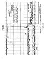
- cathodes provided with electron-emissive layers 2 containing SC203 or Y 2 0 3 in various wt.% were prepared. Then, diode vacuum tubes using those cathodes were prepared and they were subjected to life tests using various constant current densities so that changes in the emission current under the normal condition after the tests were examined. Fig.
- FIG. 2A shows the emission current in a cathode containing Sc 2 O 3 in 5 wt.%, a cathode containing Y 2 0 3 in 12 wt.% and a conventional cathode not containing any rare earth metal oxide, respectively, after the life test using a constant current density (2.05 A/cm 2 ) 3.1 times as large as the operation current density 0.66 A/cm 2 of a conventional cathode for C R T under the normal condition.
- the vertical axis in Fig. 2A represents the ratio of the emission current under the normal condition after the life test to the initial emission current under the normal condition.
- an initial emission current of 1 to 2 A/cm 2 ' can be obtained under the normal condition at the operation temperature of 700 to 800°C.
- the cathodes containing rare earth metal oxides have characteristics that the emission current after the life test with the high current density is less lowered as compared with the conventional cathode.
- Fig. 2B shows the ratio of the emission current under the normal condition after the life tests of 6000 hr to the initial emission current under the normal condition, as the result of the life tests conducted using a constant current density of 0.66 A/cm and constant current densities of twice, 3.1 times and 4 times that value with respect to the cathodes provided with electron-emissive layers 2 containing Sc 2 O 3 or Y 2 O 3 in various wt.%.
- Sc 2 O 3 or Y 2 O 3 more than 0 .1 wt.% has an effect in preventing lowering of the emission current under the normal condition after the life test with the high current density.
- the content of a rare earth metal oxide in the electron-emissive layer 2 is preferably in the range from 0.1 to 20 wt.% and more preferably in the range from 0.3 to 15 wt.%.
- Fig. 3A shows the results of the analysis in the interface region between the base 1 and the electron-emissive layer 2 of the conventional cathode.
- the reducing agents Si and Mg are segregated in the vicinity of the interface between the base 1 containing Ni as a major element and the electron-emissive layer 2.
- a peak of Si and that of Mg are observed at a position of approximately 5 ⁇ m from the interface toward the base 1 and at a position of approximately 3 to 5 ⁇ m from the interface toward the electron-emissive layer 2, respectively.
- the largest peak of Si is observed at a position of approximately 13 ⁇ m from the interface toward the electron-emissive layer 2.
- peaks of Ba were observed at the same positions as the peak positions of Mg and Si in the electron-emissive layer. Since these peak positions of Si, Mg and Ba are almost coincident to the peak positions of oxygen, these elements are considered to exist as oxides or composite oxides.
- layers of Si0 2 , MgO and a composite oxide thereof are formed in the grain boundary in the base 1 near the interface during the life test with the high current density and layers of oxides BaO, MgO and SiO 2 and composite oxides thereof are formed in the electron-emissive layer 2 at locations near the interface.
- the layer of SiO 2 ⁇ MgO and the layer of BaO ⁇ SiO 2 suppress diffusion of the reducing agents Si and Mg from the base 1 into the electron-emissive layer 2 and also suppress flow of electric current because of high resistance of those layers.
- Fig. 3B shows results of the analysis of the cathode containing SC203 according to this embodiment.
- the elements Si and Mg are dispersed uniformly in each of the base region and the electron-emissive region and such high peaks as shown in Fig. 3A are not observed.
- the rare earth metal oxide prevents oxidation of the interfacial layer of the base 1 when the alkaline earth metal carbonate is decomposed to oxide or when dissociation reaction occurs in BaO or the like during the operation of the cathode.
- the base 1 contains Si and Mg as reducing agents, layers of SiO 2 and MgO are formed in the vicinity of the interface if Sc 2 0 3 is not contained in the electron-emissive layer. Accordingly, diffusion of the reducing agents Si and Mg into the electron-emissive layer 2 is limited by the oxide layers of Sio 2 and MgO and the reactions represented by the formulas (1) and (2) occur only in the vicinity of those oxide layers. As a result, oxide layers of Si0 2 and MgO are formed preferentially in the vicinity of the interface particularly during the life test with the high current density and diffusion of Si and Mg into the electron-emissive layer is further limited, and thus the emission current under the normal condition is extremely lowered.
- the rare earth metal oxide in the electron-emissive layer 2 suppress oxidation of Ni, Si and Mg to prevent formation of an oxide film in the interface region and in consequence the reducing elements Si and Mg easily diffuse deep into the electron-emissive layer 2. Accordingly, the reactions represented by the formulas (1) and (2) occur more homogeneously within the electron-emissive layer 2.
- the rare earth metal oxide suitably controls diffusion rate of the reducing elements in the electron-emissive layer, the emission characteristics of the cathode can be maintained stably and in good condition even after the life test with the high current density for a long period.
- a cathode containing a rare earth metal oxide of less than 0.1 wt.% can hot achieve satisfactorily the effect of suppressing formation of the oxide layers of SiO 2 and MgO in the vicinity of the interface and as a result the emission characteristics can not be improved sufficiently.
- a rare earth metal oxide of more than 20 wt.% suppresses excessively diffusion of the reducing elements in the electron-emissive layer 2 and the emission characteristics can not be improved sufficiently either.
- rare earth metal oxides containing La, Ce, Pr, Nd, Sm, Gd, Dy, H o, E r, T m, etc. are used.
- Such oxides as Sc203, Y 2 0 3 and Ce 2 0 3 are particularly preferred.
- rare earth metal oxide powder is subjected to a heat treatment in a reducing atmosphere before it is mixed with an alkaline earth metal oxide.
- This heat treatment may be performed in a gas containing hydrogen at a temperature of 800°C or more, preferably 1000°C or more, for a period of 10 minutes or more.
- This heat treatment causes partial reduction of the rare earth metal oxide thereby to enhance the reactive property of the rare earth metal oxide.
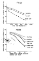
- Fig. 4A shows, in the same manner as in Fig. 2A, the emission current after the life test with 2.05 A/cm 2 with regard to cathodes according to this embodiment.
- the lowering of the emission current in Fig. 4A is suppressed a little further than that in Fig. 2A.
- Fig. 4B shows, in the same manner as in Fig. 2B, the emission current of cathodes according to this embodiment after the life tests of 6000 hr using various high current densities.
- the decrease of the emission current in Fig. 4B is suppressed a little more than that in Fig. 2B.
- a rare earth metal oxide is contained in the electron-emissive layer in the form of a composite oxide of Ba 3 Sc 4 0 9 or Ba 3 Y 4 O 9 .
- Fig. 5A shows, in the same manner as in Fig. 2A, the emission current after the life test with 2.05 A/cm 2 with regard to cathodes according to this embodiment.
- Fig. 5B shows, in the same manner as in Fig. 2B, the emission current after the life test with various high current densities with regard to cathodes according to this embodiment.
- the electron-emissive layer 2 contains not only a rare earth metal oxide of 0.1 to 20 wt.% but also powder of 10 wt.% or less comprising at least one of Ni and Co.
- Ni and/or Co powder serves to provide a better conductivity for the electron-emissive layer 2 and to improve the adhesive property of this layer 2 to the base.
- Table I indicates the emission current under the normal condition as to cathodes according to this embodiment after the life test of 6000 hr using a high current density (2.6 A/cm 2 ) 4 times as large as 0.66 A/cm 2 .
- sample 0 is a conventional cathode in which the electron-emissive layer comprises a ternary alkaline earth metal oxide of (Ba, Sr, Ca) 0.
- Samples 1 through 12 contain Sc 2 0 3 and Ni in addition to the ternary alkaline earth metal oxide.
- Sc 2 O 3 of 0.1 to 20 wt.% and Ni of less than 10 wt.% are preferred for improvement of the emission characteristics of the cathode.
- Ni exceeds 10 wt.%, sintering occurs between the Ni powder and the alkaline earth metal oxide powder to cause unfavorable influence on the surface of the electron-emissive layer, resulting in deterioration of the electron emission characteristics.
- an electron-emissive layer containing Co can also be used effectively.
- the electron-emissive layer 2 contains not only scandium oxide of 0.1 to 20 wt.% but also a reducing metal of 1 wt.% or less.
- Table II shows, in the same manner as Table I, the emission current after the life test with the high current density as to cathodes containing Fe as a reducing element.
- the reducing element Fe assists the rare earth metal oxide in suppressing formation of oxide layers of SiO 2 and MgO in the interfacial layer of the base 1.
- the content of Fe is preferably 1 wt.% or less. If it exceeds 1 wt.%, the alkaline earth metal oxide is reduced excessively and Ba is produced in an excessive amount, causing the lifetime of the cathode to be decreased.
- Fe was described as the reducing metal in this embodiment, such metals as Ti, Zr, Hf, V, Nb, Ta, Si A l, Cu, Z n, Cr, Mo and W may also be used.
- the electron-emissive layer 2 contains as a major element an alkaline earth metal oxide containing at least Ba and also contains a rare earth metal of 0.05 to 15 wt.%.
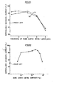
- Fig. 6A shows, in the same manner as in Fig. 2A, the emission current after the life test with the current density of 2.05 A/cm 2 as to cathodes according to this embodiment. As can be seen from this figure, lowering of the emission current in the cathodes of this embodiment is much suppressed as compared with the conventional cathode.
- Fig. 6B shows, in the same manner as in Fig. 2B, the emission current after the life tests of 6000 hr with various high current densities as to cathodes according to this embodiment.
- a rare earth metal of more than 0.05 wt.% contributes effectively to an improvement of the emission characteristics.
- the content of the rare earth metal oxide in the electron-emissive layer 2 is preferably in the range from 0.1 to 15 wt.% and more preferably in the range from 0.2 to 7 wt.%.
- the cathode containing Sc or Y was shown in this embodiment, La, Ce, Pr, Nd, Sm, Gd, Dy, Ho, Er or Tm may also be used.
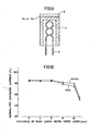
- Fig. 7 is an enlarged fragmentary sectional view schematically illustrating a cathode according to a still further embodiment of the present invention.
- the electron-emissive layer 2 comprises a first layer 2a formed on the base 1 and a second layer 2b formed on the first layer 2a.
- the first layer 2a contains not only alkaline earth metal oxide powder 21 but also rare earth metal oxide powder 22 of 0.2 to 20 wt.% containing Sc.
- the second layer 2b contains only alkaline earth metal oxide powder 21.
- each of the first and second layers 2a and 2b is formed to be approximately 40 ⁇ m in thickness.
- the cathode of this embodiment has a particularly stable initial electron-emission characteristic of 1 to 2 A/cm 2 under the normal condition at the operation temperature of 700 to 800°C.
- Fig. 8 shows a cathode according to a still further embodiment of the present invention.
- a sintered Ni powder layer 4 is formed on the surface of the base 1, and the electron-emissive layer 2 containing not only an alkaline earth metal oxide but also a rare earth metal oxide of 0.1 to 20 wt.% is formed on the sintered powder layer 4.
- the sintered Ni powder layer is formed in the following manner. Ni metal powder having a grain size of 3 to 5 ⁇ m is mixed with nitrocellulose lacquer and butyl acetate so that a suspension is prepared. This suspension is applied to the base 1 by a spray method so that the applied suspension has a thickness of approximately 30 ⁇ m. Then, the applied suspension is subjected to a heat treatment in an atmosphere of hydrogen at 1000°C for 10 minutes so that it is sintered.
- the sintered Ni powder layer 4 is porous and thus a part of the electron-emissive layer 2 applied thereon penetrates the sintered layer 4 to be in direct contact with the base 1. Even if the above described intermediate layer of Si0 2 , MgO or the like is formed in the region of contact with the base 1, lowering of the conductivity due to the formation of the intermediate layer can be prevented because a considerably large part of the electron-emissive layer 2 contacts the sintered layer 4.
- the thickness of the sintered Ni powder layer 4 is preferably 10 to 50 ⁇ m.
- a sintered layer of less than 10 ⁇ m is not effective because the intermediate layer of oxide might be formed on the side of the electron-emissive layer, exceeding the sintered layer.
- the thickness exceeds 50 ⁇ m the alkaline earth metal oxide can not be sufficiently penetrated into the sintered layer 4 and thus does not sufficiently come in contact with the base 1 containing the reducing element and, as a result, activation of the electron-emissive layer 2 can not be made in a satisfactory manner.
- Fig. 9 shows a cathode according to a still further embodiment of the present invention.
- a rare earth metal oxide layer 5a or a rare earth metal layer 5b is provided between the base 1 and the electron-emissive layer 2 made of an alkaline earth metal oxide.
- the rare earth metal oxide layer 5a or the rare earth metal layer 5b is formed by an electron beam evaporation method or a sputtering method prior to formation of the electron-emissive layer 2.
- the rare earth metal dissolves from the layer 5a or 5b into the base 1. Accordingly, even if oxygen produced by dissociation of BaO or other similar phenomenon is diffused into the base 1, segregation of Si0 2 and MgO in the interfacial region of the base 1 is suppressed because the rare earth metal dissolved in the base 1 reacts with the oxygen to form a rare earth metal oxide.
- the rare earth metal dissolved into the base 1 serves to strengthen the adhesion between the layer 5a or 5b and the base 1 and to prevent embrittlement of the base 1 containing Ni as a major element.
- Fig. 10 shows the emission current after the life test of 6000 hr with the current density of 2.05 A/cm with regard to cathodes provided with the rare earth metal oxide layer 5a of Sc 2 O 3 or Y 2 O 3 having various values of thickness.
- the cathode having the rare earth metal oxide layer of less than 10 ⁇ m in thickness shows an extremely excellent characteristic in prevention of lowering of the emission current as compared with a conventional cathode.
- the thickness of the rare earth metal oxide layer exceeds 10 ⁇ m, the reducing elements Si and Mg can not be diffused sufficiently from the base 1 into the electron-emissive layer 2 and separation of the rare earth metal oxide layer 5a from the base 1 may occur during the life test with the high current density.
- Fig. 11 shows, in the same manner as Fig. 10, the emission current with regard to cathodes provided with the rare earth metal layer 5b containing Sa or Y having various values of thickness.
- the cathode having the rare earth metal layer of less than 6 ⁇ m shows much less deterioration in the emission current as compared with a conventional cathode.
- the thickness of the rare earth metal layer exceeds 6 ⁇ m, the reducing elements Si and Mg can not be diffused sufficiently from the base 1 into the electron-emissive layer 2, causing the emission current to be considerably decreased.
- oxide layer 5a or the metal layer 5b containing Sc or Y was described in the embodiment in Fig. 9, an oxide or a metal containing at least one of the metals La, Ce, Pr, Nd, Sm, Gd, Dy, Ho, Er and Tm may also be used.
- a rare earth metal of 0.01 to 0.5 wt.% is contained in the base 1.
- An electron-emissive layer 2 made of an alkaline earth metal oxide containing at least Ba is formed directly on this base 1.
- Fig. 12 shows the relation between the rare earth metal content of Sc and/or Y in the base of the cathode according to this embodiment and the emission current after the life test of 6000 hr with the current density of 2.05 A/cm 2 .
- the cathode having the base 1 containing rare earth metal of 0.01 to 0.5 wt.% shows a by far smaller degree of lowering of the emission current compared with a conventional cathode. If the rare earth metal concentration is less than 0.01 wt.%, it can not serve to sufficiently suppress formation of oxide layers of SiO 2 and MgO in the interfacial layer of the base 1.
Landscapes
- Solid Thermionic Cathode (AREA)
Applications Claiming Priority (24)
| Application Number | Priority Date | Filing Date | Title |
|---|---|---|---|
| JP60160851A JPS6222347A (ja) | 1985-07-19 | 1985-07-19 | 電子管用陰極 |
| JP160851/85 | 1985-07-19 | ||
| JP229304/85 | 1985-10-14 | ||
| JP22930385A JPH0626096B2 (ja) | 1985-10-14 | 1985-10-14 | 電子菅用陰極 |
| JP60229302A JPS6288240A (ja) | 1985-10-14 | 1985-10-14 | 電子管用陰極 |
| JP60229304A JPS6288239A (ja) | 1985-10-14 | 1985-10-14 | 電子管用陰極 |
| JP229302/85 | 1985-10-14 | ||
| JP60231906A JPS6290821A (ja) | 1985-10-15 | 1985-10-15 | 電子管用陰極 |
| JP23190585A JPH0743995B2 (ja) | 1985-10-15 | 1985-10-15 | 電子管用陰極 |
| JP231904/85 | 1985-10-15 | ||
| JP23190485A JPH0782804B2 (ja) | 1985-10-15 | 1985-10-15 | 電子管用陰極 |
| JP231905/85 | 1985-10-15 | ||
| JP229303/85 | 1985-10-15 | ||
| JP231906/85 | 1985-10-15 | ||
| JP61008366A JPS62165833A (ja) | 1986-01-18 | 1986-01-18 | 電子管用陰極 |
| JP8365/86 | 1986-01-18 | ||
| JP61008365A JPS62165832A (ja) | 1986-01-18 | 1986-01-18 | 電子管用陰極 |
| JP8366/86 | 1986-01-18 | ||
| JP61035670A JPS62193031A (ja) | 1986-02-19 | 1986-02-19 | 電子管陰極 |
| JP35671/86 | 1986-02-19 | ||
| JP61035671A JPS62193032A (ja) | 1986-02-19 | 1986-02-19 | 電子管陰極 |
| JP35670/86 | 1986-02-19 | ||
| JP41050/86 | 1986-02-25 | ||
| JP4105086A JPH0782800B2 (ja) | 1986-02-25 | 1986-02-25 | 電子管陰極 |
Publications (3)
| Publication Number | Publication Date |
|---|---|
| EP0210805A2 true EP0210805A2 (fr) | 1987-02-04 |
| EP0210805A3 EP0210805A3 (en) | 1988-03-16 |
| EP0210805B1 EP0210805B1 (fr) | 1993-10-06 |
Family
ID=27583144
Family Applications (1)
| Application Number | Title | Priority Date | Filing Date |
|---|---|---|---|
| EP86305560A Expired - Lifetime EP0210805B1 (fr) | 1985-07-19 | 1986-07-18 | Cathode pour tube électronique |
Country Status (5)
| Country | Link |
|---|---|
| US (1) | US4797593A (fr) |
| EP (1) | EP0210805B1 (fr) |
| CN (1) | CN1004452B (fr) |
| CA (1) | CA1270890A (fr) |
| DE (1) | DE3689134T2 (fr) |
Cited By (16)
| Publication number | Priority date | Publication date | Assignee | Title |
|---|---|---|---|---|
| FR2616586A1 (fr) * | 1987-06-12 | 1988-12-16 | Mitsubishi Metal Corp | Cathode pour un tube electronique |
| EP0300568A1 (fr) * | 1987-07-23 | 1989-01-25 | Koninklijke Philips Electronics N.V. | Cathode à oxyde |
| EP0327074A3 (en) * | 1988-02-02 | 1989-10-18 | Mitsubishi Denki Kabushikikaisha | Cathode for a cathode ray tube |
| EP0373701A1 (fr) * | 1988-12-13 | 1990-06-20 | Koninklijke Philips Electronics N.V. | Cathode à oxyde |
| EP0330355A3 (en) * | 1988-02-23 | 1990-08-22 | Mitsubishi Denki Kabushiki Kaisha | Cathode for electron tube |
| EP0395157A1 (fr) * | 1989-04-28 | 1990-10-31 | Koninklijke Philips Electronics N.V. | Cathode à oxyde |
| NL9001956A (nl) * | 1989-09-07 | 1991-04-02 | Samsung Electronic Devices | Kathode voor een elektronenkanon, en werkwijze voor het vervaardigen daarvan. |
| EP0445956A3 (en) * | 1990-03-07 | 1991-11-21 | Mitsubishi Denki Kabushiki Kaisha | Electron tube cathode |
| FR2667721A1 (fr) * | 1990-10-05 | 1992-04-10 | Hitachi Ltd | Cathode pour tube electronique. |
| EP0482704A1 (fr) * | 1990-10-22 | 1992-04-29 | Koninklijke Philips Electronics N.V. | Cathode à oxyde |
| EP0516503A1 (fr) * | 1991-05-31 | 1992-12-02 | Thomson Tubes Electroniques | Cathode à oxydes et procédé de fabrication |
| EP0641006A1 (fr) * | 1993-08-24 | 1995-03-01 | Samsung Display Devices Co., Ltd. | Cathode pour un tube à électrons |
| GB2294155A (en) * | 1994-10-12 | 1996-04-17 | Samsung Display Devices Co Ltd | Cathodes for electron tubes |
| EP0794548A1 (fr) * | 1996-03-05 | 1997-09-10 | Thomson-Csf | Cathode thermoionique et son procédé de fabrication |
| NL1003086C2 (nl) * | 1995-10-30 | 1998-05-14 | Samsung Display Devices Co Ltd | Kathode voor een elektronenbuis. |
| EP1189253A1 (fr) * | 2000-09-14 | 2002-03-20 | Philips Corporate Intellectual Property GmbH | Tube à rayons cathodiques avec cathode à oxydes dopée |
Families Citing this family (35)
| Publication number | Priority date | Publication date | Assignee | Title |
|---|---|---|---|---|
| CA1270890A (fr) | 1985-07-19 | 1990-06-26 | Keiji Watanabe | Cathode de tube electronique |
| CN1040263C (zh) * | 1987-12-17 | 1998-10-14 | 三菱电机株式会社 | 电子管阴极 |
| NL8902793A (nl) * | 1989-11-13 | 1991-06-03 | Philips Nv | Scandaatkathode. |
| KR920009328B1 (ko) * | 1990-08-18 | 1992-10-15 | 삼성전관 주식회사 | 산화물 음극의 제조방법 |
| KR970009208B1 (en) * | 1993-07-26 | 1997-06-07 | Lg Electronics Inc | Cathode structure of electron gun for crt |
| DE69313845T2 (de) * | 1993-08-20 | 1998-04-02 | Samsung Display Devices Co Ltd | Oxydkathode für Elektronenröhre |
| KR100291903B1 (ko) * | 1993-08-23 | 2001-09-17 | 김순택 | 전자관용산화물음극 |
| US5744905A (en) * | 1994-12-23 | 1998-04-28 | Philips Electronics North America Corporation | Emission materials for discharge lamps and method for manufacturing electrode structures with such materials |
| US5982083A (en) * | 1995-02-23 | 1999-11-09 | Samsung Display Devices Co., Ltd. | Cathode for electron tube |
| JP2871516B2 (ja) * | 1995-03-22 | 1999-03-17 | 株式会社移動体通信先端技術研究所 | 酸化物超伝導薄膜装置 |
| US6037714A (en) * | 1995-09-19 | 2000-03-14 | Philips Electronics North America Corporation | Hollow electrodes for low pressure discharge lamps, particularly narrow diameter fluorescent and neon lamps and lamps containing the same |
| JPH09147735A (ja) * | 1995-09-21 | 1997-06-06 | Matsushita Electron Corp | 陰極線管用エミッタ材料及びその製造方法 |
| US5982097A (en) * | 1995-12-29 | 1999-11-09 | Philips Electronics North America Corporation | Hollow electrodes for low pressure discharge lamps, particularly narrow diameter fluorescent and neon lamps and lamps containing the same |
| US5898271A (en) * | 1996-04-25 | 1999-04-27 | U.S. Philips Corporation | Hollow cathodes with an I-beam or C-beam cross section for a plasma display device |
| US6133685A (en) * | 1996-07-05 | 2000-10-17 | Matsushita Electronics Corporation | Cathode-ray tube |
| US5925976A (en) * | 1996-11-12 | 1999-07-20 | Matsushita Electronics Corporation | Cathode for electron tube having specific emissive material |
| US6320333B1 (en) | 1997-02-07 | 2001-11-20 | Matsushita Electric Industrial Co., Ltd. | Color picture tube |
| JP3528526B2 (ja) | 1997-08-04 | 2004-05-17 | 松下電器産業株式会社 | カラー受像管装置 |
| JPH1167121A (ja) | 1997-08-27 | 1999-03-09 | Matsushita Electron Corp | 陰極線管 |
| JP2000357464A (ja) | 1999-06-14 | 2000-12-26 | Hitachi Ltd | 陰極線管 |
| JP2001345041A (ja) * | 2000-06-01 | 2001-12-14 | Mitsubishi Electric Corp | 電子管用陰極 |
| FR2810446A1 (fr) * | 2000-06-14 | 2001-12-21 | Thomson Tubes & Displays | Cathodes a oxyde amelioree et son procede de fabrication |
| ATE370515T1 (de) * | 2000-09-19 | 2007-09-15 | Koninkl Philips Electronics Nv | Oxidkathode |
| DE10121442B4 (de) * | 2000-09-19 | 2010-04-08 | Philips Intellectual Property & Standards Gmbh | Kathodenstrahlröhre mit Oxidkathode |
| WO2002025682A1 (fr) * | 2000-09-19 | 2002-03-28 | Koninklijke Philips Electronics N.V. | Tube cathodique comprenant une cathode constituee d'un materiau composite |
| JP2002334649A (ja) * | 2001-03-06 | 2002-11-22 | Nec Kansai Ltd | カソード構体、カソード構体の製造方法およびカラーブラウン管 |
| US6844203B2 (en) * | 2001-08-30 | 2005-01-18 | Micron Technology, Inc. | Gate oxides, and methods of forming |
| KR100490170B1 (ko) * | 2003-07-10 | 2005-05-16 | 엘지.필립스 디스플레이 주식회사 | 음극선관용 음극 |
| US20050037134A1 (en) * | 2003-08-12 | 2005-02-17 | Chunghwa Picture Tubes, Ltd. | Process of manufacturing micronized oxide cathode |
| CN101625950B (zh) * | 2009-08-03 | 2011-09-07 | 北京工业大学 | 含钇的压制型钡钨阴极及其制备方法 |
| EP3778939A1 (fr) * | 2012-05-29 | 2021-02-17 | Kabushiki Kaisha Toshiba | Procede de production d'une piece en alliage de tungstene |
| CN104733267A (zh) * | 2015-02-04 | 2015-06-24 | 中国科学技术大学 | 一种高电离率氧化物阴极等离子体源及其制备方法 |
| CN105679624B (zh) * | 2016-03-03 | 2017-08-25 | 宁波凯耀电器制造有限公司 | 一种耐轰击的电子发射材料及其制备方法 |
| CN110372382A (zh) * | 2019-07-15 | 2019-10-25 | 惠州学院 | 一种Ba3Gd4O9的制备方法 |
| CN115101395A (zh) * | 2022-07-11 | 2022-09-23 | 中国科学院空天信息创新研究院 | 直热式镍海绵氧化物阴极的制备方法及应用 |
Citations (9)
| Publication number | Priority date | Publication date | Assignee | Title |
|---|---|---|---|---|
| DE477232C (de) | 1922-06-23 | 1929-06-04 | Aeg | Aus schwer schmelzbarem Metall, insbesondere Wolfram, bestehende Gluehkathode fuer Elektronenroehren |
| DE880181C (de) | 1951-11-17 | 1953-06-18 | British Driver Harris Company | Elektrodenelement fuer Vakuumroehren |
| DE976106C (de) | 1954-11-19 | 1963-02-28 | Siemens Ag | Mittelbar geheizte Kathode fuer elektrische Entladungsgefaesse |
| DE2626700A1 (de) | 1975-06-20 | 1977-01-20 | Philips Nv | Hochdruckgasentladungslampe und verfahren zu ihrer herstellung |
| JPS535011A (en) | 1976-07-06 | 1978-01-18 | Sony Corp | Press cathode |
| GB1592502A (en) | 1976-11-30 | 1981-07-08 | Mitsubishi Electric Corp | Electrode of discharge lamp |
| JPS5920941A (ja) | 1982-07-27 | 1984-02-02 | Toshiba Corp | 陰極構体 |
| JPS59138033A (ja) | 1983-01-27 | 1984-08-08 | Toshiba Corp | 酸化物陰極構体 |
| US4797593A (en) | 1985-07-19 | 1989-01-10 | Mitsubishi Denki Kabushiki Kaisha | Cathode for electron tube |
Family Cites Families (16)
| Publication number | Priority date | Publication date | Assignee | Title |
|---|---|---|---|---|
| US1794298A (en) * | 1926-09-21 | 1931-02-24 | Gen Electric | Thermionic cathode |
| US3358178A (en) * | 1964-08-05 | 1967-12-12 | Figner Avraam Iljich | Metal-porous body having pores filled with barium scandate |
| US3719856A (en) * | 1971-05-19 | 1973-03-06 | O Koppius | Impregnants for dispenser cathodes |
| US3922428A (en) * | 1972-02-04 | 1975-11-25 | Spectra Mat Inc | Thermionic cathode comprising mixture of barium oxide, calcium oxide and samarium oxide |
| NL165880C (nl) * | 1975-02-21 | 1981-05-15 | Philips Nv | Naleveringskathode. |
| US4081713A (en) * | 1976-01-28 | 1978-03-28 | Hitachi, Ltd. | Directly heated oxide cathode |
| US4273683A (en) * | 1977-12-16 | 1981-06-16 | Hitachi, Ltd. | Oxide cathode and process for production thereof |
| JPS555661A (en) * | 1978-06-30 | 1980-01-16 | Tokyo Shibaura Electric Co | Ultrasoniccwave inspection device |
| JPS559828A (en) * | 1978-07-05 | 1980-01-24 | Dantoo Kk | Separating method of base film for heat-transfer paper in tile |
| US4636681A (en) * | 1978-07-27 | 1987-01-13 | Hitachi, Ltd. | Directly heated cathode |
| NL7905542A (nl) * | 1979-07-17 | 1981-01-20 | Philips Nv | Naleveringskathode. |
| GB2059676B (en) * | 1979-09-12 | 1983-07-20 | Hitachi Ltd | Oxide-coated cathodes |
| JPS5678066A (en) * | 1979-11-30 | 1981-06-26 | Matsushita Electric Ind Co Ltd | Alkaline battery |
| NL8201371A (nl) * | 1982-04-01 | 1983-11-01 | Philips Nv | Werkwijzen voor het vervaardigen van een naleveringskathode en naleveringskathode vervaardigd volgens deze werkwijzen. |
| NL8403032A (nl) * | 1984-10-05 | 1986-05-01 | Philips Nv | Werkwijze voor het vervaardigen van een scandaatnaleveringskathode, naleveringskathode vervaardigd met deze werkwijze. |
| KR900007751B1 (ko) * | 1985-05-25 | 1990-10-19 | 미쯔비시덴끼 가부시기가이샤 | 전자관 음극 및 그 제조방법 |
-
1986
- 1986-07-16 CA CA000513900A patent/CA1270890A/fr not_active Expired - Lifetime
- 1986-07-17 US US06/886,777 patent/US4797593A/en not_active Expired - Lifetime
- 1986-07-18 CN CN86104753.2A patent/CN1004452B/zh not_active Expired
- 1986-07-18 DE DE86305560T patent/DE3689134T2/de not_active Expired - Lifetime
- 1986-07-18 EP EP86305560A patent/EP0210805B1/fr not_active Expired - Lifetime
Patent Citations (9)
| Publication number | Priority date | Publication date | Assignee | Title |
|---|---|---|---|---|
| DE477232C (de) | 1922-06-23 | 1929-06-04 | Aeg | Aus schwer schmelzbarem Metall, insbesondere Wolfram, bestehende Gluehkathode fuer Elektronenroehren |
| DE880181C (de) | 1951-11-17 | 1953-06-18 | British Driver Harris Company | Elektrodenelement fuer Vakuumroehren |
| DE976106C (de) | 1954-11-19 | 1963-02-28 | Siemens Ag | Mittelbar geheizte Kathode fuer elektrische Entladungsgefaesse |
| DE2626700A1 (de) | 1975-06-20 | 1977-01-20 | Philips Nv | Hochdruckgasentladungslampe und verfahren zu ihrer herstellung |
| JPS535011A (en) | 1976-07-06 | 1978-01-18 | Sony Corp | Press cathode |
| GB1592502A (en) | 1976-11-30 | 1981-07-08 | Mitsubishi Electric Corp | Electrode of discharge lamp |
| JPS5920941A (ja) | 1982-07-27 | 1984-02-02 | Toshiba Corp | 陰極構体 |
| JPS59138033A (ja) | 1983-01-27 | 1984-08-08 | Toshiba Corp | 酸化物陰極構体 |
| US4797593A (en) | 1985-07-19 | 1989-01-10 | Mitsubishi Denki Kabushiki Kaisha | Cathode for electron tube |
Non-Patent Citations (1)
| Title |
|---|
| A. VAN OOSTROM ET AL., APPLICATIONS OF SURFACE SCIENCE, vol. 2, 1979, pages 173 - 186 |
Cited By (26)
| Publication number | Priority date | Publication date | Assignee | Title |
|---|---|---|---|---|
| US4980603A (en) * | 1987-06-12 | 1990-12-25 | Mitsubishi Kinzoku Kabushiki Kaisha | Cathode for an electron tube |
| FR2616586A1 (fr) * | 1987-06-12 | 1988-12-16 | Mitsubishi Metal Corp | Cathode pour un tube electronique |
| EP0300568A1 (fr) * | 1987-07-23 | 1989-01-25 | Koninklijke Philips Electronics N.V. | Cathode à oxyde |
| EP0327074A3 (en) * | 1988-02-02 | 1989-10-18 | Mitsubishi Denki Kabushikikaisha | Cathode for a cathode ray tube |
| EP0330355A3 (en) * | 1988-02-23 | 1990-08-22 | Mitsubishi Denki Kabushiki Kaisha | Cathode for electron tube |
| EP0373701A1 (fr) * | 1988-12-13 | 1990-06-20 | Koninklijke Philips Electronics N.V. | Cathode à oxyde |
| EP0395157A1 (fr) * | 1989-04-28 | 1990-10-31 | Koninklijke Philips Electronics N.V. | Cathode à oxyde |
| CN1041870C (zh) * | 1989-04-28 | 1999-01-27 | 皇家菲利浦电子有限公司 | 氧化物阴极 |
| NL9001956A (nl) * | 1989-09-07 | 1991-04-02 | Samsung Electronic Devices | Kathode voor een elektronenkanon, en werkwijze voor het vervaardigen daarvan. |
| EP0445956A3 (en) * | 1990-03-07 | 1991-11-21 | Mitsubishi Denki Kabushiki Kaisha | Electron tube cathode |
| US5118984A (en) * | 1990-03-07 | 1992-06-02 | Mitsubishi Denki Kabushiki Kaisha | Electron tube cathode |
| FR2667721A1 (fr) * | 1990-10-05 | 1992-04-10 | Hitachi Ltd | Cathode pour tube electronique. |
| US5216320A (en) * | 1990-10-05 | 1993-06-01 | Hitachi, Ltd. | Cathode for electron tube |
| EP0482704A1 (fr) * | 1990-10-22 | 1992-04-29 | Koninklijke Philips Electronics N.V. | Cathode à oxyde |
| US5347194A (en) * | 1990-10-22 | 1994-09-13 | U.S. Philips Corporation | Oxide cathode with rare earth addition |
| EP0516503A1 (fr) * | 1991-05-31 | 1992-12-02 | Thomson Tubes Electroniques | Cathode à oxydes et procédé de fabrication |
| FR2677169A1 (fr) * | 1991-05-31 | 1992-12-04 | Thomson Tubes Electroniques | Cathode a oxydes et procede de fabrication. |
| EP0641006A1 (fr) * | 1993-08-24 | 1995-03-01 | Samsung Display Devices Co., Ltd. | Cathode pour un tube à électrons |
| GB2294155A (en) * | 1994-10-12 | 1996-04-17 | Samsung Display Devices Co Ltd | Cathodes for electron tubes |
| NL9500286A (nl) * | 1994-10-12 | 1996-05-01 | Samsung Display Devices Co Ltd | Cathode voor electronenbuis. |
| GB2294155B (en) * | 1994-10-12 | 1999-03-03 | Samsung Display Devices Co Ltd | Cathode for electron tube |
| NL1003086C2 (nl) * | 1995-10-30 | 1998-05-14 | Samsung Display Devices Co Ltd | Kathode voor een elektronenbuis. |
| EP0794548A1 (fr) * | 1996-03-05 | 1997-09-10 | Thomson-Csf | Cathode thermoionique et son procédé de fabrication |
| FR2745951A1 (fr) * | 1996-03-05 | 1997-09-12 | Thomson Csf | Cathode thermoionique et son procede de fabrication |
| US5828165A (en) * | 1996-03-05 | 1998-10-27 | Thomson-Csf | Thermionic cathode for electron tubes and method for the manufacture thereof |
| EP1189253A1 (fr) * | 2000-09-14 | 2002-03-20 | Philips Corporate Intellectual Property GmbH | Tube à rayons cathodiques avec cathode à oxydes dopée |
Also Published As
| Publication number | Publication date |
|---|---|
| CN86104753A (zh) | 1987-01-14 |
| US4797593A (en) | 1989-01-10 |
| DE3689134D1 (de) | 1993-11-11 |
| EP0210805B1 (fr) | 1993-10-06 |
| CA1270890A (fr) | 1990-06-26 |
| DE3689134T2 (de) | 1994-03-03 |
| EP0210805A3 (en) | 1988-03-16 |
| CN1004452B (zh) | 1989-06-07 |
Similar Documents
| Publication | Publication Date | Title |
|---|---|---|
| EP0210805A2 (fr) | Cathode pour tube électronique | |
| US4924137A (en) | Cathode for electron tube | |
| CA2037675C (fr) | Cathode de tube electronique | |
| EP0204477B1 (fr) | Cathode pour tube électronique et procédé de fabrication du même type | |
| JPS6222347A (ja) | 電子管用陰極 | |
| US4980603A (en) | Cathode for an electron tube | |
| CA1101479A (fr) | Traduction non-disponible | |
| US5314364A (en) | Scandate cathode and methods of making it | |
| US5064397A (en) | Method of manufacturing scandate cathode with scandium oxide film | |
| KR100244175B1 (ko) | 전자관용 음극 | |
| KR900003175B1 (ko) | 전자관용음극 | |
| US5747921A (en) | Impregnation type cathode for a cathodic ray tube | |
| US4146393A (en) | Base metal plate materials for directly heated oxide cathode | |
| JP2718389B2 (ja) | 電子管用陰極 | |
| JPS6290821A (ja) | 電子管用陰極 | |
| US6798128B2 (en) | Cathode-ray tube cathode and alloy therefor | |
| JPS6288239A (ja) | 電子管用陰極 | |
| JPS62165832A (ja) | 電子管用陰極 | |
| JPH0775140B2 (ja) | 電子管用陰極 | |
| JPS6290819A (ja) | 電子管用陰極 | |
| JP2003007194A (ja) | 含浸型陰極およびその製造方法 | |
| JPH0626096B2 (ja) | 電子菅用陰極 | |
| JPS62165833A (ja) | 電子管用陰極 | |
| JPH06105585B2 (ja) | 電子管用陰極 | |
| JPH0743995B2 (ja) | 電子管用陰極 |
Legal Events
| Date | Code | Title | Description |
|---|---|---|---|
| PUAI | Public reference made under article 153(3) epc to a published international application that has entered the european phase |
Free format text: ORIGINAL CODE: 0009012 |
|
| AK | Designated contracting states |
Kind code of ref document: A2 Designated state(s): DE FR GB IT NL |
|
| PUAL | Search report despatched |
Free format text: ORIGINAL CODE: 0009013 |
|
| AK | Designated contracting states |
Kind code of ref document: A3 Designated state(s): DE FR GB IT NL |
|
| 17P | Request for examination filed |
Effective date: 19880813 |
|
| 17Q | First examination report despatched |
Effective date: 19890712 |
|
| GRAA | (expected) grant |
Free format text: ORIGINAL CODE: 0009210 |
|
| AK | Designated contracting states |
Kind code of ref document: B1 Designated state(s): DE FR GB IT NL |
|
| REF | Corresponds to: |
Ref document number: 3689134 Country of ref document: DE Date of ref document: 19931111 |
|
| ITF | It: translation for a ep patent filed | ||
| ET | Fr: translation filed | ||
| PLBE | No opposition filed within time limit |
Free format text: ORIGINAL CODE: 0009261 |
|
| STAA | Information on the status of an ep patent application or granted ep patent |
Free format text: STATUS: NO OPPOSITION FILED WITHIN TIME LIMIT |
|
| 26N | No opposition filed | ||
| REG | Reference to a national code |
Ref country code: GB Ref legal event code: IF02 |
|
| REG | Reference to a national code |
Ref country code: GB Ref legal event code: 747 Free format text: APPLICATION WITHDRAWN |
|
| PGFP | Annual fee paid to national office [announced via postgrant information from national office to epo] |
Ref country code: NL Payment date: 20050703 Year of fee payment: 20 |
|
| PGFP | Annual fee paid to national office [announced via postgrant information from national office to epo] |
Ref country code: FR Payment date: 20050708 Year of fee payment: 20 |
|
| PGFP | Annual fee paid to national office [announced via postgrant information from national office to epo] |
Ref country code: GB Payment date: 20050713 Year of fee payment: 20 |
|
| PGFP | Annual fee paid to national office [announced via postgrant information from national office to epo] |
Ref country code: DE Payment date: 20050714 Year of fee payment: 20 |
|
| PGFP | Annual fee paid to national office [announced via postgrant information from national office to epo] |
Ref country code: IT Payment date: 20050728 Year of fee payment: 20 |
|
| PG25 | Lapsed in a contracting state [announced via postgrant information from national office to epo] |
Ref country code: GB Free format text: LAPSE BECAUSE OF EXPIRATION OF PROTECTION Effective date: 20060717 |
|
| PG25 | Lapsed in a contracting state [announced via postgrant information from national office to epo] |
Ref country code: NL Free format text: LAPSE BECAUSE OF EXPIRATION OF PROTECTION Effective date: 20060718 |
|
| REG | Reference to a national code |
Ref country code: GB Ref legal event code: PE20 |
|
| NLV7 | Nl: ceased due to reaching the maximum lifetime of a patent |
Effective date: 20060718 |