EP0212314B1 - Dispositif d'écoulement capillaire - Google Patents
Dispositif d'écoulement capillaire Download PDFInfo
- Publication number
- EP0212314B1 EP0212314B1 EP19860110184 EP86110184A EP0212314B1 EP 0212314 B1 EP0212314 B1 EP 0212314B1 EP 19860110184 EP19860110184 EP 19860110184 EP 86110184 A EP86110184 A EP 86110184A EP 0212314 B1 EP0212314 B1 EP 0212314B1
- Authority
- EP
- European Patent Office
- Prior art keywords
- capillary
- sample
- reagent
- chamber
- pathway
- Prior art date
- Legal status (The legal status is an assumption and is not a legal conclusion. Google has not performed a legal analysis and makes no representation as to the accuracy of the status listed.)
- Expired - Lifetime
Links
Images

Classifications
-
- G—PHYSICS
- G01—MEASURING; TESTING
- G01N—INVESTIGATING OR ANALYSING MATERIALS BY DETERMINING THEIR CHEMICAL OR PHYSICAL PROPERTIES
- G01N33/00—Investigating or analysing materials by specific methods not covered by groups G01N1/00 - G01N31/00
- G01N33/48—Biological material, e.g. blood, urine; Haemocytometers
- G01N33/483—Physical analysis of biological material
- G01N33/487—Physical analysis of biological material of liquid biological material
- G01N33/49—Blood
- G01N33/4905—Determining clotting time of blood
-
- B—PERFORMING OPERATIONS; TRANSPORTING
- B01—PHYSICAL OR CHEMICAL PROCESSES OR APPARATUS IN GENERAL
- B01F—MIXING, e.g. DISSOLVING, EMULSIFYING OR DISPERSING
- B01F25/00—Flow mixers; Mixers for falling materials, e.g. solid particles
- B01F25/40—Static mixers
- B01F25/42—Static mixers in which the mixing is affected by moving the components jointly in changing directions, e.g. in tubes provided with baffles or obstructions
- B01F25/43—Mixing tubes, e.g. wherein the material is moved in a radial or partly reversed direction
- B01F25/431—Straight mixing tubes with baffles or obstructions that do not cause substantial pressure drop; Baffles therefor
- B01F25/4316—Straight mixing tubes with baffles or obstructions that do not cause substantial pressure drop; Baffles therefor the baffles being flat pieces of material, e.g. intermeshing, fixed to the wall or fixed on a central rod
-
- B—PERFORMING OPERATIONS; TRANSPORTING
- B01—PHYSICAL OR CHEMICAL PROCESSES OR APPARATUS IN GENERAL
- B01F—MIXING, e.g. DISSOLVING, EMULSIFYING OR DISPERSING
- B01F25/00—Flow mixers; Mixers for falling materials, e.g. solid particles
- B01F25/40—Static mixers
- B01F25/42—Static mixers in which the mixing is affected by moving the components jointly in changing directions, e.g. in tubes provided with baffles or obstructions
- B01F25/43—Mixing tubes, e.g. wherein the material is moved in a radial or partly reversed direction
- B01F25/433—Mixing tubes wherein the shape of the tube influences the mixing, e.g. mixing tubes with varying cross-section or provided with inwardly extending profiles
-
- B—PERFORMING OPERATIONS; TRANSPORTING
- B01—PHYSICAL OR CHEMICAL PROCESSES OR APPARATUS IN GENERAL
- B01F—MIXING, e.g. DISSOLVING, EMULSIFYING OR DISPERSING
- B01F25/00—Flow mixers; Mixers for falling materials, e.g. solid particles
- B01F25/40—Static mixers
- B01F25/42—Static mixers in which the mixing is affected by moving the components jointly in changing directions, e.g. in tubes provided with baffles or obstructions
- B01F25/43—Mixing tubes, e.g. wherein the material is moved in a radial or partly reversed direction
- B01F25/433—Mixing tubes wherein the shape of the tube influences the mixing, e.g. mixing tubes with varying cross-section or provided with inwardly extending profiles
- B01F25/4338—Mixers with a succession of converging-diverging cross-sections, i.e. undulating cross-section
-
- B—PERFORMING OPERATIONS; TRANSPORTING
- B01—PHYSICAL OR CHEMICAL PROCESSES OR APPARATUS IN GENERAL
- B01F—MIXING, e.g. DISSOLVING, EMULSIFYING OR DISPERSING
- B01F33/00—Other mixers; Mixing plants; Combinations of mixers
- B01F33/30—Micromixers
-
- B—PERFORMING OPERATIONS; TRANSPORTING
- B01—PHYSICAL OR CHEMICAL PROCESSES OR APPARATUS IN GENERAL
- B01F—MIXING, e.g. DISSOLVING, EMULSIFYING OR DISPERSING
- B01F35/00—Accessories for mixers; Auxiliary operations or auxiliary devices; Parts or details of general application
- B01F35/71—Feed mechanisms
- B01F35/717—Feed mechanisms characterised by the means for feeding the components to the mixer
- B01F35/7172—Feed mechanisms characterised by the means for feeding the components to the mixer using capillary forces
-
- B—PERFORMING OPERATIONS; TRANSPORTING
- B01—PHYSICAL OR CHEMICAL PROCESSES OR APPARATUS IN GENERAL
- B01L—CHEMICAL OR PHYSICAL LABORATORY APPARATUS FOR GENERAL USE
- B01L3/00—Containers or dishes for laboratory use, e.g. laboratory glassware; Droppers
- B01L3/50—Containers for the purpose of retaining a material to be analysed, e.g. test tubes
- B01L3/502—Containers for the purpose of retaining a material to be analysed, e.g. test tubes with fluid transport, e.g. in multi-compartment structures
- B01L3/5027—Containers for the purpose of retaining a material to be analysed, e.g. test tubes with fluid transport, e.g. in multi-compartment structures by integrated microfluidic structures, i.e. dimensions of channels and chambers are such that surface tension forces are important, e.g. lab-on-a-chip
- B01L3/50273—Containers for the purpose of retaining a material to be analysed, e.g. test tubes with fluid transport, e.g. in multi-compartment structures by integrated microfluidic structures, i.e. dimensions of channels and chambers are such that surface tension forces are important, e.g. lab-on-a-chip characterised by the means or forces applied to move the fluids
-
- B—PERFORMING OPERATIONS; TRANSPORTING
- B01—PHYSICAL OR CHEMICAL PROCESSES OR APPARATUS IN GENERAL
- B01L—CHEMICAL OR PHYSICAL LABORATORY APPARATUS FOR GENERAL USE
- B01L3/00—Containers or dishes for laboratory use, e.g. laboratory glassware; Droppers
- B01L3/50—Containers for the purpose of retaining a material to be analysed, e.g. test tubes
- B01L3/502—Containers for the purpose of retaining a material to be analysed, e.g. test tubes with fluid transport, e.g. in multi-compartment structures
- B01L3/5027—Containers for the purpose of retaining a material to be analysed, e.g. test tubes with fluid transport, e.g. in multi-compartment structures by integrated microfluidic structures, i.e. dimensions of channels and chambers are such that surface tension forces are important, e.g. lab-on-a-chip
- B01L3/502746—Containers for the purpose of retaining a material to be analysed, e.g. test tubes with fluid transport, e.g. in multi-compartment structures by integrated microfluidic structures, i.e. dimensions of channels and chambers are such that surface tension forces are important, e.g. lab-on-a-chip characterised by the means for controlling flow resistance, e.g. flow controllers, baffles or throttle valves
-
- B—PERFORMING OPERATIONS; TRANSPORTING
- B29—WORKING OF PLASTICS; WORKING OF SUBSTANCES IN A PLASTIC STATE IN GENERAL
- B29C—SHAPING OR JOINING OF PLASTICS; SHAPING OF MATERIAL IN A PLASTIC STATE, NOT OTHERWISE PROVIDED FOR; AFTER-TREATMENT OF THE SHAPED PRODUCTS, e.g. REPAIRING
- B29C65/00—Joining or sealing of preformed parts, e.g. welding of plastics materials; Apparatus therefor
- B29C65/02—Joining or sealing of preformed parts, e.g. welding of plastics materials; Apparatus therefor by heating, with or without pressure
- B29C65/08—Joining or sealing of preformed parts, e.g. welding of plastics materials; Apparatus therefor by heating, with or without pressure using ultrasonic vibrations
-
- B—PERFORMING OPERATIONS; TRANSPORTING
- B29—WORKING OF PLASTICS; WORKING OF SUBSTANCES IN A PLASTIC STATE IN GENERAL
- B29C—SHAPING OR JOINING OF PLASTICS; SHAPING OF MATERIAL IN A PLASTIC STATE, NOT OTHERWISE PROVIDED FOR; AFTER-TREATMENT OF THE SHAPED PRODUCTS, e.g. REPAIRING
- B29C66/00—General aspects of processes or apparatus for joining preformed parts
- B29C66/01—General aspects dealing with the joint area or with the area to be joined
- B29C66/05—Particular design of joint configurations
- B29C66/302—Particular design of joint configurations the area to be joined comprising melt initiators
- B29C66/3022—Particular design of joint configurations the area to be joined comprising melt initiators said melt initiators being integral with at least one of the parts to be joined
- B29C66/30223—Particular design of joint configurations the area to be joined comprising melt initiators said melt initiators being integral with at least one of the parts to be joined said melt initiators being rib-like
-
- B—PERFORMING OPERATIONS; TRANSPORTING
- B29—WORKING OF PLASTICS; WORKING OF SUBSTANCES IN A PLASTIC STATE IN GENERAL
- B29C—SHAPING OR JOINING OF PLASTICS; SHAPING OF MATERIAL IN A PLASTIC STATE, NOT OTHERWISE PROVIDED FOR; AFTER-TREATMENT OF THE SHAPED PRODUCTS, e.g. REPAIRING
- B29C66/00—General aspects of processes or apparatus for joining preformed parts
- B29C66/50—General aspects of joining tubular articles; General aspects of joining long products, i.e. bars or profiled elements; General aspects of joining single elements to tubular articles, hollow articles or bars; General aspects of joining several hollow-preforms to form hollow or tubular articles
- B29C66/51—Joining tubular articles, profiled elements or bars; Joining single elements to tubular articles, hollow articles or bars; Joining several hollow-preforms to form hollow or tubular articles
- B29C66/54—Joining several hollow-preforms, e.g. half-shells, to form hollow articles, e.g. for making balls, containers; Joining several hollow-preforms, e.g. half-cylinders, to form tubular articles
-
- B—PERFORMING OPERATIONS; TRANSPORTING
- B29—WORKING OF PLASTICS; WORKING OF SUBSTANCES IN A PLASTIC STATE IN GENERAL
- B29C—SHAPING OR JOINING OF PLASTICS; SHAPING OF MATERIAL IN A PLASTIC STATE, NOT OTHERWISE PROVIDED FOR; AFTER-TREATMENT OF THE SHAPED PRODUCTS, e.g. REPAIRING
- B29C66/00—General aspects of processes or apparatus for joining preformed parts
- B29C66/70—General aspects of processes or apparatus for joining preformed parts characterised by the composition, physical properties or the structure of the material of the parts to be joined; Joining with non-plastics material
- B29C66/71—General aspects of processes or apparatus for joining preformed parts characterised by the composition, physical properties or the structure of the material of the parts to be joined; Joining with non-plastics material characterised by the composition of the plastics material of the parts to be joined
-
- G—PHYSICS
- G01—MEASURING; TESTING
- G01N—INVESTIGATING OR ANALYSING MATERIALS BY DETERMINING THEIR CHEMICAL OR PHYSICAL PROPERTIES
- G01N21/00—Investigating or analysing materials by the use of optical means, i.e. using sub-millimetre waves, infrared, visible or ultraviolet light
- G01N21/75—Systems in which material is subjected to a chemical reaction, the progress or the result of the reaction being investigated
- G01N21/77—Systems in which material is subjected to a chemical reaction, the progress or the result of the reaction being investigated by observing the effect on a chemical indicator
- G01N21/82—Systems in which material is subjected to a chemical reaction, the progress or the result of the reaction being investigated by observing the effect on a chemical indicator producing a precipitate or turbidity
-
- B—PERFORMING OPERATIONS; TRANSPORTING
- B01—PHYSICAL OR CHEMICAL PROCESSES OR APPARATUS IN GENERAL
- B01F—MIXING, e.g. DISSOLVING, EMULSIFYING OR DISPERSING
- B01F21/00—Dissolving
-
- B—PERFORMING OPERATIONS; TRANSPORTING
- B01—PHYSICAL OR CHEMICAL PROCESSES OR APPARATUS IN GENERAL
- B01F—MIXING, e.g. DISSOLVING, EMULSIFYING OR DISPERSING
- B01F2101/00—Mixing characterised by the nature of the mixed materials or by the application field
- B01F2101/23—Mixing of laboratory samples e.g. in preparation of analysing or testing properties of materials
-
- B—PERFORMING OPERATIONS; TRANSPORTING
- B01—PHYSICAL OR CHEMICAL PROCESSES OR APPARATUS IN GENERAL
- B01F—MIXING, e.g. DISSOLVING, EMULSIFYING OR DISPERSING
- B01F23/00—Mixing according to the phases to be mixed, e.g. dispersing or emulsifying
- B01F23/50—Mixing liquids with solids
- B01F23/56—Mixing liquids with solids by introducing solids in liquids, e.g. dispersing or dissolving
-
- B—PERFORMING OPERATIONS; TRANSPORTING
- B01—PHYSICAL OR CHEMICAL PROCESSES OR APPARATUS IN GENERAL
- B01L—CHEMICAL OR PHYSICAL LABORATORY APPARATUS FOR GENERAL USE
- B01L2200/00—Solutions for specific problems relating to chemical or physical laboratory apparatus
- B01L2200/06—Fluid handling related problems
- B01L2200/0689—Sealing
-
- B—PERFORMING OPERATIONS; TRANSPORTING
- B01—PHYSICAL OR CHEMICAL PROCESSES OR APPARATUS IN GENERAL
- B01L—CHEMICAL OR PHYSICAL LABORATORY APPARATUS FOR GENERAL USE
- B01L2300/00—Additional constructional details
- B01L2300/08—Geometry, shape and general structure
- B01L2300/0809—Geometry, shape and general structure rectangular shaped
- B01L2300/0816—Cards, e.g. flat sample carriers usually with flow in two horizontal directions
-
- B—PERFORMING OPERATIONS; TRANSPORTING
- B01—PHYSICAL OR CHEMICAL PROCESSES OR APPARATUS IN GENERAL
- B01L—CHEMICAL OR PHYSICAL LABORATORY APPARATUS FOR GENERAL USE
- B01L2300/00—Additional constructional details
- B01L2300/08—Geometry, shape and general structure
- B01L2300/0861—Configuration of multiple channels and/or chambers in a single devices
-
- B—PERFORMING OPERATIONS; TRANSPORTING
- B01—PHYSICAL OR CHEMICAL PROCESSES OR APPARATUS IN GENERAL
- B01L—CHEMICAL OR PHYSICAL LABORATORY APPARATUS FOR GENERAL USE
- B01L2300/00—Additional constructional details
- B01L2300/08—Geometry, shape and general structure
- B01L2300/0887—Laminated structure
-
- B—PERFORMING OPERATIONS; TRANSPORTING
- B01—PHYSICAL OR CHEMICAL PROCESSES OR APPARATUS IN GENERAL
- B01L—CHEMICAL OR PHYSICAL LABORATORY APPARATUS FOR GENERAL USE
- B01L2400/00—Moving or stopping fluids
- B01L2400/04—Moving fluids with specific forces or mechanical means
- B01L2400/0403—Moving fluids with specific forces or mechanical means specific forces
- B01L2400/0406—Moving fluids with specific forces or mechanical means specific forces capillary forces
-
- B—PERFORMING OPERATIONS; TRANSPORTING
- B01—PHYSICAL OR CHEMICAL PROCESSES OR APPARATUS IN GENERAL
- B01L—CHEMICAL OR PHYSICAL LABORATORY APPARATUS FOR GENERAL USE
- B01L2400/00—Moving or stopping fluids
- B01L2400/06—Valves, specific forms thereof
- B01L2400/0694—Valves, specific forms thereof vents used to stop and induce flow, backpressure valves
-
- B—PERFORMING OPERATIONS; TRANSPORTING
- B29—WORKING OF PLASTICS; WORKING OF SUBSTANCES IN A PLASTIC STATE IN GENERAL
- B29C—SHAPING OR JOINING OF PLASTICS; SHAPING OF MATERIAL IN A PLASTIC STATE, NOT OTHERWISE PROVIDED FOR; AFTER-TREATMENT OF THE SHAPED PRODUCTS, e.g. REPAIRING
- B29C45/00—Injection moulding, i.e. forcing the required volume of moulding material through a nozzle into a closed mould; Apparatus therefor
-
- B—PERFORMING OPERATIONS; TRANSPORTING
- B29—WORKING OF PLASTICS; WORKING OF SUBSTANCES IN A PLASTIC STATE IN GENERAL
- B29C—SHAPING OR JOINING OF PLASTICS; SHAPING OF MATERIAL IN A PLASTIC STATE, NOT OTHERWISE PROVIDED FOR; AFTER-TREATMENT OF THE SHAPED PRODUCTS, e.g. REPAIRING
- B29C59/00—Surface shaping of articles, e.g. embossing; Apparatus therefor
- B29C59/16—Surface shaping of articles, e.g. embossing; Apparatus therefor by wave energy or particle radiation, e.g. infrared heating
-
- B—PERFORMING OPERATIONS; TRANSPORTING
- B29—WORKING OF PLASTICS; WORKING OF SUBSTANCES IN A PLASTIC STATE IN GENERAL
- B29C—SHAPING OR JOINING OF PLASTICS; SHAPING OF MATERIAL IN A PLASTIC STATE, NOT OTHERWISE PROVIDED FOR; AFTER-TREATMENT OF THE SHAPED PRODUCTS, e.g. REPAIRING
- B29C65/00—Joining or sealing of preformed parts, e.g. welding of plastics materials; Apparatus therefor
- B29C65/48—Joining or sealing of preformed parts, e.g. welding of plastics materials; Apparatus therefor using adhesives, i.e. using supplementary joining material; solvent bonding
- B29C65/4895—Solvent bonding, i.e. the surfaces of the parts to be joined being treated with solvents, swelling or softening agents, without adhesives
-
- B—PERFORMING OPERATIONS; TRANSPORTING
- B29—WORKING OF PLASTICS; WORKING OF SUBSTANCES IN A PLASTIC STATE IN GENERAL
- B29C—SHAPING OR JOINING OF PLASTICS; SHAPING OF MATERIAL IN A PLASTIC STATE, NOT OTHERWISE PROVIDED FOR; AFTER-TREATMENT OF THE SHAPED PRODUCTS, e.g. REPAIRING
- B29C66/00—General aspects of processes or apparatus for joining preformed parts
- B29C66/90—Measuring or controlling the joining process
- B29C66/95—Measuring or controlling the joining process by measuring or controlling specific variables not covered by groups B29C66/91 - B29C66/94
- B29C66/951—Measuring or controlling the joining process by measuring or controlling specific variables not covered by groups B29C66/91 - B29C66/94 by measuring or controlling the vibration frequency and/or the vibration amplitude of vibrating joining tools, e.g. of ultrasonic welding tools
- B29C66/9513—Measuring or controlling the joining process by measuring or controlling specific variables not covered by groups B29C66/91 - B29C66/94 by measuring or controlling the vibration frequency and/or the vibration amplitude of vibrating joining tools, e.g. of ultrasonic welding tools characterised by specific vibration frequency values or ranges
-
- B—PERFORMING OPERATIONS; TRANSPORTING
- B29—WORKING OF PLASTICS; WORKING OF SUBSTANCES IN A PLASTIC STATE IN GENERAL
- B29K—INDEXING SCHEME ASSOCIATED WITH SUBCLASSES B29B, B29C OR B29D, RELATING TO MOULDING MATERIALS OR TO MATERIALS FOR MOULDS, REINFORCEMENTS, FILLERS OR PREFORMED PARTS, e.g. INSERTS
- B29K2055/00—Use of specific polymers obtained by polymerisation reactions only involving carbon-to-carbon unsaturated bonds, not provided for in a single one of main groups B29K2023/00 - B29K2049/00, e.g. having a vinyl group, as moulding material
- B29K2055/02—ABS polymers, i.e. acrylonitrile-butadiene-styrene polymers
-
- B—PERFORMING OPERATIONS; TRANSPORTING
- B29—WORKING OF PLASTICS; WORKING OF SUBSTANCES IN A PLASTIC STATE IN GENERAL
- B29L—INDEXING SCHEME ASSOCIATED WITH SUBCLASS B29C, RELATING TO PARTICULAR ARTICLES
- B29L2031/00—Other particular articles
- B29L2031/756—Microarticles, nanoarticles
-
- G—PHYSICS
- G01—MEASURING; TESTING
- G01N—INVESTIGATING OR ANALYSING MATERIALS BY DETERMINING THEIR CHEMICAL OR PHYSICAL PROPERTIES
- G01N15/00—Investigating characteristics of particles; Investigating permeability, pore-volume or surface-area of porous materials
- G01N15/10—Investigating individual particles
- G01N15/1012—Calibrating particle analysers; References therefor
- G01N2015/1016—Particle flow simulating, e.g. liquid crystal cell
-
- G—PHYSICS
- G01—MEASURING; TESTING
- G01N—INVESTIGATING OR ANALYSING MATERIALS BY DETERMINING THEIR CHEMICAL OR PHYSICAL PROPERTIES
- G01N21/00—Investigating or analysing materials by the use of optical means, i.e. using sub-millimetre waves, infrared, visible or ultraviolet light
- G01N21/01—Arrangements or apparatus for facilitating the optical investigation
- G01N21/03—Cuvette constructions
- G01N2021/0346—Capillary cells; Microcells
-
- G—PHYSICS
- G01—MEASURING; TESTING
- G01N—INVESTIGATING OR ANALYSING MATERIALS BY DETERMINING THEIR CHEMICAL OR PHYSICAL PROPERTIES
- G01N35/00—Automatic analysis not limited to methods or materials provided for in any single one of groups G01N1/00 - G01N33/00; Handling materials therefor
- G01N2035/00465—Separating and mixing arrangements
- G01N2035/00514—Stationary mixing elements
-
- G—PHYSICS
- G01—MEASURING; TESTING
- G01N—INVESTIGATING OR ANALYSING MATERIALS BY DETERMINING THEIR CHEMICAL OR PHYSICAL PROPERTIES
- G01N21/00—Investigating or analysing materials by the use of optical means, i.e. using sub-millimetre waves, infrared, visible or ultraviolet light
- G01N21/17—Systems in which incident light is modified in accordance with the properties of the material investigated
- G01N21/47—Scattering, i.e. diffuse reflection
-
- G—PHYSICS
- G01—MEASURING; TESTING
- G01N—INVESTIGATING OR ANALYSING MATERIALS BY DETERMINING THEIR CHEMICAL OR PHYSICAL PROPERTIES
- G01N21/00—Investigating or analysing materials by the use of optical means, i.e. using sub-millimetre waves, infrared, visible or ultraviolet light
- G01N21/17—Systems in which incident light is modified in accordance with the properties of the material investigated
- G01N21/47—Scattering, i.e. diffuse reflection
- G01N21/49—Scattering, i.e. diffuse reflection within a body or fluid
-
- G—PHYSICS
- G01—MEASURING; TESTING
- G01N—INVESTIGATING OR ANALYSING MATERIALS BY DETERMINING THEIR CHEMICAL OR PHYSICAL PROPERTIES
- G01N33/00—Investigating or analysing materials by specific methods not covered by groups G01N1/00 - G01N31/00
- G01N33/48—Biological material, e.g. blood, urine; Haemocytometers
- G01N33/50—Chemical analysis of biological material, e.g. blood, urine; Testing involving biospecific ligand binding methods; Immunological testing
- G01N33/53—Immunoassay; Biospecific binding assay; Materials therefor
- G01N33/543—Immunoassay; Biospecific binding assay; Materials therefor with an insoluble carrier for immobilising immunochemicals
- G01N33/54366—Apparatus specially adapted for solid-phase testing
-
- Y—GENERAL TAGGING OF NEW TECHNOLOGICAL DEVELOPMENTS; GENERAL TAGGING OF CROSS-SECTIONAL TECHNOLOGIES SPANNING OVER SEVERAL SECTIONS OF THE IPC; TECHNICAL SUBJECTS COVERED BY FORMER USPC CROSS-REFERENCE ART COLLECTIONS [XRACs] AND DIGESTS
- Y10—TECHNICAL SUBJECTS COVERED BY FORMER USPC
- Y10S—TECHNICAL SUBJECTS COVERED BY FORMER USPC CROSS-REFERENCE ART COLLECTIONS [XRACs] AND DIGESTS
- Y10S366/00—Agitating
- Y10S366/03—Micromixers: variable geometry from the pathway influences mixing/agitation of non-laminar fluid flow
-
- Y—GENERAL TAGGING OF NEW TECHNOLOGICAL DEVELOPMENTS; GENERAL TAGGING OF CROSS-SECTIONAL TECHNOLOGIES SPANNING OVER SEVERAL SECTIONS OF THE IPC; TECHNICAL SUBJECTS COVERED BY FORMER USPC CROSS-REFERENCE ART COLLECTIONS [XRACs] AND DIGESTS
- Y10—TECHNICAL SUBJECTS COVERED BY FORMER USPC
- Y10S—TECHNICAL SUBJECTS COVERED BY FORMER USPC CROSS-REFERENCE ART COLLECTIONS [XRACs] AND DIGESTS
- Y10S435/00—Chemistry: molecular biology and microbiology
- Y10S435/81—Packaged device or kit
Definitions
- This invention is related to testing devices having internal chambers into which fluids are drawn by capillary action, to methods of using such devices, and to methods of manufacturing such devices.
- Machinability refers here to the ability to produce chambers, channels, and openings of prescribed dimensions within the plastic device.
- numerous plastic devices have been devised, the fabrication techniques are not interchangeable because of differences in the devices or the desired measuring result. This is particularly true for devices containing channels or other chambers of small dimensions internally in the plastic material.
- the fine channels are difficult to produce entirely within a plastic matrix and, if prepared in the surface of two matrices to be sealed to each other, are readily deformed during many sealing processes.
- 4,519,239 describes an apparatus for determining flow shear stress of suspensions in blood.
- Ab Leo sells the HemoCueTM device for measuring hemoglobin.
- U.S. Patent No. 4,088,448, which describes a cuvette for sampling with a cavity which is defined in such a manner as to draw into the cavity a sample in an amount which is exactly determined in relation to the volume of the cavity by capillary force.
- the device of US 4,088,448 is not intended to measure flow, and therefore does not contain a reagent that is a member of a system capable of providing a detectible change in the flow rate of a liquid sample added to the device.
- the prior device is filled with a finite volume of a sample which is added to a reagent.
- the invention uses the presence of a reagent that modifies a characteristic of the sample associated with the flow in a capillary pathway.
- a sample is drawn up into a porous plastic member by capillary action and a reagent which permits agglutination is then also wicked into the porous plastic member to cause a reaction.
- the reagent is already present in the test device.
- the present invention provides fabrication techniques, the resulting devices, and techniques related to the use of such devices in which a defined chamber or channel is prepared within the internal space of a solid device.
- the devices typically call for the use of capillary force to draw a sample into the internal chambers of a plastic device.
- capillary flow devices particularly capillary flow devices designed for a constant flow rate, typically include at least one capillary acting as a pump, usually for controlling the volume of the sample and the time period for reaction, a chamber, an inlet port, a vent, and a reagent in proximity to at least one surface of the device.
- the capillary and chamber provide for capillary flow due to surface action and for mixing of the assay medium with the reagent.
- the reagent is part of a detection system, whereby a detectable result occurs in relation to the presence of an analyte.
- the device and the corresponding method can be used with a wide variety of fluids, particularly physiological fluids, for detection of drugs, pathogens, materials endogenous to a host, or the like. In most cases an optical measurement is being made, which requires the selection of a transparent material.
- Devices of unusually advantageous properties can be prepared by injection molding acrylonitrile-butadiene-styrene copolymer (ABS) so as to form a depression of defined dimensions in the surface of at least one face of the polymer, increasing wettability of the surface in at least those portions defined by the depression using either plasma etching or corona discharge, providing energy directing ridges projecting from the surface of the plastic adjacent to the depression or in a second piece of plastic so shaped as to contact the area adjacent to the depressions in the plastic surface, and ultrasonically welding the two plastic surfaces so as to produce an internal chamber or channel of defined dimensions having an air-tight seal around the perimeter of the resulting chamber.
- ABS acrylonitrile-butadiene-styrene copolymer
- the fabrication method can be used to produce internal chambers of any dimension, the method is particularly suitable for the production of chambers and channels of small dimensions that are suitable for inducing capillary flow.
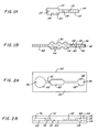
- Figures 1A and 1B are plan views of two embodiments of the subject invention, Fig. 1A employing a single capillary and chamber and Fig. 1B employing two capillaries separated by a chamber.
- Figures 2A and 2B are a plan view and a side elevational view of a device employing three chambers.
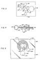
- Figure 3 is a plan view of a device for a plurality of simultaneous determinations.
- Figure 4 is a plan view of an alternate embodiment, where the sample is divided into two separate channels.
- Figure 5 is a plan view of an alternate embodiment employing an extended capillary path.
- Figure 6 is a cross-sectional view of an embodiment showing the location of channels and energy directing ridges during the fabrication process.
- Figure 7 is a block diagram of an electronic circuit suitable for use in an electronic capillary cartidge device to simulate the passage of blood through a capillary in a control cycle.
- Figure 8 is a diagram of the physical location and electronic circuitry of a detector capable of determining depletion of sample in a reservoir of a capillary device.
- This invention provides devices and methods, where the devices rely upon capillaries, chambers, and orifices to pump fluids; to control measurement of fluids, reaction times, and mixing of reagents; and to determine a detectable signal.
- the methods may involve the binding of homologous members of a specific binding pair, resulting in complex formation.
- the complex formation can provide for a variety of events which can be detected by instrumentation or visual means.
- the methods may involve chemical reactions, for example, the detection of glucose or serum enzymes, which result in a detectable change in the sample medium. Since the devices rely upon capillaries and other chambers to control movement of fluids, accurate control of the dimensions of the internal chambers is essential. The fabrication techniques described later provide this accurate control.
- the sample may be a fluid which is used directly as obtained from the source or may be pretreated in a variety of ways so as to modify its character.
- the sample will then be introduced into the device through an inlet port, which may introduce the sample into a chamber or a capillary.
- the sample will then transit the device passing through the capillary(ies) or chamber(s), where the sample will encounter one or more reagents, which reagents are involved in a system which produces a detectable signal.
- an inlet port which may introduce the sample into a chamber or a capillary.
- the sample will then transit the device passing through the capillary(ies) or chamber(s), where the sample will encounter one or more reagents, which reagents are involved in a system which produces a detectable signal.
- any liquid sample may be employed, where the sample will have a reasonable rate of flow due to the pumping of the capillary action. It is to be understood the capillary action is the sole driving force, relying on the surface action between the surface and the fluid. Where the sample is too viscous, it should be diluted to provide for a capillary pumping rate which allows for the desired manipulations, such as mixing, and for a reasonable flow time which will control the time period for the assay.
- the sample may be derived from any source, such as a physiological fluid, e.g., blood, saliva, ocular lens fluid, cerebral spinal fluid, pus, sweat, exudate, urine, milk.
- a physiological fluid e.g., blood, saliva, ocular lens fluid, cerebral spinal fluid, pus, sweat, exudate, urine, milk.
- the fluid may be subjected to prior treatment, such as preparing serum from blood, diluting pus, saliva; the methods of treatment may involve concentration, by filtration, distillation, dialysis, or the like; dilution, filtration, inactivation of natural components, concentration, chromatography, addition of reagents, chemical treatment.
- samples of interest include process streams, water, soil, plants or other vegetation, air.
- Analytes are widely varied depending upon the purpose of the assay and the source.
- Analytes may include small organic molecules, such as drugs, hormones, steroids, neurotransmitters, growth factors, commercial chemicals, degradation products, drugs of abuse, metabolites, catabolites.
- Large organic molecules may be determined, such as nucleic acids, proteins, polysaccharides.
- Aggregations of molecules may also be of interest, particularly naturally-occurring aggregations such as viroids, viruses, cells, both prokaryotic and eukaryotic, including unicellular microorganisms, mammalian cells such as lymphocytes, epithelial cells, neoplastic cells.
- Phenomena of interest which may be measured may be indicative of physiological or non-physiological processes, such as blood clotting, platelet aggregation, complement-mediated lysis, polymerization, agglutination.
- the sample medium may be the naturally-occurring medium or the sample introduced into a liquid meidum which provides for the desired characteristics necessary for the capillary pumping action and the detectable signal.
- aqueous media will be employed and to that extent aqueous media will be exemplary of the media employed in the subject invention.
- the aqueous media may be modified by the addition of a variety of miscible liquids, particularly oxygenated organic solvents, such as lower alkanols, dimethyl formamide, dimethyl sulfoxide, acetone. Usually, the solvents will be present in less than about 40 volume percent, more usually in less than about 20 volume percent.
- liquid or solid additives may be included in the medium to modify the flow or other properties of the medium, such as sugars, polyols, polymers, detergents, surfactants, involved with changes in wetting, adherence, laminar flow, viscosity.
- Buffers may be desirable to maintain a particular pH.
- Enzyme inhibitors may be included.
- Other reagents of interest are antibodies, preservatives, stabilizers, activators, enzyme substrates and cofactors, oxidants, reductants, etc.
- filtration or trapping devices may be included in the device pathway, so as to remove particles above a certain size.
- the particles may include cells, viruses, latex particles, high molecular weight polymers, nucleic acids, by themselves or in combination with proteins, e.g., nucleosomes, magnetic particles, ligand or receptor containing particles.
- the sample may provide the detectable component of the detection system or such component may be added.
- the component(s) will vary widely depending upon the nature of the detection system.
- One detection method will involve the use of particles, where particles provide for light scatter or a change in the rate of flow.
- the particles may be cells, polymeric particles which are immiscible with the liquid system, latex particles, charcoal particles, metal particles, polysaccharides or protein particles, ceramic particles, nucleic acid particles, agglutinated particles.
- the choice of particle will depend upon the ease of detection, the dispersability or stability of the dispersion, inertness, participation in the change in flow, and the like.
- Particle sizes will generally be from about 0.1-100 ⁇ , more usually from about 5-15 ⁇ .
- Other phenomena which may be detected include changes in color, light absorption or transmission, fluorescence, change in physical phase.
- the neat sample or formulated sample will be introduced into the entry port into the receiving unit of the device.
- the receiving unit may be a capillary or a chamber.
- the receiving unit may be used to measure the particular sample volume or may simply serve to receive the sample and direct the sample to the next unit of the device.
- the capillary units serve a variety of functions, including a measuring device for volume measurement, a metering pump for transferring liquid from one chamber to another, flow controller for controlling the rate of flow between chambers, mixer for mixing reagents, and detecting unit for detection.
- the capillaries will serve as transfer units, flow control units and detection units.
- the chambers and capillaries may be used to define different events, e.g., areas of reaction, or different structural entities in certain embodiments of the method.
- the capillaries will usually be of a substantially smaller cross-section or diameter in the direction transverse to the direction of flow than the chambers.
- the cross-section or length in the direction of flow may be similar or may differ by a factor of ten or more depending on the function of the capillary and the chamber.
- Capillaries will usually have diameters in the range of about 0.01mm to 2mm, usually about 0.1mm to 1mm.
- the length of the capillary, particularly the first capillary in the pathway, more particularly the first capillary when it is joined to the entry port, will be at least about 3mm, more usually at least about 5mm, and may be 1cm or more, usually not more than about 2cm, while subsequent capillaries may be shorter or longer, frequently at least one being longer, being as long as 10cm, usually not exceeding about 5cm.
- the first capillary will initially control the rate of flow into the chamber which will usually serve as the reaction chamber.
- the capillary may aid in the control of the time with which the assay medium is in contact with reagent contained within or bound to the walls of the capillary and/or reaction chamber and the progress of the assay medium through the chamber.
- Other components which may affect the rate of flow in the chamber include baffles, walls or other impedimenta in the chamber, the geometry of the chamber, the reagent in the chamber and the nature of the surfaces in the capillary and chamber. Since in many instances the initial contacting of the assay medium and the reagent could affect the results, it is desirable that the contact be sufficiently slow that equilibrium can occur, as to dissolution, reaction.
- the capillary control and use of relatively thin heat conductive walls allows for rapid heat transfer and isothermal conditions, or alternatively, thick walls can provide for adiabatic conditions.
- the small volume of fluid in the chambers and capillaries permits for rapid heat exchange or efficient thermal insulation.
- the thin capillaries permit optical measurements, particularly based on transmission of light, with optically dense samples, e.g., whole blood. There is the further opportunity for rapid efficient mixing, where by sonication the whole sample can be uniformly mixed.
- the capillary provides the sole driving source for the movement of liquid through the device. Accordingly, careful fabrication of the capillary to exact dimensions is required.
- the device is normally employed in the horizontal position, so that gravity does not affect the flow rate.
- the composition of the walls of the capillary are selected so as to provide the desired degree of wetting and surface tension or the walls are modified to provide the desired physical properties.
- the device is employed without ancillary motive force, such as pumps, gravity.
- the chambers also have a variety of functions, serving as protection for the reagent(s) mixing chambers for dissolution of reagent and/or reaction with reagent, volume measurement, incubation and detection, where the detectable signal is other than a signal associated with flow.
- the chambers will be primarily employed for mixing, incubating and for holding of liquids.
- the length of the capillaries, their cross-sectional area, the volumes of the various chambers, and their length and shape, may be varied widely.
- One constraint on each of the capillaries is the necessity for their function providing capillary pumping action for flow. Therefore air leaks in the space surrounding the capillary (except for designed access ports) cannot be tolerated.
- the chambers will also provide for capillary action while the flow rate which will be affected by the nature of the capillary surface will be primarily determined by the capillary action of the capillaries.
- the reagents may be supplied within the device, where by mixing with the reagents occurs in the device.
- the reagents may be present either diffusively or non-diffusively bound to the surface of the device, that is, adhered, absorbed, adsorbed or covalently-linked, so that the reagent may become dissolved in the fluid or may remain fixed to the surface.
- the reagents are diffusively bound (non-covalently and weakly bound)
- a variety of situations can be accommodated. One situation is where the liquid front dissolves all of the reagent, so that the liquid front receives a high concentration of the reagent and most of the reaction occurs at the liquid front.
- a second situation would be with an excess of a reagent of limited solubility.
- the reagent may be present in the liquid medium at a substantially uniform concentration.
- a third situation is to have a deficiency of a reagent of limited solubility, so that only the early portion of the fluid will have a relatively constant reagent concentration.
- reagents While for the most part, the reagent will be present in one or more units of the device, reagents also can be mechanically introduced by various techniques. For example, by employing a septum, a syringe may be employed for introducing a reagent. Alternatively, one could have an orifice and use an eyedropper or other means for introducing liquid reagent into the unit. Usually, unless essential, these alternative techniques will be avoided.
- the reagent will vary depending upon the nature of the sample, the analyte, and the manner in which the detectable signal is generated.
- a chemical reaction will occur due either to the formation of covalent bonds, e.g., oxidation or reduction, hydrolysis, or non-covalent bonds, e.g., complex formation between ligand and receptor, including complex formation between nucleic acids.
- the same or different reagent may be present in the various units, so that successive reactions can occur or a reagent continually supplied into the moving medium.
- the chambers can be varied in size and purpose, providing the varying incubation times, varying reaction times, mixing of media from different capillaries. Any number of chambers may be employed, usually not exceeding six, more usually not exceeding about four, where the chambers may be in series or parallel.
- the size of the unit, either capillary or chamber can be particularly important, where the reagent is fixed, so that the residence time in contact with the reagent will be affected by the area of the reagent contacted by the assay medium.
- filtration or trapping devices e.g., mechanical or magnetic
- red cells can be removed from blood, various components of the sample may be removed, or by employing divergent channels, one channel can have particles removed and the particles retained in the other channel where the two results may be of interest.
- the first concept will involve a characteristic other than a change in flow rate. For the most part, this will involve the absorption, scatter or emission of light.
- a wide variety of protocols and reagents are available which provide for a change in the measured light, as a result of absorption, scatter or emission, in relation to the amount of analyte in the sample.
- Labels which may be employed include enzymes, in combination with substrates, cofactors or inhibitors, fluorescers, combinations of fluorescers and quenchers, dyes. In some instances a chemical reaction occurs as a result of the presence of the analyte or with the analyte, which provides a detectable signal. By employing appropriate protocols, the amount of absorption or emission of light in the detection unit can be directly related to the amount of analyte in the sample.
- Detection of a change in the rate of flow may be the signal which results from the reaction of the label or may be the result of a combination or a plurality of entities, which affect the rate of flow.
- the change in flow rate may be as a result of agglutination, polymerization, complex formation between high molecular weight compounds or aggregations.
- the measurement of light can be used to measure a change in the size population. This can be particularly useful for measurement of agglutination, clumping, clot formation or dissolution.
- a laser is able to distinguish particle size without a change in the flow rate. Small particles have a low frequency and a high amplitude; large particles (agglutinated particles) have a lower frequency (fewer total particles) and a higher amplitude (each particle is larger). Thus the change in particle size distribution may be detected by integrated noise employing known circuitry.
- the assay medium may have no particles (entities capable of scattering) or have particles, such as cells, latex beads, where the result of the reaction is to change the particle size distribution, including going from no particles to the formation of particles.
- particles e.g., blood clots
- the reaction reduce the size and number of particles, e.g., dissolve the blood clots.
- Protocols which may find use include those found in U.S. Patent Nos. 3,817,837; 3,839,153; 3,998,943; 3,935,074; 4,174,834; 4,233,402; 4,208,479; 4,235,869; 4,275,149; 4,287,300, whose relevant disclosure is incorporated herein by reference.
- a fluorescence measurement may be made, where one has a single capillary as the inlet, with the capillary coated with antibody to analyte.
- the sample is diluted with a buffered reagent containing a conjugate of analyte with fluorescer, whereby all of the fluorescent reagent will become bound in the capillary in the absence of any analyte in the sample.
- the capillary is then introduced into the sample and an amount of liquid withdrawn up to an indexed point on the capillary, whereby the capillary is then withdrawn from the sample and the liquid allowed to progress into the chamber.
- the fluorescence off the chamber may then be read as indicative of the amount of analyte in the sample.
- a simple two-unit device employing a capillary and chamber, one could provide for using a combination of enzymes, referred to as channeling, where the product of one enzyme is the substrate of the other enzyme.
- channeling a combination of enzymes, referred to as channeling, where the product of one enzyme is the substrate of the other enzyme.
- the first unit mixes the sample with the enzyme inhibitor conjugate avoiding the necessity to combine the sample with a liquid medium.
- the sample is colored, such as blood, it may be necessary to filter out or trap red blood cells, to allow for development of color or fluorescence or to find a wavelength range, where one can read the development of a particular light-absorbing material.
- the enzyme-analyte conjugate in a first unit followed by antibody to anlayte in a second unit and employing a third unit containing enzyme substrate as the reaction chamber, the measurement can be made in the third unit.
- a second unit may then contain the particles containing antibody to the analyte.
- the amount of enzyme-analyte conjugate which binds to the antibodies will be dependent upon the amount of analyte in the sample.
- the third unit may then contain the enzyme substrate, so that reaction of the enzyme with the substrate can be monitored.
- clotting For the detection of change in flow rate, a wide variety of systems may be employed. Of particular interest is the natural system involving clotting, which is convenient when the sample is a blood sample. Thus, by adding one or more components of the clotting cascade or a component which activates the naturally-occuring components present, the clotting can provide for a change in the flow rate. Particularly, these reagents may include thromboplastin, factors I, II, IV, V, VII, VIII, IX, X, XI and XII. These components can be added individually or in combination.
- the clotting assay can be used to determine a wide variety of analytes of interest.
- the clotting assay may be used for the detection of the presence of anti-clotting agents or clotting agents.
- the clotting assay can be used for the detection of the level of a particular component required for clotting or a componenet involved in the dissolving of clots.
- Illustrative analytes include the various factors indicated above, warfarin, tissue plasminogen activator, heparin, streptokinase, Vitamin K, anti-platelet drugs, protamine sulfate.
- the clotting assay can also be used to measure any analyte of interest by having the analyte associated with a factor necessary for clotting. For example, by conjugating thromboplastin to a compound capable of competing with the analyte for a receptor, where the thromboplastin-receptor complex is inactive, one could determine the presence of the analyte.
- the sample would be mixed with the receptor for the analyte so that the binding sites of the receptor would be occupied by any analyte present.
- the thromboplastin conjugated to the analyte or mimetic analog would be the reagent in the reaction chamber.
- All the other components necessary for clotting would be included in the sample along with the antibodies for the analyte, where such other components were not naturally present in sufficient amount in the sample.
- the receptor sites which were not occupied by analyte would bind to the analyte conjugated to the thromboplastin where the resulting specific binding complex would lack thromboplastin activity.
- the remaining uncomplexed thromboplastin conjugate would be active and initiate clotting.
- particles will usually be included in the medium which become cross-linked in relation to the amount of analyte present.
- This can be achived by employing receptors and ligands specific for the receptor so that non-covalent binding provides for multiple linkages between particles with a resulting cross-link structure which can serve as a plug.
- S . aureus which specifically binds to immune complexes, red blood cells, synthetic or naturally-occurring particles to which ligands, rheumatoid factor, antibodies, naturally-occurring receptors, are conjugated
- the cross-linking of the particles can be retarded or enhanced by the presence or absence of the analyte.
- the antigen may serve as a bridge between different antibodies, while in the case of haptens, individual haptens may inhibit the cross-linking resulting from a polyhaptenic molecule.
- the reagents could include an agarose bead to which is bound polyclonal antibodies to an antigen of interest or monoclonal antibodies where different particles are specific for different epitopic sites of the antigen.
- the sample need only include the detection component and any of the analyte which may be present.
- the sample would mix with the antibody-conjugated particles in the reaction unit and then flow into the exit unit.
- the presence of the analyte would result in cross-linking of the particles with large amorphous particles providing a greater drag on flow smaller particles. As the accretion of particles increased, ultimately a plug would form and flow would stop.
- the sample could be combined with antibodies to the haptens.
- the reagent could be hapten conjugated to Porglas beads. Available antibody would be capable of cross-linking the hapten-conjugated beads so as to ultimately provide a plug which would inhibit further flow.
- Similar techniques could be used with hemagglutination where the particle is a red blood cell to which particular antigens are or have been bound.
- a sample which might contain cells having as part of their surface membrane the same antigen would be combined with the antigen conjugated red blood cell particles.
- the reagent would be antibody to the antigen.
- the rate of formation of the plug would vary depending upon whether cells containing the same antigen were present or absent.
- a further illustration would involve polymers to which are attached polyclonal antibodies, where the polymers are selected so as to have only moderate solubility in the assay medium. Binding to antigenic bridges would result in desolubilization.
- the polymers could be conjugated with nucleic acid sequences complementary to preselected sequences.
- the sequences would not be complementary to the nucleotide sequence of interest or to each other.
- the sample could be a lysate of a virus or pathogenic organism in an appropriate aqueous medium, where the genomic polynucleotides could be sheared.
- the sample would be combined with the polymeric reagents.
- the sample would then react in the reaction chamber with a nucleotide sequence which was a hybrid having a sequence complementary to the nucleic acid sequence of interest and a sequence complementary to the sequence bound to the polymer.
- the nucleic acid of interest would serve as a bridge to cross-link the polymeric molecules so as to set up a polymeric structure which would substantially slow the flow in the capillary and could, if desired, provide a plug.
- Another exemplification would employ dual receptors, e.g., antibody to analyte and antibody to a particle, such as an antigen of a red blood cell (RBC).
- dual receptors e.g., antibody to analyte and antibody to a particle, such as an antigen of a red blood cell (RBC).
- RBC red blood cell
- cross linking would occur between the antigen, dual receptor and RBCs to form large complexes modulating the flow rate, while in the absence of the antigen no complexes would be formed.
- the assay could be carried out by combining the sample with RBCs before introducing the sample into the device or by providing RBCs in the sample receiving chamber.
- the reaction chamber would have the dual receptor where complex formation would be initiated.
- the assay would be modified by employing a polyhapten reagent which could be added to the sample prior to introduction of the sample into the device.
- the presence of hapten would reduce complex formation in contrast to the result observed with the multivalent antigen analyte.
- Any system which results in a change in flow velocity or can be coupled to a reagent or system which affects flow velocity may be measured.
- Various systems have already been indicated which result in changes in flow rate.
- Other systems which could be coupled to compounds of interest are light initiated catalysis of polymerization, cellular aggregation initiated by lectin cross-linking, enzymatic reactions resulting in polymer initiation in conjunction with water-soluble monomers, e.g., hydroxyalkyl acrylates.
- the flow in the capillary channel unit can be detected by various techniques which allow for detection of fluid flow, e.g., flow sensors or pressure sensors, or by having a detectable component in the assay medium, which can be detected visually or by diode assay.
- Techniques which allow for fluid flow determinations include the use of means for measuring triboelectricity, means for detecting the rate of passage of liquid, detecting Doppler effects, or the like.
- a component is used in the medium which allows for flow detection by detecting the passage of the component through the first capillary channel exiting a receiving chamber.
- Flow can be detected by the creation of a speckle pattern resulting from the movement of particles in the first capillary channel and the passage of a coherent light source, e.g., laser beam, or an LED, through the channel.
- a coherent light source e.g., laser beam, or an LED
- a speckle pattern results from the interaction of particles and coherent light.
- Flow (motion) of the particles makes the speckels move with a frequency associated with the flow rate and the light or speckle fluctuations can be detected by a photodetector.
- the photodetector is designed to detect an area not greater than about the size of a speckle.
- a plurality of photodetector elements may be employed for detecting different areas and averaging the signals from each area.
- the speckle pattern can also be used to determine the size of the particles by analysis of the size of the speckles.
- the change in the light pattern as a result of a change in the rate of flow can be determined by appropriate electronic means, such as photodiodes or phototransistors, which would feed the electrical signal resulting from the fluctuating light to an appropriate circuit.
- appropriate electronic means such as photodiodes or phototransistors
- Particularly easy to distinguish is a flowing liquid from a stationary liquid.
- the slowing or stoppage of flow can be readily detected and the change in rate of flow or the time of passage through the first capillary can be determined from the beginning of flow to the stoppage of flow.
- capillary flow devices of the invention One possible problem that can occur in capillary flow devices of the invention is depletion of blood or another sample from the reservoir prior to the stoppage of flow caused by the detectable event being measured, such as coagulation.
- the detectable event such as coagulation.
- the liquid in the reservoir is drawn down so that essentially no more fluid is present in the reservoir, flow will stop since capillary forces will then be operating in both directions. Accordingly, it is useful to have a means of detecting this anomolous result in order to avoid a measurement of flow stoppage caused by this event being taken to represent the measurement flow stoppage.
- the actual device containing the capillary channels and other chambers is typically a flat cartridge that is inserted into an instrument which makes the various electronic measurements, detection of reservoir depletion can be accomplished by embedding various sensors into the electronic device that holds the reaction cartridge.
- measurement of depletion of fluid in the reservoir typically takes place in the presence of ambient light and other ambient conditions, variation in which must be accounted for in any measurement technique.
- One suitable measurement technique is to apply modulated light to the reservoir in a region adjacent to the capillary leading to the reaction chambers and other parts of the apparatus. In fluids containing particles, such as red blood cells in blood, light is scattered in all directions through the fluid even though the light is applied perpendicular to the reservoir. Some light will be scattered down the entry capillary, which will then act as a light guide.
- the capillary channel filled with blood can be considered to be a leaky waveguide for light, because a difference in refractive index between the blood (high refractive index) bounded by a low refractive index material (capillary channel) will provide light guidance, while the presence of red blood cells will scatter the light through the walls of the capillary channel, thereby providing the leaking effect. Since light will only be scattered in the presence of red blood cells or other particles, a detector located in close proximity to the channel will detect the scattered light.
- the modulation of the applied light will isolate the detector from ambient interferences. If the light is modulated at a defined frequency and detection electronics are sensitive only to that frequency, ambient effects will be eliminated.
- the modulation applied to the light can be of any type, such as sinusoidal waves or chopping, as long as the modulation can be both created and detected by electronic or mechanical means. Interferences from ambient light can further be eliminated by using infrared light, which offers additional advantages (when blood is the sample) of enhanced scattering and transmission.
- Detection of fluids in capillary channels is normally accomplished by measuring changes in absorption or transmission of light passed through the channel. However, in certain instances this will not be possible because of the physical restrictions on the reservoir and its location in the capillary device and the electronic apparatus into which the capillary device is inserted. For example, the size of a finger, if blood is being obtained from a finger stick, will require that the reservoir be separated sufficiently from the electronic device to allow the finger to be placed onto the reservoir. This will mean that both sides of the capillary device adjacent to the reservoir are not in contact with the electronic apparatus since at least one side must be accessible for the finger.
- the detector can be present either on the same side of the capillary on which light is applied, on the opposite side, or in any other physical relation as long as the detector is located adjacent to the channel.
- An additional useful control device is some means for simulating blood flow through a capillary channel in order to determine whether the electronic apparatus into which the cartridge is being inserted is fully operational. Numerous means of accomplishing this result are available, but one useful technique not believed to be previously used in any similar manner is described below.
- one useful technique for measuring blood flow is to detect the presence of the speckled pattern that results from the interaction of particles and coherent light. Any technique that simulates blood flow when such a detection system is being used will need to simulate the speckled pattern of light. Since the detector and the coherent light source are typically located in a close spatial relationship directly opposite each other so that insertion of the capillary device will result in light from the coherent light source passing directly through a channel in the device to the detector, simulation of blood flow requires insertion of some device into the electronic apparatus that can modulate the light beam.
- a useful technique is to include electronics and modulating devices directly in the capillary device so that each capillary cartridge can be used to determine the operating characteristics of the electronic apparatus containing the coherent light source and detector immediately prior to actual measurement being taken.
- this requires that the speckled pattern generator be such that it will not then interfere with the actual measurement.
- One means of accomplishing these results is to include a liquid crystal display-type apparatus at the location where measurement is being made. The liquid crystal material is selected so as to rotate polarized light that passes through it, the typical means by which liquid crystals operate.
- Polarizer filters will be present, either in the cartridge itself or in the electronic apparatus into which the cartridge is inserted that will result in the passage of light through the polarizing filters when the liquid crystal device is turned off. However, when the liquid crystal device is activated by application of a voltage, light passage will be blocked.
- the liquid crystal device when activated, it rotates the polarization of the laser beam, thereby reducing the passage of a light and generating light amplitude fluctuations, which are detected as being equivalent to the moving speckled pattern generated by passing coherent light through the thin film of particle-containing fluid that would normally flow down the capillary channel.
- a low viscosity liquid crystal material having a high refractive index change (thereby enabling rapid fluctuations) is desirable.
- a typical design uses a crystal oscillator and a chain of binary counters from which the liquid crystal display driver signals are derived as well as the time base for the measurements to be taken.
- the device will have at least one capillary channel unit, one chamber unit, an entry port, a vent, and a reagent bound to the surface.
- the device will be fabricated from materials with the appropriate physical properties, such as optical transmission, thermal conductivity, and mechanical properties, and which allow for uniform coating and stability of reagent, as well as medium compatibility, for example, blood compatibility. Where blood is the medium, the material should be configured to assure good blood flow stoppage or slowing once clotting is initiated.
- suitable plastics include those for high surface free energies and low water sorption, including PETG, polyester (Mylar R ), polycarbonate (Lexan R ), polyvinyl chloride, polystyrene, and SAN.
- a particularly preferred plastic is acrylonitrile-butadiene-styrene (ABS), particularly ABS supplied by Borg Warner under the tradename Cycolac.
- plastics are hydrophobic and exhibit poor reagent coating and poor blood flow
- the plastics can be rendered hydrophilic by treatment with argon plasma, using a plasma etcher or corona discharge. Suitable conditions are 10-25 watts at 13.56MHz and 133,3 Pa (one torr) chamber pressure for 5-10 min.
- a protein e.g., albumin coating
- Plasma etching and corona discharge provide markedly superior flow control characteristics and reproducibility.
- the device can be fabricated in a variety of ways.
- the receiving and reaction chambers can be formed in the plastic sheed by vacuum forming (PETG), injection molding (PETG, polystyrene, SAN), or hot stamping.
- Capillaries may be formed by etching a channel into the plastic.
- the device can be sealed by placing a cover slip (with appropriate vent holes at the inlet and vent) on the base sheet, and sealing with ultrasonic welding or by solvent bonding.
- cover slip with appropriate vent holes at the inlet and vent
- ultrasonic welding or by solvent bonding.
- markedly superior products are obtained by injection molding of the plastic device in pieces so as to form a depression in at least one surface of at least one plastic piece.
- ABS polymers are particularly suited to injection molding and additionally provide a clear plastic which is suitable for numerous optical detection techniques. ABS polymers are also suitable for ultrasonic welding.
- the chambers from two substantially flat plastic pieces in which the capillaries and other chambers are formed by producing matching depressions in two surfaces of two different shaped plastic pieces. It is preferred that on one of the pieces ridges, known as energy directors, completely surround the depression in a closely spaced relation so as to form a surface of first contact when the two pieces are placed together.
- the ridges are typically 0,1905 ⁇ 0.0127 mm (7.5 mil ⁇ 0.5 mil) above the surface of the plastic.
- the ridges are typically formed in the shape of a triangle, typically an equilateral triangle.
- the center of the ridge is typically 0,4445 ⁇ 0,0127 mm (17.5 ⁇ 0.5 mils) from the edge of the depression that will form the chamber.
- the pattern can be dye cut in a double-sided adhesive tape (e.g., 3M No. 666 tape, Fasson Fastape A) of appropriate thickness which is then sandwiched between a plastic base and cover slide.
- a double-sided adhesive tape e.g., 3M No. 666 tape, Fasson Fastape A
- the sandwiched layer may be die cut from a plastic piece of appropriate thickness which would be coated with adhesive and sandwiched in the same manner as the tape.
- the adhesive could also be silk-screened onto the base to give a raised pattern of desired thickness.
- the sheet thickness of the device in the region of the capillary channels will generally be equal to or exceed about 0,0508 mm (2 mil) to prevent compression due to the capillary action.
- each of the plastic layers comprising the top and bottom will be at least about 0,254 mm (10 mil) thick.
- the device will normally include a reagent within the reaction chamber.
- a reagent within the reaction chamber.
- it may be formulated neat or with various additives.
- the manner in which it is formulated, introduced into the reaction chamber and maintained in the reaction chamber, must provide for rapid mixing with the sample, reproducible distribution in the chamber, stability during storage, and reproducible reaction with the sample.
- the reagent may be sprayed, painted, introduced into the chamber as a liquid, lyophilized or evaporated, adsorbed, covalently conjugated.
- the active reagent may be combined with various stabilizers, excipients, buffers or other additives involved with the reaction.
- a small vial or other holder may be attached to the reaction unit, usually chamber, being stored as a liquid, where the liquid may be introduced into the reaction unit prior or concurrently with the sample entry into the reaction unit.
- a second receiving chamber may be employed connected to the reaction unit by a capillary channel, where transfer of the reagent in the second receiving chamber to the reaction unit is initiated in relation to introduction of the sample.
- the second receiving chamber could be filled and sealed, and then unsealed when the sample is introduced into the sample receiving unit.
- various mechanical or ultrasonic means may be employed to agitate the sample and reagents, where the mixing means may be internal or external.
- Vibrators, ultrasonic transducers, magnetic rods or other mechanical mixing means, flow disrupters, mixing baffles or barriers, flow directors, may be employed.
- the particular manner in which agitation is provided, if provided, will vary widely depending upon the degree of agitation needed, the design of the device.
- reagents can be used to ehance dissolution in a uniform manner.
- Such chemicals may include surfactants, polyols, sugars, emollients, liquids.
- the reagents may be formulated in a variety of ways to insure rapid and uniform mixing.
- heparin antagonists can be used to eliminate the effects of heparin on prothrombin time measurement.
- Typical heparin antagonists include protamine sulfate and polybrene.
- the reagent need not be coated or bound to the surface of the device, but may be provided as a soluble sponge or gel or alternatively, absorbed onto an insoluble sponge, membrane, paper (e.g., filter paper) or gel which is introduced into the reaction unit. In this manner the fluid may pass through the foam structure dissolving the reagent so as to form the reaction mixture.
- the reagent may be provided in liquid form in microcapsules.
- the liquid reagent could be released from the microcapsules by applying pressure to the walls of the reaction unit, resulting in breaking of the microcapsules and releasing the liquid reagent.
- the reagent need not be limited to a single reaction unit.
- the same or different reagents may be introduced into the capillary or in successive reaction units. In this manner a cascading reaction may be performed, where one is interested in allowing each reaction step of a sequence to proceed for a predetermined period before encountering the next reagent.
- Multiple reaction units also allow for the removal of components in the sample which may interfere with the desired reaction.
- one or more endogenous components bay be removed. Where particles are to be removed, filters may be employed at the entrance or exit to a reaction unit.
- micro-particles may be also included in the reaction unit which would be entrained with the moving front, where the microparticles could aid in the plug-forming mechanism for flow stoppage.
- a sample would be taken and treated as may be appropriate.
- Blood for example might be diluted and various reagents added, particularly where there is an interest in the determination of a particular clotting or anti-clotting factor.
- various particles might be added which had been functionalized by the addition of specific binding members, such as haptens, ligands, and receptors, particularly antibodies.
- specific binding members such as haptens, ligands, and receptors, particularly antibodies.
- the system may be devised where clotting will occur in the absence of the analyte.
- reagents will be added which, in the absence of the analyte, would be degraded in the reaction chamber.
- the sample medium would be introduced into the receiving unit and transferred by capillary action into the next unit. Either visual evaluation of the flow rate change or an electro-mechanical evaluation may be employed.
- the initiation of flow through the first capillary channel or through a successive capillary channel may be selected as the initiation time for measurement, or some point in between.
- various means may be employed for determining the flow velocity or time to flow stoppage.
- an apparatus comprising a semiconductor laser and photodectors may be employed.
- a photodetector of sufficiently small area By exposing a photodetector of sufficiently small area to a speckle pattern, a random signal (noise) is observed.
- the average of the random signal observed as a DC signal is inversely proportional to the red cell density, and changes in the fluctuation continues until flow stoppage, e.g., clotting, occurs.
- Such apparatus may include a housing for receiving and holding the device and means for controlling the temperature.
- the size of the area which is detected by an individual photodetector may be controlled in a variety of ways.
- One way, as indicated above, is to use a photodetector which has only a small photosensitive area, up to about the size of the speckle spot.
- Another way is to use an optical fiber. By controlling the parameters of the fiber, the area from which the fiber receives light may be controlled. Instead of a fiber, lenses may be employed to limit the observed area which lenses may be separate from or molded into the device.
- various spectrophotomers, fluorimeters, or the like may be employed for detection of the detectable signal.
- a single determination or multiple determinations may be made, based on a fixed value or a kinetic determination.
- FIG. 1A and 1B devices are depicted involving single chambers and one or two capillary units. These devices can be fabricated in a variety of ways, for example, having two sheets, where each of the sheets have been molded so as to define the particular units or one of the sheets defines the units and the other is a cover sheet, or having three sheets, where a sheet having cutouts defining the units is sandwiched between the other two sheets, where one or the other sheets provides the necessary orifices for the various ports. Other techniques may also be found to be useful for providing the chamber and channel cavities.
- capillary 12 is introduced into the sample, so that the inlet port 14 is completely submerged in the sample. It is important to avoid any air bubbles where the air bubbles could interfere with the measurement.
- the inner surface of the upper portion of capillary 12 is coated with reagent 16, so that as the liquid sample transits the capillary 12, the reagent 16 becomes dissolved in the sample.
- the capillary is removed from the sample, defining the sample volume, and the capillary inserted into a second fluid to maintain continuous flow. Otherwise, the sample drop can maintain a reservoir outside of the inlet port 14.
- the sample flows through capillary 12 into chamber 20 having vent 22.
- a second reagent 24 is coated onto the inner surface of reaction chamber 20, where the assay medium undergoes a second reaction.
- an assay medium could be prepared as the sample involving the fluid suspected of containing the analyte and a buffered mixture of enzyme-analyte conjugate.
- the reagent 16 would be antibody to the analyte, so that the enzyme-analyte conjugate present in the assay medium would become bound to the antibody in an amount related to the amount of analyte in the assay medium.
- the assay medium would then enter the chamber 20, where the reagent would be substrate for the enzyme.
- One can employ a substrate of limited solubility, so that the amount of substrate rapidly reaches equilibrium and remains constant during the measurment.
- One can also have a high concentration of a soluble substrate to maintain substrate concentration constant during the measurement.
- the rate can be monitored by the change in color or change in fluorescence over a predetermined time period.
- device 30 has capillary 32 which is divided into channels 34 and 36 containing reagents 38 and 40, respectively.
- the two channels share a common inlet port 42.
- Channel 34 contains reagent 38, referred to as the first channel and the first reagent, which could be microparticles to which are conjugated antibodies to a first epitope.
- Channel 36 and reagent 40 referred to as the second channel and the second reagent, would contain microparticles having monoclonal antibodies to a second epitope. In each case, the amount of monoclonal antibody would be substantial excess of any analyte which would be encountered.
- the analyte of interest would have a single epitope binding to the first reagent and a single epitope binding to the second reagent.
- the sample would travel through the channels at a substantially constant rate, with reaction occurring with any substance having the appropriate epitope.
- the particles conjugates would react with the particle conjugates and become bound to the particle conjugates.
- the particle conjugates would then exit channels 34 and 36 and enter incubation chamber 44.
- the chamber would also provide for capillary action, and agitation due to its accordian shape and vanes 46 for causing turbulence in the chamber 44.
- the microparticles would mix and cross link, if any analyte was present which had the two epitopes on the same molecule.
- the particles In the incubation chamber, the particles would have sufficient time to aggregate, so that upon entry into exit capillary 48, the particles which are formed would have a significant effect on the flow rate in capillary 48.
- the rate of flow or determining particle size or number of particles in capillary 48 one could determine the presence and amount of an analyte having both epitopes.
- the rate of flow or other parameter could be determined by the rate at which particles above a certain size transited a light path, using minimum light intensity fluctuations, level of scatter.
- the subject device illustrates the opportunity for having a plurality of capillaries to divide a sample into a plurality or portions, where each of the portions can be treated differently.
- the differently treated portions may then be brought together into a single chamber, where the different portions may interact in accordance with the desired protocol.
- the resulting assay medium may then be transferred to a capillary which may provide for measurement or way be further transferred to additional chambers for further modification.
- FIGS 2A and 2B are depicted a device having a plurality of chambers and allowing for interrupted flow.
- the device 50 is fabricated from three sheets, an upper sheet 52, a lower sheet 54, and a spacing sheet 56, which defines the various capillary units and chamber units.
- the device has three chambers, the receiving chamber 58, the reaction chamber 60, and the effluent chamber 62.
- Inlet port 64 receives the sample which is measured by filling chamber 58 and reaching the first capillary 66.
- Receiving chamber 58 is coated with first reagent 68, so that the sample undergoes a reaction in receiving chamber 58 and is modified.
- the modified sample then passes through capillary 66 and enters reaction chamber 60, which is coated with second reagent 70.
- the second reagent like the first reagent, is part of a detection system to provide for a detectable signal.
- Vent 72 is provided to stop the flow and allow for incubation in reaction chamber 60. This can be particularly useful where the slow step in the development of the detection system is complex formation. Depending upon the nature of the protocol, the period of incubation may be specifically timed incubation or may be one which is allowed to sit for a sufficient time to ensure completion and then the determination made.
- Effluent chamber 62 has exit vent 74 to permit flow past intermediate vent 72 when intermediate vent 72 is closed. Upon closing of intermediate vent 72, the assay medium will then flow through capillary 76 into effluent chamber 62. Instead of sealing the vent, other alternatives, such as applying pressure or centrifugal force, may be used to restart flow.
- the device is comprised of a block 78 which may be configured to be introduced into a instrument for assay determination.
- the various sheets will be constructed so as to ensure sufficient mechanical stability to withstand capillary action and provide for the necessary characteristics for flow of the assay medium and detection of the detectable signal.
- the subject device may be employed for flow stoppage, such as coagulation, where the coagulation may occur in the effluent chamber 62.
- flow stoppage such as coagulation
- the first chamber has bead conjugated ligands and the analyte of interest is a particular antibody.
- the sample would be introduced into the receiving chamber 58, where reaction would occur between the bead conjugated ligands and any antibody present in the sample.
- the sample would then flow to the reaction chamber 60, which would contain a reagent which binds specifically to antibody-ligand complexes, such as S . aureus protein A or rheumatoid factor, which binds specifically to poly(antibody-ligand) complexes.
- any bead conjugate which becomes bound to antibody would be removed from the liquid phase of the assay medium.
- the device 50 could then be inserted into an instrument, which would cover vent 72, allowing for flow through capillary 76.
- reagent 68 would be Fab fragments of monoclonal antibodies specific for the major histocompatibility antigen.
- the Fab fragments could be from murine or other non-human source of monoclonal antibodies.
- the reagent 70 would then be particles to which anti-murine immunoglobulin were conjugated. In this way, when the Fab-bound cells entered the reaction chamber 60, they would bind to the latex particle conjugates so as to form extended structures.
- the medium Upon closing of the vent 72 by introducing device 50 into an instrument, the medium would flow through capillary 76, where large particles could be determined by the scattering of light, or the pattern of transmission of light through the capillary and blockage by the cellular-particle aggregations.
- FIG. 3 is depicted a device which is exemplary of the determination of a plurality of anlaytes in a single sample.
- the device 80 has a receiving chamber 82 with inlet port 84.
- the sample would be introduced into the receiving chamber 82 and be pumped by capillary action through channel 86 into reaction chamber 88.
- reaction chamber 88 would be one or more reagents 108 which would provide part of the detection system.
- the assay medium would then be pumped by means of capillaries 90, 92 and 94 to chambers 96, 98 and 100, respectively.
- the media in chambers 96 and 98 would then be pumped by means of side capillaries 102 and 104 to final chamber 106. In this way, a variety of reactions could occur, where reagents could be provided in the various side chambers for further reaction allowing for detection of a plurality of epitopic sites.
- a lysate the serotype of a particular pathogen.
- the lysate would be introduced through inlet port 84 into the receiving chamber 82 and then be pumped into the reaction chamber 88.
- reagent 108 which would be monoclonal antibody-bead conjugates to a public epitope of the particular pathogen.
- each of the chambers 96, 98 and 100 would be monoclonal antibodies to an epitope specific for a particular serotype, where the antibodies are conjugated to larger beads which are distinguishable by light scattering properties from the beads in chamber 108. Thus, if the signal character changes in chambers 96, 98 or 100, this would be indicative of the particular serotype.
- Chamber 106 a narrow chamber susceptible to particle blockage, would have vent 110 to allow for flow into chamber 106.
- Capillaries 102 and 104 would pump the assay medium from chambers 96 and 98 into chamber 106, where the presence of the particular antigen would result in cross linking of the antigen. Cross-linking of the antigen would result in plug formation.
- the assay medium can be treated in multiple different ways and, if desired, rejoined in a single chamber as indicated above. This can be useful in situations where one is interested in different analytes, which may have different combinations of epitopes, or where the analyte must be treated in different ways in order to provide the detectable signal, or where one wished to add different combinations of labels to the analyte, where one wishes to provide a check on the results observed, or the like.
- FIG 4 is depicted a device which allows for the simultaneous determination of a sample background value and the detectable signal.
- the device 120 has an inlet port 122 separated by partition 124 which extends through capillary 126, chamber 128 and second capillary 130.
- Capillary 130 evacuates into effluent chamber 132 having vent 134.
- Chamber 128 is divided into two half chambers or semichambers 136 and 138.
- semichamber 136 two reagents are present indicated by the slanted lines and the crosses.
- the slanted lines are monoclonal antibodies specific for an epitope on the analyte, where the antibodies are non-diffusively bound to the surface.
- the crosses indicate monoclonal antibodies conjugated to fluorescers, where the monocolonal antibodies bind to a different epitope of the analyte.
- the fluorescer conjugate is reversibly bound to the surface of the two chambers 136 and 138 in the area near the entry ports 140 and 142 of capillary 126.
- the sample inlet port is submerged into the sample and the sample allowed to rise in the capillary 126. Sufficient sample is introduced and the two chambers 136 and 138 are filled.
- sample reaction chamber any analyte will become bound both to thee antibody bound to the surface and the fluorescer conjugate, so that the amount of fluorescer conjugate which remains in the sample reaction chamber 136 will be dependent upon the amount of analyte in the sample.
- sample which traverses control reaction chamber 138 will bind to the fluorescer conjugate but continue through the chamber into capillary 130.
- the capillary region 144 will be the region for determination of the amount of analyte, while the capillary region 146 will serve as the control.
- the amount of fluorescence observed in region 146 will be the maximum amount of fluorescence available from the combination of sample and fluorescer conjugate. Any reduction in fluorescence in the capillary region 144 will be as a direct result of the presence of analyte.
- the two streams will then exit into effluent chamber 132.
- the next embodiment 160 provides a serpentine path.
- the device has a housing 162 which is a rectangular plastic block shaped to fit into a reading apparatus (not shown).
- the block is indexed at site 164 for alignment to the apparatus.
- the receiving chamber 166 has a volume about one and one-half times the volume of the reaction chamber.
- the two chambers are connected by the first capillary channel 168.
- Inlet port 170 provides for introduction of the assay sample by syringe, eyedropper, or other convenient means.
- a serpentine capillary path 172 connects to outlet 174 of reaction chamber 176.
- the serpentine channel 172 terminates in reservoir chamber 178 which has outlet port 180.
- a "Y"-shaped device where one arm of the Y has a sample receiving chamber with the inlet port sealed.
- the sample receiving chamber is connected through a first conduit to the mixing member which serves as the trunk of the Y.
- the first conduit may be filled with a fluid which may be a buffer solution or other diluent.
- the second arm of the Y has a fluid chamber with a removalbe seal over a port.
- the fluid chamber is filled with a fluid which may serve as a diluent, reagent source, or the like.
- the fluid chamber may be as large as desired so that it may provide the desired ratio of fluid to sample.
- the fluid chamber is connected to the mixing member through a second conduit which is also filled with the fluid of the fluid chamber. The cross-sections of the first and second conduits are selected to provide for the proper volume ratio of the fluid and sample.
- the mixing member may be a capillary or chamber.
- the mixing member may be the final element of the device or may be connected to additional elements.
- the Y can serve as a complete device, by providing the mixing member with an outlet port or a part of a larger device by connecting the mixing member to additional capillaries and/or chambers.
- the seals are removed from the fluid chamber and sample chamber, while retaining the outlet port sealed to prevent flow.
- the inlet port may then be contacted with the sample and the outlet port unsealed.
- the sample and fluid from the two chambers will begin to flow and be mixed in the mixing member in the proper proportion.
- one can determine a number of different events by reading the flow of fluid in one of the capillaries.
- One application would be to provide fluorescent antibodies in the fluid chamber. Where the sample contains cells having the homologous ligand the mixing of the fluorescent antibodies and cells will result in large fluorescent particles as a result of the homologous antigen being present on the cells. These large fluorescent particles could then be detected by various means.
- Figure 6 shows a cross-sectional view through a section of a hypothetical device being prepared by ultrasonic welding from two injection-molded plastic pieces (not necessarily shown in any of the previous figures), prior to ultrasonic welding.
- the two plastic pieces 202 and 204 that will be used to form the internal chambers are shown properly aligned (i.e., in register) in Figure 6A.
- "Registration” is used here in the printing sense, referring to proper alignment of the depressions present in the surfaces of the two pieces that are used to form the internal chambers and capillaries. Proper registration can be aided by injection molding the two pieces to provide projections on one piece that fit into holes or depressions (other than capillary- or chamber- forming depressions) in the second piece.
- a single convoluted depression, 206 and 208, respectively, is formed into the surface of each piece, but the cross-sectional view shown in the figure cuts through the depression at three separate locations, two of which will result in capillary spaces (210 in Figure 6B) while the remaining location will result in the formation of a larger reaction chamber (212 in Figure 6B).
- Energy-directing ridges 214 can be seen in the surface of one of the two plastic pieces (204) adjacent to the periphery of the depression.
- Figure 6B shows the same cross-sectional view after ultrasonic welding.
- the plastic has melted selectively in the region of the energy-directing ridges so that the two plastic pieces have melted into each other to form a seal around the capillary and the reaction chamber.
- ultrasonic welding is carried out only until a seal is formed and does not need to be carried out until the entire plastic surfaces have welded together.
- Unwelded contact surfaces are shown by reference numbers 216 in Figure 6B.
- Use of energy ridges and short welding times also ensure that the dimensions of the depressions will be unaffected by the welding event. Welding time will be selected so that the melting (welding) almost but not quite reaches the edge of the depression. The extremely small cracks left between the two plates in the area of the capillaries will not adversely effect capillary action.
- Figure 7 shows electronic circuitry that can be utilized to simulate the passage of blood through a capillary flow device.
- the circuitry includes a crystal-controlled oscillator in which 220 represents the crystal and 222 represents the oscillator.
- the signal from the oscillator drives two frequency dividers (224 and 226) that will generate the output signals for a divider 228 of a liquid crystal display cell 230.
- Cell 230 is biased by an oscillating signal having a specific rate of oscillation, for example 128Hz. The cell will therefore rotate its polarization at the rate of 128Hz.
- Polarizer 231 in combination with cell 230 therefore operate to alternately block and pass light as a result of the rotating polarization.
- Two more dividers (232 and 234) drive a logical AND gate (236) whose output will go to a logic circuit low at defined intervals, for example, approximately every 20 seconds.
- a logical OR gate (238) will reset the dividers, thereby stopping the process. Accordingly, modulating signals for the liquid crystal display cell 230 are generated for the set time period, 20 seconds in the above example.
- the device is provided with a start switch 240. When switch 240 is closed, the reset signal is cleared, and the process is restarted.
- the oscillator, dividers, logic gates, and liquid crystal display driver can be implemented in CMOS technology using standard techniques of electronic fabrication.
- An CMOS device can be readily powered through more than 10,000 cycles when powered by a coin-type lithium battery.
- Figure 8 shows a device for determining when the sample present in a reservoir is depleted.
- blood is presumed to be the sample.
- Light source 246 is modulated by a modulator 248, typically a sinusoidal wave or square wave generator. A typical modulation frequency is about 8KHz. The modulated light will be scattered by red blood cells in the blood sample, and a fraction of this light will be guided by capillary channel 254 formed in the plastic capillary flow device 250.
- photodetector 252 typically located in close proximity to the inlet 254 of the capillary channel, will capture some of the scattered light.
- the signal output of the photodetector will consist of the superposition of ambient light and scattered light.
- the scattered light component is separated from the ambient light by a band-pass filter 256 and is further amplified by amplifer 258.
- This signal is rectified by rectifier 260 and integrated by integrater 262 in order to generate a direct current voltage proportional to the scattered light.
- Other types of signal generators can be used to produce a detectable signal that is seperable from ambient light and its possible variations.
- the term "filter” as used in this specification refers to any means of separating the detectable signal from variation in ambient light.
- the exact location of the ambient light source and detector in relation to the junction between the blood reservoir and the capillary can be varied depending on the capillary size, strength of a light source, detection limit of the detector, adsorbance of the sample, it is preferred that both the light source and the detector by relatively close to the junction, particularly when a highly abosrbant sample such as blood, it is utilized.
- an infrared light source it is preferred to place the light source from 0.5 to 2mm from the capillary entrance with an infrared-sensitive photodetector being located from 1 to 4mm from the junction.
- the light path between light source 246 and photodetector 252 will be interrupted, thereby reducing the voltage output from integrator 262.
- a comparator 264 By connecting the output of the integration to a comparator 264, a logical level indicating the presence or absence of sample in the reservoir is obtained. Furthermore, by adjusting the position of the light source or the reference voltage of the comparator, the volume of sample in the reservoir at which the decision "no sample" is made can be controlled.
- An infrared light source is preferred because of its larger efficiency in converting electric current into light, as compared to visible-light light-emitting-diodes.
- a modulating frequency of several kilohertz (preferably 3 to 20 kHz) is selected in order the move the modulation frequency from the low 60Hz harmonics present in artificial illumination, thereby simplifying the separation of ambient light and signal light. The separation is enhanced even further by the selection of an infrared light source.
- the individual chambers and channels can be provided.
- the designs and channels will be selected to provide for optimum sensitivity for particular assays.
- the volumes of the chambers will be chosen so as to accommodate an appropriate sample volume.
- the nature and cross section of the first capillary channel together with the size of the reaction chamber will control the residence time of the assay medium in the reaction chamber.
- a reaction will terminate upon the sample exiting the reaction chamber, e.g., antigen-antibody complex formation, pro-enzyme to enzyme, etc., where a component is bound to the surface of the chamber.
- the reaction occurring in the reaction chamber may result in a product which produces a blockage in the second capillarly channel or prevents a blockage from forming.
- the residence time for the reaction in the reaction chamber can be carefully controlled by controlling the dimensions of the capillary channels and reaction chamber, as well as temperature.
- capillary channel any type of capillary channel may be employed which provides for accommodating the appropriate volume and time period to flow stoppage.
- Various designs may be used such as serpentine, linear, U-shaped, pleated, or the like.
- the channel cross-section may be circular, ellipsoid, rectangular, or combinations thereof.
- the length of the channels may be determined empirically depending upon the other parameters involved.
- the initial or metering channel may be of constant or varying cross-section.
- the observed flow velocity will diminish with the path length traversed. Therefore, the observed change in velocity will have two components: (1) an inherent reduction in velocity related to the increasing friction with increasing fluid path length; and (2) increasing or decreasing viscosity of the medium due to any reaction occurring.
- a tapered capillary may be employed.
- the taper can be calculated by determining the cross-section, e.g., height and width, of the channel for each point along the channel path.
- the equations below are employed. The equations are based on known principles of fluid mechanics (e.g., R. Byron Bird, Warren E. Stewart, Edwin N. Lightfoot, Transport Phenomena , John Wiley & Sons, Inc., 1960).
- the flowrate, Q, measured by the laser (in the first capillary channel) can be defined by: where, V is the velocity in the 2nd capillary, and A is the area of the 1st capillary channel, and:
- novel devices and methods are provided for measuring a wide variety of sample characteristics including analytes of interest.
- the devices provide for simple measurement or volumes, mixing of reagents, incubations, and visual or instrumental determination of the result.
- the detection system may involve the absorption or emission of light, or modulation of flow, including slowing, stoppage, or their reversal.
- Of particular interest is the use of blood where clotting can be determined or reagents affecting clotting.
- analytes which include naturally-occurring compounds or synthetic drugs.
- the devices allow for the simultaneous performance of controls and comparison of signals from the two media.
- channels and chambers may be employed, so that the pathways can diverge and converge, be broken up into a plurality of different pathways or a sample may be divided into a plurality of paths and treated in a variety of ways.
- the devices can be simple to fabricate and the serpentine paths readily devised by employing known fabrication techniques, with particularly advantageous devices being available through use of the preferred fabrication techniques described herein.
- a device or cartridge analogous to the device of Figure 5 is employed. Two pieces of cellulose acetate 0.2032 mm (40 mil) thick are separated by scored Fason fast tape B to provide the proper design of channels and chambers.
- the reaction chamber contains a thromboplastin reagent where an aqueous solution of the thromboplastin is introduced into the chamber, the water evaporated, leaving the chamber coated with thromboplastin.
- the thromboplastin reagent composition is: 15mg/ml rabbit brain thromboplastin extract; 1% glycine; 0.01% thimerosol; 0.01% streptomycin-sulfate; 0.01% triton X100 R ; 0.08% phenol; 1% polyethylene glycol 3500; 4% sucrose; 0.001% polybreneTM.
- the mixture is lyophilized and reconstituted to 0.25 original volume with deionized water. Three ⁇ l of the reconstituted liquid is then placed on the reagent area of the device and then allowed to air dry before attaching the other sheet or cover of the device. A cover is then placed over the chambers and channels, and a 15 ⁇ l blood sample is introduced into the receiving chamber.
- the device is then inserted into a monitor which may be thermostatted at 25°C or 37°C, where a gallium arsenide semiconductor laser of wavelength 0.78 ⁇ directs a beam at a site between the ends of the channel joining the receiving chamber and the reaction chamber.
- a gallium arsenide semiconductor laser of wavelength 0.78 ⁇ directs a beam at a site between the ends of the channel joining the receiving chamber and the reaction chamber.
- a silicon photodetector of a small area sufficient to detect the oscillating speckled pattern resulting from the red blood cells flowing through the channel.
- a DC signal is observed with large fluctuations.
- the DC signal is inversely proportional to the red cell density, and fluctuation continues until clotting occurs.
- the time is then related to known standards to determine the clotting characteristic of the blood.
- the time for clotting can be related to the effect of warfarin on the blood clotting time.
- the light absorbance in the channel can be determined to provide for a hematocrit, as a further characteristic of the blood sample. Because of the short path length of the light, undiluted blood can be used which provides a further convenience.
- the receiving chamber (166) is 0.467cm wide by 0.09cm deep.
- the first capillary channel (168) is 1.3mm wide by 0.09mm deep.
- the reagent chamber (176) is a elipse of major axis 12mm and minor axis 6mm and is 0.09mm deep.
- the serpentine capillary path (172) is 160mm long tapering from a radius of 0.09mm at the outlet or the reagent chamber to 0.185mm at the outlet port (180).
- An electronic cartridge capable of simulating the flow of whole blood through a capillary was prepared using a 32768Hz crystal-controlled oscillator to drive two 1-16th frequency dividers that generated the input signals for a driver of a liquid crystal display cell prepared in accordance with the electronic diagram set forth in Figure 7.
- This cell was biased by a 2048Hz signal modulated at 128Hz intervals. The cell therefore rotated its polarization at the rate of 128Hz.
- a start switch was provided to clear the reset signal and restart the process.
- the oscillators, dividers, logic gates, and LCD driver were implemented in CMOS technology and powered by a coin-type lithium battery.
- the electronic cartidge has a life of more than 10,000 cycles.
- the following sample depletion device was prepared in the manner shown in Figure 8.
- An infrared LED was embedded into the surface of the analytical device into which a capillary flow cartridge was to be inserted so that the output of its light would impinge upon the blood reservoir 1mm from the capillary entrance.
- the LED is powered by an operational amplifier configured as a square wave generator of about 8KHz.
- An infrared-sensitive photodetector was located 2mm from the junction of the sample reservoir and the capillary channel.
- the signal output of the detector was passed to a band-pass filter having a center at 8KHz and a bandwidth of 500Hz and was further amplified by an amplifier.
- the amplified signal was rectified and integrated, thereby generating a direct current voltage proportional to the scattered light.
- Plastic cartridges were injection molded out of Cycolac R CTB Resin (acrylanitrile-butadiene-styrene copolymer) obtained from Borg-Warner Chemicals, Inc.
- Cycolac R CTB Resin acrylanitrile-butadiene-styrene copolymer obtained from Borg-Warner Chemicals, Inc.
- the design of the cartridge capillary channel and overall structure is similar to that shown in Figure 5 in that it contains a sample reservoir, an initial short capillary, a reagent chamber and a second long capillary. However, the configuration of the actual chambers and capillaries differ from those shown.
- the cartridge consisted of a 0,762 mm (30-mil) base and a 0,762 mm (30-mil) cover.
- Both the cover and base were plasma etched in an LFE Model 1002 Plasma system with the following settings: argon pressure, 266,6 Pa (2 torr); argon flow, 1-3; forward RF powere, 100; etch time, 20 minutes.
- Three microliters of Biotrack thromboplastin reagent were then applied to the base of the oval area at the base of the cartridge and allowed to dry for 10 minutes in an environment kept at 25°C and 10% relative humidity.
- the etched cover was then placed on the base and welded thereto using a Branson 8400Z ultrasonic welder with the following settings: down speed, 3 seconds; hold time, 0.5 seconds; weld energy, 0.5Kjoule; and weld time, 0.26-0.30 second.
Landscapes
- Chemical & Material Sciences (AREA)
- Health & Medical Sciences (AREA)
- Engineering & Computer Science (AREA)
- Chemical Kinetics & Catalysis (AREA)
- Life Sciences & Earth Sciences (AREA)
- Dispersion Chemistry (AREA)
- Mechanical Engineering (AREA)
- Analytical Chemistry (AREA)
- General Health & Medical Sciences (AREA)
- Hematology (AREA)
- Physics & Mathematics (AREA)
- Biomedical Technology (AREA)
- General Physics & Mathematics (AREA)
- Clinical Laboratory Science (AREA)
- Biochemistry (AREA)
- Immunology (AREA)
- Pathology (AREA)
- Biophysics (AREA)
- Ecology (AREA)
- Plasma & Fusion (AREA)
- Molecular Biology (AREA)
- Urology & Nephrology (AREA)
- Food Science & Technology (AREA)
- Medicinal Chemistry (AREA)
- Investigating Or Analysing Biological Materials (AREA)
- Investigating Or Analysing Materials By Optical Means (AREA)
- Automatic Analysis And Handling Materials Therefor (AREA)
- Investigating Or Analyzing Non-Biological Materials By The Use Of Chemical Means (AREA)
Claims (37)
- Méthode pour déterminer la présence d'une quantité d'un produit à analyser dans un échantillon de fluide, ou une propriété de cet échantillon de fluide, qui consiste à :
appliquer ledit échantillon à un dispositif (10) comprenant un orifice d'entrée (14) pour ledit échantillon, une lumière (22), un parcours capillaire contenant une chambre (12, 20) reliant ledit orifice d'entrée (14) à ladite lumière (22) et un réactif (16, 24) dans ledit parcours capillaire (12, 20), méthode dans laquelle ledit échantillon s'écoule par ledit parcours (12, 20) sous l'action des forces capillaires, une interaction dudit réactif (16, 24) avec ledit échantillon modifiant la viscosité dudit échantillon ou une caractéristique dudit échantillon associée audit écoulement ;
à permettre audit échantillon d' interagir avec ledit réactif (16, 24) et de traverser au moins une partie dudit parcours capillaire (12, 20) ;
à détecter ladite viscosité ou caractéristique d'écoulement ; et
à relier ladite viscosité ou caractéristique d'écoulement à la présence ou à la quantité dudit produit à analyser dans ledit échantillon de fluide, ou à ladite propriété dudit échantillon . - Méthode selon la revendication 1, dans laquelle , soit ledit échantillon, soit ledit réactif (16,24) comprend des particules , ladite caractéristique d'écoulement implique un passage de ces particules à travers ledit parcours capillaire (12,20).
- Méthode selon la revendication 1 ou 2, dans laquelle ladite caractéristique d'écoulement comprend une modification de la distribution en taille des particules.
- Méthode selon l'une quelconque des revendications 1 à 3, dans laquelle ladite modification dans la distribution de la taille des particules provient de l'agglutination de ces particules.
- Méthode selon l'une quelconque des revendications 1 à 4, dans laquelle les globules rouges d'un échantillon de sang entier fonctionnent comme des particules dans ledit parcours capillaire (12, 20) et ladite caractéristique d'écoulement comprenant l'interruption d'un faisceau lumineux dirigé à travers ledit parcours capillaire (12, 20) par lesdits globules rouges, lorsque ces globules passent à travers le parcours (12, 20).
- Méthode selon l'une quelconque des revendications 1 à 5, dans laquelle des particules sont présentes dans ledit échantillon.
- Méthode selon l'une quelconque des revendications 1 à 5, dans laquelle des particules sont présentes dans ledit réactif (16, 24).
- Méthode selon l'une quelconque des revendications 1 à 7, dans laquelle ladite caractéristique d'écoulement comprend une modification de la vitesse de passage des particules dans ledit parcours (12,20).
- Méthode selon l'une quelconque des revendications 1 à 7, dans laquelle ladite caractéristique d'écoulement est une modification de la vitesse d'écoulement de l'échantillon à travers ledit parcours capillaire (12, 20).
- Méthode selon l'une quelconque des revendications 1 à 9, dans laquelle ledit échantillon est constitué de sang entier.
- Méthode selon l'une quelconque des revendications 1 à 10, dans laquelle ladite modification d'écoulement consiste en un ralentissement ou un arrêt de l'écoulement, suite à la formation d'un caillot.
- Méthode selon l'une quelconque des revendications 1 à 10, dans laquelle ladite modification d'écoulement est le démarrage de l'écoulement suite à la dissolution d'un caillot.
- Méthode selon la revendication 1, dans laquelle ledit échantillon comprend du sang entier, ledit réactif (16,24) initiant une coagulation dudit échantillon.
- Méthode selon la revendication 1, dans laquelle ledit parcours capillaire (12, 20) comprend au moins une chambre (20) contenant ledit réactif (24) et au moins une unité capillaire (12), ayant une surface de section transversale inférieure à la surface de section transversale de la chambre (20).
- Méthode selon la revendication 14, dans laquelle ledit parcours capillaire comprend ledit orifice d'entrée, une unité de chambre, une première unité capillaire reliant ledit orifice d'entrée à ladite unité de chambre, une lumière, et une seconde unité capillaire reliant ladite unité de chambre à ladite lumière, dans laquelle un échantillon appliqué audit orifice d'entrée est transporté par ledit premier capillaire à ladite unité de chambre et est transporté par ladite seconde unité capillaire de ladite unité unité de chambre vers ladite lumière.
- Méthode selon la revendication 15, dans laquelle ledit dispositif comporte un troisième orifice, proche d'une liaison de ladite chambre avec ladite seconde unité capillaire, dans laquelle la transmission dudit échantillon s'achève au niveau du troisième orifice pour permettre une incubation dudit échantillon avec ledit réactif, ladite méthode comprenant , de plus, une étape de fermeture étanche dudit troisième orifice après ladite incubation pour permettre un mouvement continu dudit échantillon de ladite unité de chambre vers ladite seconde unité capillaire.
- Méthode selon la revendication 1, dans laquelle plus d'un parcours capillaire reçoit un échantillon issu d'un seul orifice d'entrée.
- Méthode selon la revendication 17, dans laquelle chacun desdits parcours capillaires contient un réactif différent.
- Dispositif de contrôle capable de détecter la déplétion d'un fluide contenant des particules dans un dispositif selon la revendication 1 contenant un réservoir d'échantillon (242), ledit parcours capillaire (254) sortant dudit réservoir (242), lequel comprend :
une source lumineuse (246), disposée de façon à être captée par ledit fluide dans ledit réservoir (242) ;
un détecteur de lumière (252), disposé tout près dudit parcours capillaire (254) de façon à recueillir la lumière qui est réfléchie par lesdites particules dans ledit parcours capillaire (254) et ensuite réfléchie ,de plus, par lesdites particules, de façon à traverser les parois dudit parcours capillaire (254) ;
un générateur de signaux (248), fixé de façon opérationnelle à ladite source lumineuse (246), dans lequel un signal détectable est imposé à la sortie de ladite source lumineuse ; et
un filtre (256), fixé de façon opérationnelle à la sortie dudit détecteur de lumière (252) , dans lequel ledit signal détectable est isolé des autres sources lumineuses qui peuvent être captées par ledit détecteur de lumière (252). - Dispositif de contrôle selon la revendication 19, dans lequel ladite source lumineuse (246) produit une lumière infrarouge et ledit signal détectable est une variation périodique de l'intensité de ladite lumière .
- Dispositif de contrôle selon la revendication 19, dans lequel une lumière issue de ladite source lumineuse (246) rencontre ledit fluide dans ledit réservoir (242), perpendiculairement à la ligne formée par ledit parcours capillaire (254).
- Dispositif de contrôle selon la revendication 19, dans lequel ladite source lumineuse (246) est une source de lumière infrarouge , ledit parcours capillaire (254) étant relié audit réservoir (242) au niveau de l'entrée du capillaire, ladite source lumineuse (246) étant située à une distance de 0,5 à 2mm de ladite entrée du capillaire, et ledit détecteur de lumière (252) étant placé à distance de 1 à 4 mm de ladite entrée du capillaire.
- Dispositif de contrôle selon la revendication 19, dans lequel une lumière issue de ladite source lumineuse (246) pénétrant dans ledit réservoir d'échantillon (242), est réfléchie essentiellement perpendiculairement à partir de ladite source lumineuse (246) dans ledit parcours capillaire (254) et sort dudit parcours capillaire (254) essentiellement perpendiculairement, pour être captée par ledit détecteur (252).
- Dispositif d'analyse pour détecter la présence d'un produit à analyser dans un échantillon de fluide physiologique , comprenant :
une enceinte (162), contenant un orifice d'admission (170), une unité de chambre (176), un orifice de sortie (180), une première unité capillaire (168) pour pomper de façon indépendante un liquide venant dudit orifice d'admission (170) vers l'unité de chambre (176), et une seconde unité capillaire (172) positionnée entre et raccordée directement à ladite unité de chambre (176) et audit orifice de sortie (180) pour pomper de façon indépendante un liquide venant de ladite unité de chambre (176) vers ledit orifice de sortie (180) ; dans lequel ledit orifice d'admission (170), la première unité capillaire (168), l'unité de chambre (176), la seconde unité capillaire (172), l'orifice de sortie (180) sont situés sur un parcours capillaire continu ; ladite enceinte (162) contenant de plus un réactif dans ledit parcours capillaire comprenant un élément choisi dans le groupe constitué de composés provoquant une coagulation du sang et des anticorps capables d'entrainer une modification dans la vitesse de l'écoulement dudit échantillon de fluide dans ledit parcours. - Dispositif selon la revendication 24, dans lequel ledit réactif comprend un anticorps.
- Dispositif selon la revendication 24, dans lequel ledit dispositif comprend au moins deux unités de chambre dans ledit parcours.
- Dispositif selon la revendication 24, comprenant de plus un orifice pouvant être étanche dans ledit parcours capillaire, proche d'une jonction entre l'unité de chambre et une unité capillaire.
- Dispositif selon la revendication 24, comprenant de plus, une troisième unité capillaire, pratiquement en parallèle avec ladite première unité et dirigeant le fluide dans ladite unité de chambre.
- Dispositif selon la revendication 24, dans lequel ledit réactif comprend un élément choisi dans un groupe consistant en composants de cascades de coagulations sanguines naturelles et de réactifs activant un composant d'une cascade de coagulation naturelle.
- Dispositif selon la revendication 24 ou 29, dans lequel ledit réactif est la thromboplastine.
- Dispositif selon la revendication 24, dans lequel ladite enceinte comprend un matériau pratiquement hydrophobe, ayant au moins une partie des parois dudit parcours capillaire traitée pour fournir une capacité hydrophile.
- Dispositif selon la revendication 24 ou 31, dans lequel ledit matériau est un plastique.
- Dispositif selon la revendication 24, fabriqué à partir d'au moins deux plaques de plastique pratiquement hydrophobe, dont l'une au moins est moulée pour fournir des dépressions pour la formation desdites unités de chambre et des capillaires, lesdites dépressions étant traitées pour présenter une capacité hydrophile, dans lequel au moins une plaque comporte des moyens définissant un passage formant ledit orifice d'admission ou ledit orifice de sortie, lesdites unités de chambre et les capillaires étant formés par la jonction desdites plaques pour constituer ladite enceinte.
- Dispositif selon la revendication 24 ou 33, dans lequel ladite unité de chambre contient ledit réactif et en ce que ledit réactif comprend un élément choisi dans le groupe constitué de composants des cascades de coagulations naturelles et de réactifs activant un composant d'une cascade de coagulation naturelle.
- Dispositif selon l'une quelconque des revendications 24, 33 ou 34, dans lequel ledit réactif comprend de la thromboplastine, dans ladite unité de chambre.
- Dispositif à utiliser dans un système de détection de la présence d'un produit à analyser dans un échantillon sanguin, comprenant :
un dispositif selon la revendication 1, dans lequel ledit parcours capillaire comprend une enceinte pratiquement hydrophobe, comportant une partie au moins de ses parois traitée pour avoir des capacités hydrophiles, et étant capable de pomper du sang comme unique source mobile dudit dispositif ; et
un réactif dans ledit parcours, dans lequel ledit réactif entraine le sang à coaguler et est un élément d'un système capable de fournir un signal détectable en relation avec la présence dudit produit à analyser ou de ladite propriété . - Dispositif selon l'une quelconque des revendications 24 à 36, caractérisé en ce que le réactif est fixé aux parois dudit parcours capillaire.
Priority Applications (4)
| Application Number | Priority Date | Filing Date | Title |
|---|---|---|---|
| AT8686110184T ATE105084T1 (de) | 1985-08-05 | 1986-07-24 | Kapillardurchflussgeraet. |
| EP19920101907 EP0483117B1 (fr) | 1985-08-05 | 1986-07-24 | Dispositif d'écoulement capillaire |
| EP19920103110 EP0488994B1 (fr) | 1985-08-05 | 1986-07-24 | Dispositif d'cÔntrole de qualité pour utilisation dans un instrument d'analyse |
| EP19920102342 EP0485368B1 (fr) | 1985-08-05 | 1986-07-24 | Dispositif d'écoulement capillaire |
Applications Claiming Priority (4)
| Application Number | Priority Date | Filing Date | Title |
|---|---|---|---|
| US76274885A | 1985-08-05 | 1985-08-05 | |
| US762748 | 1985-08-05 | ||
| US06/880,793 US4756884A (en) | 1985-08-05 | 1986-07-01 | Capillary flow device |
| US880793 | 1986-07-01 |
Related Child Applications (3)
| Application Number | Title | Priority Date | Filing Date |
|---|---|---|---|
| EP92101907.1 Division-Into | 1992-02-05 | ||
| EP92102342.0 Division-Into | 1992-02-12 | ||
| EP92103110.0 Division-Into | 1992-02-25 |
Publications (3)
| Publication Number | Publication Date |
|---|---|
| EP0212314A2 EP0212314A2 (fr) | 1987-03-04 |
| EP0212314A3 EP0212314A3 (en) | 1989-07-19 |
| EP0212314B1 true EP0212314B1 (fr) | 1994-04-27 |
Family
ID=27117182
Family Applications (4)
| Application Number | Title | Priority Date | Filing Date |
|---|---|---|---|
| EP19920103110 Expired - Lifetime EP0488994B1 (fr) | 1985-08-05 | 1986-07-24 | Dispositif d'cÔntrole de qualité pour utilisation dans un instrument d'analyse |
| EP19920102342 Expired - Lifetime EP0485368B1 (fr) | 1985-08-05 | 1986-07-24 | Dispositif d'écoulement capillaire |
| EP19920101907 Expired - Lifetime EP0483117B1 (fr) | 1985-08-05 | 1986-07-24 | Dispositif d'écoulement capillaire |
| EP19860110184 Expired - Lifetime EP0212314B1 (fr) | 1985-08-05 | 1986-07-24 | Dispositif d'écoulement capillaire |
Family Applications Before (3)
| Application Number | Title | Priority Date | Filing Date |
|---|---|---|---|
| EP19920103110 Expired - Lifetime EP0488994B1 (fr) | 1985-08-05 | 1986-07-24 | Dispositif d'cÔntrole de qualité pour utilisation dans un instrument d'analyse |
| EP19920102342 Expired - Lifetime EP0485368B1 (fr) | 1985-08-05 | 1986-07-24 | Dispositif d'écoulement capillaire |
| EP19920101907 Expired - Lifetime EP0483117B1 (fr) | 1985-08-05 | 1986-07-24 | Dispositif d'écoulement capillaire |
Country Status (6)
| Country | Link |
|---|---|
| US (1) | US4756884A (fr) |
| EP (4) | EP0488994B1 (fr) |
| JP (5) | JPH0658373B2 (fr) |
| AU (1) | AU593001B2 (fr) |
| CA (1) | CA1275231C (fr) |
| DE (4) | DE3689812T2 (fr) |
Cited By (7)
| Publication number | Priority date | Publication date | Assignee | Title |
|---|---|---|---|---|
| US6905882B2 (en) | 1992-05-21 | 2005-06-14 | Biosite, Inc. | Diagnostic devices and apparatus for the controlled movement of reagents without membranes |
| US7329496B2 (en) | 1990-12-06 | 2008-02-12 | Affymetrix, Inc. | Sequencing of surface immobilized polymers utilizing microflourescence detection |
| US7480032B2 (en) | 2001-11-08 | 2009-01-20 | Optiscan Biomedical Corporation | Device and method for in vitro determination of analyte concentrations within body fluids |
| US7524456B1 (en) | 1992-05-21 | 2009-04-28 | Biosite Incorporated | Diagnostic devices for the controlled movement of reagents without membranes |
| US8197770B2 (en) | 2005-02-14 | 2012-06-12 | Optiscan Biomedical Corporation | Fluid handling cassette having a spectroscopic sample cell |
| US8685715B2 (en) | 2004-10-28 | 2014-04-01 | Platform Diagnostics Limited | Agglutination reaction system |
| CN110461473A (zh) * | 2016-11-16 | 2019-11-15 | 奎多公司 | 全血分离的装置 |
Families Citing this family (461)
| Publication number | Priority date | Publication date | Assignee | Title |
|---|---|---|---|---|
| US4948961A (en) * | 1985-08-05 | 1990-08-14 | Biotrack, Inc. | Capillary flow device |
| US5144139A (en) * | 1985-08-05 | 1992-09-01 | Biotrack, Inc. | Capillary flow device |
| US5164598A (en) * | 1985-08-05 | 1992-11-17 | Biotrack | Capillary flow device |
| US5140161A (en) * | 1985-08-05 | 1992-08-18 | Biotrack | Capillary flow device |
| US4753776A (en) * | 1986-10-29 | 1988-06-28 | Biotrack, Inc. | Blood separation device comprising a filter and a capillary flow pathway exiting the filter |
| US4775515A (en) * | 1986-11-18 | 1988-10-04 | Cottingham Hugh V | Agglutinographic slide |
| DE3706718A1 (de) * | 1987-03-02 | 1988-09-15 | Boehringer Mannheim Gmbh | Vorrichtung zur durchfuehrung einer heterogenen reaktion |
| US4849340A (en) * | 1987-04-03 | 1989-07-18 | Cardiovascular Diagnostics, Inc. | Reaction system element and method for performing prothrombin time assay |
| US5110727A (en) * | 1987-04-03 | 1992-05-05 | Cardiovascular Diagnostics, Inc. | Method for performing coagulation assays accurately, rapidly and simply, using dry chemical reagents and paramagnetic particles |
| US5006464A (en) * | 1987-10-01 | 1991-04-09 | E-Y Laboratories, Inc. | Directed flow diagnostic device and method |
| DK163194C (da) * | 1988-12-22 | 1992-06-22 | Radiometer As | Fremgangsmaade ved fotometrisk in vitro bestemmelse af en blodgasparameter i en blodproeve |
| DE3889885T2 (de) * | 1987-12-23 | 1994-12-15 | Abbott Lab | Vorrichtung zur Agglutinierungsreaktion. |
| DE3814585A1 (de) * | 1988-04-29 | 1989-11-09 | Hoffmann La Roche | Testelement fuer agglutinationsuntersuchungen, verfahren zu seiner herstellung und dessen verwendung |
| US5096669A (en) * | 1988-09-15 | 1992-03-17 | I-Stat Corporation | Disposable sensing device for real time fluid analysis |
| US4952055A (en) * | 1988-10-03 | 1990-08-28 | Wyatt Technology Corporation | Differential refractometer |
| US5057279A (en) * | 1988-10-13 | 1991-10-15 | The United States Of America As Represented By The Secretary Of The Navy | Pressurized membrane chemical sensor |
| AU609332B2 (en) * | 1988-11-09 | 1991-04-26 | Biotrack, Inc. | Method and composition of stabilizing and solubilizing latex reagents |
| US5229297A (en) * | 1989-02-03 | 1993-07-20 | Eastman Kodak Company | Containment cuvette for PCR and method of use |
| US6645758B1 (en) | 1989-02-03 | 2003-11-11 | Johnson & Johnson Clinical Diagnostics, Inc. | Containment cuvette for PCR and method of use |
| IE940110L (en) * | 1989-03-23 | 1990-09-23 | Bunce Roger A | Liquid transfer devices |
| US5073216A (en) * | 1989-04-07 | 1991-12-17 | Abbott Laboratories | Method of ultrasonically cutting fibrous materials and device therefrom |
| US5104813A (en) * | 1989-04-13 | 1992-04-14 | Biotrack, Inc. | Dilution and mixing cartridge |
| AU5247790A (en) * | 1989-04-20 | 1990-10-25 | Biotrack, Inc. | Capillary flow device and reading instrument |
| US5039617A (en) * | 1989-04-20 | 1991-08-13 | Biotrack, Inc. | Capillary flow device and method for measuring activated partial thromboplastin time |
| US5286454A (en) * | 1989-04-26 | 1994-02-15 | Nilsson Sven Erik | Cuvette |
| SE465742B (sv) * | 1989-04-26 | 1991-10-21 | Migrata Uk Ltd | Kyvett foer upptagning foer minst ett fluidum |
| EP0397424A3 (fr) * | 1989-05-08 | 1991-08-21 | Biotrack, Inc. | Système d'analyse multiple |
| US5234813A (en) * | 1989-05-17 | 1993-08-10 | Actimed Laboratories, Inc. | Method and device for metering of fluid samples and detection of analytes therein |
| US5087556A (en) * | 1989-05-17 | 1992-02-11 | Actimed Laboratories, Inc. | Method for quantitative analysis of body fluid constituents |
| US5207988A (en) * | 1989-07-06 | 1993-05-04 | The Cleveland Clinic Foundation | Apparatus for detecting and quantifying clot lysis and establishing optimum medication and dosages |
| WO1991002589A1 (fr) * | 1989-08-18 | 1991-03-07 | Cambridge Bioscience Corporation | Appareil et procede de reaction employant un ecoulement gravitationnel |
| US5225163A (en) * | 1989-08-18 | 1993-07-06 | Angenics, Inc. | Reaction apparatus employing gravitational flow |
| US5030005A (en) * | 1989-11-29 | 1991-07-09 | Akzo N.V. | Liquid crystal device for calibration and testing of optical instruments |
| US5066465A (en) * | 1989-12-27 | 1991-11-19 | Olympus Optical Co., Ltd. | Reaction apparatus |
| US5188968A (en) * | 1989-12-28 | 1993-02-23 | Olympus Optical Co., Ltd. | Method and reaction kit for agglutination detection |
| US6176962B1 (en) | 1990-02-28 | 2001-01-23 | Aclara Biosciences, Inc. | Methods for fabricating enclosed microchannel structures |
| US5411894A (en) * | 1990-03-20 | 1995-05-02 | Abbott Laboratories | Method of using tissue and cell adhesive preparations for biological test systems |
| GB9009000D0 (en) * | 1990-04-21 | 1990-06-20 | Bovril Ltd | Novel process |
| WO1991018276A1 (fr) * | 1990-05-22 | 1991-11-28 | Kelly Kenneth A | Dispositif de microdosage a bandelettes pour dosage immunologique |
| TW221493B (fr) * | 1990-07-10 | 1994-03-01 | Cardiovascular Diagnostics Inc | |
| USD337164S (en) | 1990-07-19 | 1993-07-06 | I-Stat Corporation | Cartridge for a blood monitoring analyzer |
| US5124661A (en) * | 1990-07-23 | 1992-06-23 | I-Stat Corporation | Reusable test unit for simulating electrochemical sensor signals for quality assurance of portable blood analyzer instruments |
| US5208163A (en) * | 1990-08-06 | 1993-05-04 | Miles Inc. | Self-metering fluid analysis device |
| TW233341B (fr) * | 1990-08-23 | 1994-11-01 | Abbott Lab | |
| WO1992005440A1 (fr) * | 1990-09-26 | 1992-04-02 | Akers Research Corporation | Analyse de detection amelioree de ligands |
| CA2062027C (fr) * | 1991-03-04 | 1998-05-19 | William Aldrich | Systeme de controle du liquide pour cartouches de diagnostic utilisees dans des instruments d'analyse |
| CA2062338A1 (fr) * | 1991-03-15 | 1992-09-16 | Zia Yassinzadeh | Cartouche de commande electronique et methode de simulation de diagrammes de transmission lumineuse |
| US6007999A (en) * | 1991-07-31 | 1999-12-28 | Idexx Laboratories, Inc. | Reversible flow chromatographic binding assay |
| US5726010A (en) * | 1991-07-31 | 1998-03-10 | Idexx Laboratories, Inc. | Reversible flow chromatographic binding assay |
| US7297313B1 (en) | 1991-08-31 | 2007-11-20 | The Regents Of The University Of California | Microfabricated reactor, process for manufacturing the reactor, and method of amplification |
| US5540888A (en) * | 1991-11-11 | 1996-07-30 | British Technology Group Limited | Liquid transfer assay devices |
| US5222808A (en) * | 1992-04-10 | 1993-06-29 | Biotrack, Inc. | Capillary mixing device |
| US5430542A (en) * | 1992-04-10 | 1995-07-04 | Avox Systems, Inc. | Disposable optical cuvette |
| US5223219A (en) * | 1992-04-10 | 1993-06-29 | Biotrack, Inc. | Analytical cartridge and system for detecting analytes in liquid samples |
| US5580744A (en) * | 1992-04-27 | 1996-12-03 | Avocet Medical, Inc. | Test article and method for performing blood coagulation assays |
| DK0638127T3 (da) * | 1992-04-27 | 2000-12-18 | Avocet Medical Inc | Testartikel og fremgangsmåde til at udføre blodkoagulationsanalyser |
| CA2134474C (fr) * | 1992-05-01 | 1999-07-06 | The Trustees Of The University Of Pennsylvania | Dispositif microfabrique de manutention d'echantillons de sperme |
| US5637469A (en) * | 1992-05-01 | 1997-06-10 | Trustees Of The University Of Pennsylvania | Methods and apparatus for the detection of an analyte utilizing mesoscale flow systems |
| US6953676B1 (en) | 1992-05-01 | 2005-10-11 | Trustees Of The University Of Pennsylvania | Mesoscale polynucleotide amplification device and method |
| US5486335A (en) * | 1992-05-01 | 1996-01-23 | Trustees Of The University Of Pennsylvania | Analysis based on flow restriction |
| US5304487A (en) * | 1992-05-01 | 1994-04-19 | Trustees Of The University Of Pennsylvania | Fluid handling in mesoscale analytical devices |
| US5587128A (en) | 1992-05-01 | 1996-12-24 | The Trustees Of The University Of Pennsylvania | Mesoscale polynucleotide amplification devices |
| US5498392A (en) * | 1992-05-01 | 1996-03-12 | Trustees Of The University Of Pennsylvania | Mesoscale polynucleotide amplification device and method |
| US5726026A (en) * | 1992-05-01 | 1998-03-10 | Trustees Of The University Of Pennsylvania | Mesoscale sample preparation device and systems for determination and processing of analytes |
| US6767510B1 (en) | 1992-05-21 | 2004-07-27 | Biosite, Inc. | Diagnostic devices and apparatus for the controlled movement of reagents without membranes |
| US6156270A (en) | 1992-05-21 | 2000-12-05 | Biosite Diagnostics, Inc. | Diagnostic devices and apparatus for the controlled movement of reagents without membranes |
| US5458852A (en) * | 1992-05-21 | 1995-10-17 | Biosite Diagnostics, Inc. | Diagnostic devices for the controlled movement of reagents without membranes |
| US6019944A (en) * | 1992-05-21 | 2000-02-01 | Biosite Diagnostics, Inc. | Diagnostic devices and apparatus for the controlled movement of reagents without membranes |
| US5639423A (en) * | 1992-08-31 | 1997-06-17 | The Regents Of The University Of Calfornia | Microfabricated reactor |
| JPH08501392A (ja) * | 1992-09-14 | 1996-02-13 | パーデュー リサーチ ファウンデーション | 電気泳動法による化学分析 |
| US5500187A (en) * | 1992-12-08 | 1996-03-19 | Westinghouse Electric Corporation | Disposable optical agglutination assay device and method for use |
| US5302348A (en) * | 1992-12-10 | 1994-04-12 | Itc Corporation | Blood coagulation time test apparatus and method |
| DE69430679T2 (de) * | 1993-02-03 | 2002-12-19 | Histaggen Inc., Bowmanville | Verfahren zur Speicherung eines Liganden in einem freisetzbaren Behältnis und Verfahren zur Freisetzung eines Liganden daraus |
| US5670329A (en) * | 1993-05-28 | 1997-09-23 | Cardiovascular Diagnostics, Inc. | Method and analytical system for performing fibrinogen assays accurately, rapidly and simply using a rotating magnetic field |
| US5522255A (en) * | 1993-08-31 | 1996-06-04 | Boehringer Mannheim Corporation | Fluid dose, flow and coagulation sensor for medical instrument |
| US5526111A (en) * | 1993-08-31 | 1996-06-11 | Boehringer Mannheim Corporation | Method and apparatus for calculating a coagulation characteristic of a sample of blood a blood fraction or a control |
| US5841023A (en) * | 1993-08-31 | 1998-11-24 | Boehringer Mannheim Corporation | Magnet for medical instrument |
| EP0720439A4 (fr) * | 1993-08-31 | 1997-09-24 | Boehringer Mannheim Corp | Dispositif de commande et de controle de l'alimentation en energie d'un instrument medical |
| GB9320850D0 (en) * | 1993-10-09 | 1993-12-01 | Terwee Thomas H M | Monitoring the concentration of a substance or a group of substances in a body fluid of a human or an animal |
| US5447440A (en) * | 1993-10-28 | 1995-09-05 | I-Stat Corporation | Apparatus for assaying viscosity changes in fluid samples and method of conducting same |
| US5478751A (en) * | 1993-12-29 | 1995-12-26 | Abbott Laboratories | Self-venting immunodiagnositic devices and methods of performing assays |
| US5840573A (en) * | 1994-02-01 | 1998-11-24 | Fields; Robert E. | Molecular analyzer and method of use |
| CA2143365A1 (fr) * | 1994-03-14 | 1995-09-15 | Hugh V. Cottingham | Methode et appareil pour l'amplification de l'acide nucleique |
| GB9409333D0 (en) * | 1994-05-10 | 1994-06-29 | Palmer Richard F | Analytical method and device for use therein |
| FR2721714B1 (fr) * | 1994-06-23 | 1996-09-06 | Karim Boulhimez | Dispositif d'évaluation de l'activité coagulante sanguine d'un échantillon biologique, jetable après usage unique, et procédé de mise en Óoeuvre. |
| US5488816A (en) * | 1994-07-21 | 1996-02-06 | Boehringer Mannheim Corporation | Method and apparatus for manufacturing a coagulation assay device in a continuous manner |
| CA2156226C (fr) * | 1994-08-25 | 1999-02-23 | Takayuki Taguchi | Dispositif et methode d'analyse pour fluide biologique |
| US5627041A (en) * | 1994-09-02 | 1997-05-06 | Biometric Imaging, Inc. | Disposable cartridge for an assay of a biological sample |
| US5504011A (en) * | 1994-10-21 | 1996-04-02 | International Technidyne Corporation | Portable test apparatus and associated method of performing a blood coagulation test |
| DE69533554T2 (de) * | 1994-11-10 | 2005-01-27 | Orchid Biosciences, Inc. | Flüssigkeitsverteilungssystem |
| US5585069A (en) * | 1994-11-10 | 1996-12-17 | David Sarnoff Research Center, Inc. | Partitioned microelectronic and fluidic device array for clinical diagnostics and chemical synthesis |
| US5603351A (en) | 1995-06-07 | 1997-02-18 | David Sarnoff Research Center, Inc. | Method and system for inhibiting cross-contamination in fluids of combinatorial chemistry device |
| US5731212A (en) * | 1994-12-20 | 1998-03-24 | International Technidyne Corporation | Test apparatus and method for testing cuvette accommodated samples |
| SE504193C2 (sv) * | 1995-04-21 | 1996-12-02 | Hemocue Ab | Kapillär mikrokyvett |
| US6454945B1 (en) * | 1995-06-16 | 2002-09-24 | University Of Washington | Microfabricated devices and methods |
| US5716852A (en) * | 1996-03-29 | 1998-02-10 | University Of Washington | Microfabricated diffusion-based chemical sensor |
| AU7066996A (en) * | 1995-11-15 | 1997-05-22 | Arkray, Inc. | Liquid detection method and device therefor |
| JP4044163B2 (ja) * | 1995-11-15 | 2008-02-06 | アークレイ株式会社 | 液体検知方法および器具 |
| US5981294A (en) * | 1995-11-29 | 1999-11-09 | Metrika, Inc. | Device for blood separation in a diagnostic device |
| US5736404A (en) * | 1995-12-27 | 1998-04-07 | Zia Yassinzadeh | Flow detection appartus and method |
| GB2310493B (en) * | 1996-02-26 | 2000-08-02 | Unilever Plc | Determination of the characteristics of fluid |
| US20030211507A1 (en) * | 1996-03-29 | 2003-11-13 | Anson Hatch | Microscale diffusion immunoassay in hydrogels |
| US5948684A (en) | 1997-03-31 | 1999-09-07 | University Of Washington | Simultaneous analyte determination and reference balancing in reference T-sensor devices |
| US6541213B1 (en) | 1996-03-29 | 2003-04-01 | University Of Washington | Microscale diffusion immunoassay |
| US5942443A (en) * | 1996-06-28 | 1999-08-24 | Caliper Technologies Corporation | High throughput screening assay systems in microscale fluidic devices |
| US5968839A (en) * | 1996-05-13 | 1999-10-19 | Metrika, Inc. | Method and device producing a predetermined distribution of detectable change in assays |
| CN1173776C (zh) * | 1996-06-28 | 2004-11-03 | 卡钳技术有限公司 | 在微规模流体性设备里的高通过量的筛选分析系统 |
| US6143248A (en) * | 1996-08-12 | 2000-11-07 | Gamera Bioscience Corp. | Capillary microvalve |
| US5945345A (en) * | 1996-08-27 | 1999-08-31 | Metrika, Inc. | Device for preventing assay interference using silver or lead to remove the interferant |
| US6113855A (en) * | 1996-11-15 | 2000-09-05 | Biosite Diagnostics, Inc. | Devices comprising multiple capillarity inducing surfaces |
| US20050101032A1 (en) * | 1997-02-10 | 2005-05-12 | Metrika, Inc. | Assay device, composition, and method of optimizing assay sensitivity |
| WO1998040735A1 (fr) * | 1997-03-12 | 1998-09-17 | Kyoto Daiichi Kagaku Co., Ltd. | Instrument d'analyse d'echantillon liquide |
| WO1998039643A1 (fr) * | 1997-03-05 | 1998-09-11 | Diametrics | Procede et appareil de mesure des parametres de coagulation du sang total |
| GB9705667D0 (en) * | 1997-03-19 | 1997-05-07 | Jackson James R | Diagnostic and analytical devices |
| JP3739537B2 (ja) * | 1997-03-26 | 2006-01-25 | 大日本印刷株式会社 | 光学的分析装置用測定チップ |
| US6093330A (en) * | 1997-06-02 | 2000-07-25 | Cornell Research Foundation, Inc. | Microfabrication process for enclosed microstructures |
| EP1021566A4 (fr) * | 1997-06-09 | 2002-06-19 | Caliper Techn Corp | Dispositifs et procedes pour la correction des variations de vitesse dans les systemes microfluidiques |
| EP0988523B1 (fr) * | 1997-06-09 | 2013-08-14 | EMD Millipore Corporation | Procede et dispositif pour deceler des microparticules dans des echantillons de fluides |
| US5992820A (en) * | 1997-11-19 | 1999-11-30 | Sarnoff Corporation | Flow control in microfluidics devices by controlled bubble formation |
| JP3896435B2 (ja) * | 1997-12-17 | 2007-03-22 | アークレイ株式会社 | センサおよびセンサ集合体 |
| GB9800263D0 (en) * | 1998-01-08 | 1998-03-04 | Bio Diagnostics Ltd | A device for testing liquids |
| SE520341C2 (sv) * | 1998-01-14 | 2003-06-24 | Hemocue Ab | Metod och förfarande för blandning i ett tunt vätskeskick |
| SE9800070D0 (sv) * | 1998-01-14 | 1998-01-14 | Hemocue Ab | Blandningsmetod |
| WO1999046591A2 (fr) * | 1998-03-10 | 1999-09-16 | Strategic Diagnostics, Inc. | Dispositif de dosage integre et ses procedes de production |
| WO1999047255A1 (fr) * | 1998-03-17 | 1999-09-23 | Cepheid | Dispositif autonome de traitement chimique |
| US6391005B1 (en) | 1998-03-30 | 2002-05-21 | Agilent Technologies, Inc. | Apparatus and method for penetration with shaft having a sensor for sensing penetration depth |
| DE19815684A1 (de) | 1998-04-08 | 1999-10-14 | Roche Diagnostics Gmbh | Verfahren zur Herstellung von analytischen Hilfsmitteln |
| GB9808836D0 (en) * | 1998-04-27 | 1998-06-24 | Amersham Pharm Biotech Uk Ltd | Microfabricated apparatus for cell based assays |
| GB9809943D0 (en) * | 1998-05-08 | 1998-07-08 | Amersham Pharm Biotech Ab | Microfluidic device |
| US6180536B1 (en) | 1998-06-04 | 2001-01-30 | Cornell Research Foundation, Inc. | Suspended moving channels and channel actuators for microfluidic applications and method for making |
| GB2339615B (en) * | 1998-07-14 | 2001-02-07 | Cozart Bioscience Ltd | Screening device and method of screening an immunoassay test |
| US6830934B1 (en) | 1999-06-15 | 2004-12-14 | Lifescan, Inc. | Microdroplet dispensing for a medical diagnostic device |
| US6521182B1 (en) * | 1998-07-20 | 2003-02-18 | Lifescan, Inc. | Fluidic device for medical diagnostics |
| US6087182A (en) * | 1998-08-27 | 2000-07-11 | Abbott Laboratories | Reagentless analysis of biological samples |
| US6637463B1 (en) | 1998-10-13 | 2003-10-28 | Biomicro Systems, Inc. | Multi-channel microfluidic system design with balanced fluid flow distribution |
| EP1125129A1 (fr) | 1998-10-13 | 2001-08-22 | Biomicro Systems, Inc. | Composants de circuit fluidique bases sur la dynamique passive des fluides |
| US6591852B1 (en) | 1998-10-13 | 2003-07-15 | Biomicro Systems, Inc. | Fluid circuit components based upon passive fluid dynamics |
| US6601613B2 (en) | 1998-10-13 | 2003-08-05 | Biomicro Systems, Inc. | Fluid circuit components based upon passive fluid dynamics |
| JP2002529729A (ja) * | 1998-11-05 | 2002-09-10 | シェモメテック・アクティーゼルスカブ | 粒子の検査方法ならびに該方法に使用する系およびデバイス |
| DE60039323D1 (de) * | 1999-02-12 | 2008-08-14 | Fujifilm Corp | Verfahren und Vorrichtung zur Messung des von einer beleuchteten Probe ausgehenden Lichts mit Eliminierung des Einflusses von Hintergrundlicht |
| AU3508600A (en) * | 1999-02-26 | 2000-09-14 | Orchid Biosciences, Inc. | Microstructures for use in biological assays and reactions |
| FR2790684B1 (fr) * | 1999-03-09 | 2001-05-11 | Biomerieux Sa | Appareil permettant en son sein le transfert de liquides par capillarite |
| DE19912365A1 (de) | 1999-03-19 | 2000-09-21 | Roche Diagnostics Gmbh | Mehrschichtiges analytisches Hilfsmittel |
| US6183979B1 (en) * | 1999-03-24 | 2001-02-06 | International Technidyne Corporation | Preparation of dried synthetic prothrombin time reagents |
| US6451610B1 (en) * | 1999-04-14 | 2002-09-17 | International Technidyne Corporation | Method and apparatus for coagulation based assays |
| US6733985B1 (en) * | 1999-05-19 | 2004-05-11 | International Technidyne Corporation | Preparation of stable liquid and dried synthetic prothrombin time reagents |
| DE19919608A1 (de) * | 1999-05-27 | 2000-11-30 | Roche Diagnostics Gmbh | Probenträger für die IR-Spetktroskopie von Probenflüssigkeiten |
| US6485690B1 (en) | 1999-05-27 | 2002-11-26 | Orchid Biosciences, Inc. | Multiple fluid sample processor and system |
| ES2294389T3 (es) † | 1999-07-07 | 2008-04-01 | 3M Innovative Properties Company | Articulo microfluidico. |
| GB9917325D0 (en) | 1999-07-23 | 1999-09-22 | Clinical Diagnostic Chemicals | Apparatus for collecting a liquid sample |
| KR20020021810A (ko) * | 1999-08-11 | 2002-03-22 | 야마모토 카즈모토 | 분석용 카트리지 및 송액 제어 장치 |
| ATE268477T1 (de) | 1999-09-03 | 2004-06-15 | Roche Diagnostics Corp | Verfahren, reagenz und messkartusche zur bestimmung der gerinnungszeit |
| US6319719B1 (en) | 1999-10-28 | 2001-11-20 | Roche Diagnostics Corporation | Capillary hematocrit separation structure and method |
| US6750053B1 (en) | 1999-11-15 | 2004-06-15 | I-Stat Corporation | Apparatus and method for assaying coagulation in fluid samples |
| WO2001044493A2 (fr) * | 1999-12-15 | 2001-06-21 | Pentapharm Ag | Dosage hematologique et reactif |
| US6406672B1 (en) | 2000-01-28 | 2002-06-18 | Roche Diagnostics | Plasma retention structure providing internal flow |
| US6451264B1 (en) | 2000-01-28 | 2002-09-17 | Roche Diagnostics Corporation | Fluid flow control in curved capillary channels |
| US6438498B1 (en) | 2000-02-10 | 2002-08-20 | I-Stat Corporation | System, method and computer implemented process for assaying coagulation in fluid samples |
| US6454924B2 (en) * | 2000-02-23 | 2002-09-24 | Zyomyx, Inc. | Microfluidic devices and methods |
| US7485454B1 (en) | 2000-03-10 | 2009-02-03 | Bioprocessors Corp. | Microreactor |
| JP4733331B2 (ja) * | 2000-03-14 | 2011-07-27 | マイクロニックス、インコーポレーテッド | マイクロ流動体分析用デバイス |
| US6571651B1 (en) | 2000-03-27 | 2003-06-03 | Lifescan, Inc. | Method of preventing short sampling of a capillary or wicking fill device |
| AU2001251340A1 (en) * | 2000-04-06 | 2001-10-23 | Caliper Technologies Corp. | Microfluidic devices and systems incorporating cover layers |
| AU6154101A (en) * | 2000-05-11 | 2001-11-20 | Caliper Techn Corp | Microfluidic devices and methods to regulate hydrodynamic and electrical resistance utilizing bulk viscosity enhancers |
| WO2001088525A1 (fr) * | 2000-05-12 | 2001-11-22 | University Of Cincinnati | Systemes microfluidiques a programmation structurelle |
| RU2278612C2 (ru) * | 2000-07-14 | 2006-06-27 | Лайфскен, Инк. | Иммуносенсор |
| JP4384344B2 (ja) * | 2000-08-09 | 2009-12-16 | 拓之 今野 | レーザ反射光による粒状斑点模様を利用した血液凝固時間測定方法とその装置 |
| US6448024B1 (en) | 2000-10-03 | 2002-09-10 | Roche Diagnostics Corporation | Method, reagent, cartridge, and device for determining fibrinogen |
| US8641644B2 (en) | 2000-11-21 | 2014-02-04 | Sanofi-Aventis Deutschland Gmbh | Blood testing apparatus having a rotatable cartridge with multiple lancing elements and testing means |
| GB0030929D0 (en) * | 2000-12-19 | 2001-01-31 | Inverness Medical Ltd | Analyte measurement |
| US6558528B1 (en) * | 2000-12-20 | 2003-05-06 | Lifescan, Inc. | Electrochemical test strip cards that include an integral dessicant |
| US20020108860A1 (en) * | 2001-01-15 | 2002-08-15 | Staats Sau Lan Tang | Fabrication of polymeric microfluidic devices |
| US6925390B2 (en) * | 2001-01-15 | 2005-08-02 | Sau Lan Tang Staats | Customized microfluidic device design, ordering, and manufacturing |
| WO2002063288A1 (fr) * | 2001-01-31 | 2002-08-15 | Sau Lan Tang Staats | Dispositifs microfluidiques |
| US20020100714A1 (en) * | 2001-01-31 | 2002-08-01 | Sau Lan Tang Staats | Microfluidic devices |
| CA2440785A1 (fr) * | 2001-04-10 | 2002-10-24 | Bioprocessors Corporation | Microdispositif de fermentation et procede de criblage a base de cellules |
| US6759009B2 (en) | 2001-05-04 | 2004-07-06 | Portascience Incorporated | Method and device for clotting time assay |
| US7981056B2 (en) | 2002-04-19 | 2011-07-19 | Pelikan Technologies, Inc. | Methods and apparatus for lancet actuation |
| US7041068B2 (en) | 2001-06-12 | 2006-05-09 | Pelikan Technologies, Inc. | Sampling module device and method |
| US9427532B2 (en) | 2001-06-12 | 2016-08-30 | Sanofi-Aventis Deutschland Gmbh | Tissue penetration device |
| ES2336081T3 (es) | 2001-06-12 | 2010-04-08 | Pelikan Technologies Inc. | Dispositivo de puncion de auto-optimizacion con medios de adaptacion a variaciones temporales en las propiedades cutaneas. |
| US9795747B2 (en) | 2010-06-02 | 2017-10-24 | Sanofi-Aventis Deutschland Gmbh | Methods and apparatus for lancet actuation |
| ATE485766T1 (de) | 2001-06-12 | 2010-11-15 | Pelikan Technologies Inc | Elektrisches betätigungselement für eine lanzette |
| AU2002348683A1 (en) | 2001-06-12 | 2002-12-23 | Pelikan Technologies, Inc. | Method and apparatus for lancet launching device integrated onto a blood-sampling cartridge |
| US8337419B2 (en) | 2002-04-19 | 2012-12-25 | Sanofi-Aventis Deutschland Gmbh | Tissue penetration device |
| US9226699B2 (en) | 2002-04-19 | 2016-01-05 | Sanofi-Aventis Deutschland Gmbh | Body fluid sampling module with a continuous compression tissue interface surface |
| GB2378242B (en) | 2001-06-26 | 2005-08-03 | Univ Hull | Depth and concentration estimation |
| US7776608B2 (en) | 2001-07-09 | 2010-08-17 | Bayer Healthcare Llc | Volume meter testing device and method of use |
| US20060062696A1 (en) * | 2001-07-27 | 2006-03-23 | Caliper Life Sciences, Inc. | Optimized high throughput analytical systems |
| US7060227B2 (en) * | 2001-08-06 | 2006-06-13 | Sau Lan Tang Staats | Microfluidic devices with raised walls |
| US20030040129A1 (en) * | 2001-08-20 | 2003-02-27 | Shah Haresh P. | Binding assays using magnetically immobilized arrays |
| DE10140699A1 (de) * | 2001-08-24 | 2003-03-13 | Roche Diagnostics Gmbh | Anordnung und Verfahren zur Untersuchung der Fließfähigkeit einer physiologischen Flüssigprobe |
| US6919058B2 (en) * | 2001-08-28 | 2005-07-19 | Gyros Ab | Retaining microfluidic microcavity and other microfluidic structures |
| FR2829286B1 (fr) * | 2001-09-03 | 2008-04-04 | Ge Med Sys Global Tech Co Llc | Dispositif et procede d'emission de rayons x |
| EP1296133A1 (fr) * | 2001-09-21 | 2003-03-26 | Jean Brunner | Dispositif miniaturisé destiné au transport et à l'analyse d'un échantillon liquide et son procédé de fabrication |
| JP2005504317A (ja) | 2001-09-28 | 2005-02-10 | イビディ ゲムベーハー | フロー・チャンバー |
| DE10148210B4 (de) * | 2001-09-28 | 2005-09-15 | Ibidi Gmbh | Flusskammer |
| US7537731B2 (en) * | 2001-10-19 | 2009-05-26 | Panasonic Corporation | Specific binding analysis device |
| US20040028559A1 (en) * | 2001-11-06 | 2004-02-12 | Peter Schuck | Sample delivery system with laminar mixing for microvolume biosensing |
| US7061593B2 (en) * | 2001-11-08 | 2006-06-13 | Optiscan Biomedical Corp. | Device and method for in vitro determination of analyte concentrations within body fluids |
| US6997343B2 (en) | 2001-11-14 | 2006-02-14 | Hypoguard Limited | Sensor dispensing device |
| US6800849B2 (en) | 2001-12-19 | 2004-10-05 | Sau Lan Tang Staats | Microfluidic array devices and methods of manufacture and uses thereof |
| US6864480B2 (en) * | 2001-12-19 | 2005-03-08 | Sau Lan Tang Staats | Interface members and holders for microfluidic array devices |
| US6877892B2 (en) * | 2002-01-11 | 2005-04-12 | Nanostream, Inc. | Multi-stream microfluidic aperture mixers |
| US20040131500A1 (en) * | 2002-01-18 | 2004-07-08 | Chow Herbert S. | Device and method for evaluating platelets |
| DE20202056U1 (de) | 2002-02-12 | 2002-07-04 | Dr. Müller Gerätebau GmbH, 01705 Freital | Mikrochip zur Bestimmung der Stoffkonzentration von Flüssigkeitsbestandteilen |
| JP2004003976A (ja) * | 2002-04-05 | 2004-01-08 | Matsushita Electric Ind Co Ltd | 特異結合分析方法およびこれに用いるデバイス |
| EP1352688A1 (fr) | 2002-04-09 | 2003-10-15 | Jean Brunner | Porte échantillon miniaturisé |
| US7547287B2 (en) | 2002-04-19 | 2009-06-16 | Pelikan Technologies, Inc. | Method and apparatus for penetrating tissue |
| US7674232B2 (en) | 2002-04-19 | 2010-03-09 | Pelikan Technologies, Inc. | Method and apparatus for penetrating tissue |
| US7976476B2 (en) | 2002-04-19 | 2011-07-12 | Pelikan Technologies, Inc. | Device and method for variable speed lancet |
| US8372016B2 (en) | 2002-04-19 | 2013-02-12 | Sanofi-Aventis Deutschland Gmbh | Method and apparatus for body fluid sampling and analyte sensing |
| US7229458B2 (en) | 2002-04-19 | 2007-06-12 | Pelikan Technologies, Inc. | Method and apparatus for penetrating tissue |
| US7909778B2 (en) | 2002-04-19 | 2011-03-22 | Pelikan Technologies, Inc. | Method and apparatus for penetrating tissue |
| US7491178B2 (en) | 2002-04-19 | 2009-02-17 | Pelikan Technologies, Inc. | Method and apparatus for penetrating tissue |
| US8221334B2 (en) | 2002-04-19 | 2012-07-17 | Sanofi-Aventis Deutschland Gmbh | Method and apparatus for penetrating tissue |
| US7297122B2 (en) | 2002-04-19 | 2007-11-20 | Pelikan Technologies, Inc. | Method and apparatus for penetrating tissue |
| US7892183B2 (en) | 2002-04-19 | 2011-02-22 | Pelikan Technologies, Inc. | Method and apparatus for body fluid sampling and analyte sensing |
| US8579831B2 (en) | 2002-04-19 | 2013-11-12 | Sanofi-Aventis Deutschland Gmbh | Method and apparatus for penetrating tissue |
| US8267870B2 (en) | 2002-04-19 | 2012-09-18 | Sanofi-Aventis Deutschland Gmbh | Method and apparatus for body fluid sampling with hybrid actuation |
| US7901362B2 (en) | 2002-04-19 | 2011-03-08 | Pelikan Technologies, Inc. | Method and apparatus for penetrating tissue |
| US8702624B2 (en) | 2006-09-29 | 2014-04-22 | Sanofi-Aventis Deutschland Gmbh | Analyte measurement device with a single shot actuator |
| US9795334B2 (en) | 2002-04-19 | 2017-10-24 | Sanofi-Aventis Deutschland Gmbh | Method and apparatus for penetrating tissue |
| US9314194B2 (en) | 2002-04-19 | 2016-04-19 | Sanofi-Aventis Deutschland Gmbh | Tissue penetration device |
| US7232451B2 (en) | 2002-04-19 | 2007-06-19 | Pelikan Technologies, Inc. | Method and apparatus for penetrating tissue |
| US8784335B2 (en) | 2002-04-19 | 2014-07-22 | Sanofi-Aventis Deutschland Gmbh | Body fluid sampling device with a capacitive sensor |
| US9248267B2 (en) | 2002-04-19 | 2016-02-02 | Sanofi-Aventis Deustchland Gmbh | Tissue penetration device |
| US7175642B2 (en) | 2002-04-19 | 2007-02-13 | Pelikan Technologies, Inc. | Methods and apparatus for lancet actuation |
| US7331931B2 (en) | 2002-04-19 | 2008-02-19 | Pelikan Technologies, Inc. | Method and apparatus for penetrating tissue |
| US7226461B2 (en) | 2002-04-19 | 2007-06-05 | Pelikan Technologies, Inc. | Method and apparatus for a multi-use body fluid sampling device with sterility barrier release |
| US8360992B2 (en) | 2002-04-19 | 2013-01-29 | Sanofi-Aventis Deutschland Gmbh | Method and apparatus for penetrating tissue |
| JP4095886B2 (ja) * | 2002-05-08 | 2008-06-04 | 株式会社日立ハイテクノロジーズ | 化学分析装置及び遺伝子診断装置 |
| US7250095B2 (en) | 2002-07-11 | 2007-07-31 | Hypoguard Limited | Enzyme electrodes and method of manufacture |
| US7198759B2 (en) * | 2002-07-26 | 2007-04-03 | Applera Corporation | Microfluidic devices, methods, and systems |
| JP2004069397A (ja) * | 2002-08-02 | 2004-03-04 | Nec Corp | 分析チップおよび分析装置 |
| KR100480338B1 (ko) * | 2002-08-08 | 2005-03-30 | 한국전자통신연구원 | 극소량의 유체제어를 위한 미세 유체제어소자 |
| US7604775B2 (en) | 2002-08-12 | 2009-10-20 | Bayer Healthcare Llc | Fluid collecting and monitoring device |
| GB0220338D0 (en) * | 2002-09-02 | 2002-10-09 | Secretary Trade Ind Brit | Production of variable concentration fluid mixtures |
| KR100444751B1 (ko) * | 2002-11-11 | 2004-08-16 | 한국전자통신연구원 | 표면장력에 의한 유체제어 소자 |
| KR100471377B1 (ko) * | 2002-11-20 | 2005-03-11 | 한국전자통신연구원 | 표면장력으로 제어되는 미세유체소자 |
| US7094354B2 (en) * | 2002-12-19 | 2006-08-22 | Bayer Healthcare Llc | Method and apparatus for separation of particles in a microfluidic device |
| US8574895B2 (en) | 2002-12-30 | 2013-11-05 | Sanofi-Aventis Deutschland Gmbh | Method and apparatus using optical techniques to measure analyte levels |
| US6983177B2 (en) * | 2003-01-06 | 2006-01-03 | Optiscan Biomedical Corporation | Layered spectroscopic sample element with microporous membrane |
| US20040132168A1 (en) * | 2003-01-06 | 2004-07-08 | Peter Rule | Sample element for reagentless whole blood glucose meter |
| US20040132167A1 (en) * | 2003-01-06 | 2004-07-08 | Peter Rule | Cartridge lance |
| US7264139B2 (en) | 2003-01-14 | 2007-09-04 | Hypoguard Limited | Sensor dispensing device |
| CA2515348A1 (fr) * | 2003-02-05 | 2004-08-26 | The General Hospital Corporation | Systeme base sur une puce pour le diagnostic du vih |
| US20040176704A1 (en) * | 2003-03-04 | 2004-09-09 | Stevens Timothy A | Collection device adapted to accept cartridge for point of care system |
| US20040176705A1 (en) * | 2003-03-04 | 2004-09-09 | Stevens Timothy A. | Cartridge having an integrated collection element for point of care system |
| GB0306098D0 (en) * | 2003-03-18 | 2003-04-23 | Platform Diagnostics Group Ltd | Sample testing device |
| WO2004092743A1 (fr) * | 2003-04-15 | 2004-10-28 | Optiscan Biomedical Corporation | Qualification d'element d'echantillon |
| AU2004231988B2 (en) * | 2003-04-16 | 2010-04-15 | Drexel University | Acoustic blood analyzer for assessing blood properties |
| US8153081B2 (en) | 2003-05-29 | 2012-04-10 | Bayer Healthcare Llc | Test sensor and method for manufacturing the same |
| EP1628567B1 (fr) | 2003-05-30 | 2010-08-04 | Pelikan Technologies Inc. | Procede et appareil pour injection de fluide |
| EP1633235B1 (fr) | 2003-06-06 | 2014-05-21 | Sanofi-Aventis Deutschland GmbH | Appareil d'echantillonnage de fluides anatomiques et d'examen de l'analysat |
| US20040248306A1 (en) * | 2003-06-09 | 2004-12-09 | Hernandez Juan J. | Microfluidic water analytical device |
| WO2006001797A1 (fr) | 2004-06-14 | 2006-01-05 | Pelikan Technologies, Inc. | Element penetrant peu douloureux |
| US9200245B2 (en) | 2003-06-26 | 2015-12-01 | Seng Enterprises Ltd. | Multiwell plate |
| US20040265172A1 (en) * | 2003-06-27 | 2004-12-30 | Pugia Michael J. | Method and apparatus for entry and storage of specimens into a microfluidic device |
| US20080257754A1 (en) * | 2003-06-27 | 2008-10-23 | Pugia Michael J | Method and apparatus for entry of specimens into a microfluidic device |
| US20040265171A1 (en) * | 2003-06-27 | 2004-12-30 | Pugia Michael J. | Method for uniform application of fluid into a reactive reagent area |
| US20050037508A1 (en) * | 2003-08-12 | 2005-02-17 | Juan Hernandez | Microfluidic titration apparatus |
| US7347617B2 (en) * | 2003-08-19 | 2008-03-25 | Siemens Healthcare Diagnostics Inc. | Mixing in microfluidic devices |
| US7682833B2 (en) | 2003-09-10 | 2010-03-23 | Abbott Point Of Care Inc. | Immunoassay device with improved sample closure |
| EP1671096A4 (fr) | 2003-09-29 | 2009-09-16 | Pelikan Technologies Inc | Procede et appareil permettant d'obtenir un dispositif de capture d'echantillons ameliore |
| US9351680B2 (en) | 2003-10-14 | 2016-05-31 | Sanofi-Aventis Deutschland Gmbh | Method and apparatus for a variable user interface |
| US7939030B2 (en) | 2003-10-29 | 2011-05-10 | Mec Dynamics Corp. | Micro mechanical methods and systems for performing assays |
| WO2005043134A1 (fr) | 2003-10-30 | 2005-05-12 | Bayer Healthcare Llc | Cuvette optique a construction a plateau et puits |
| DE602004020652D1 (de) * | 2003-10-30 | 2009-05-28 | Bayer Healthcare Llc | Formate für die optische analyse sowie verfahren zur herstellung davon |
| US7655445B2 (en) * | 2003-11-12 | 2010-02-02 | Massachusetts Institute Of Technology | Methods for synthesis of sulfated saccharides |
| US7056286B2 (en) | 2003-11-12 | 2006-06-06 | Adrian Ravenscroft | Medical device anchor and delivery system |
| DE10354806A1 (de) * | 2003-11-21 | 2005-06-02 | Boehringer Ingelheim Microparts Gmbh | Probenträger |
| US7399609B2 (en) * | 2003-12-30 | 2008-07-15 | 3M Innovative Properties Company | Staphylococcus detection |
| CN1914512A (zh) * | 2003-12-30 | 2007-02-14 | 3M创新有限公司 | 增强细胞的细胞壁组分的信号检测的方法 |
| US7822454B1 (en) | 2005-01-03 | 2010-10-26 | Pelikan Technologies, Inc. | Fluid sampling device with improved analyte detecting member configuration |
| EP1706026B1 (fr) | 2003-12-31 | 2017-03-01 | Sanofi-Aventis Deutschland GmbH | Procédé et appareil permettant d'améliorer le flux fluidique et le prélèvement d'échantillons |
| US7150995B2 (en) | 2004-01-16 | 2006-12-19 | Metrika, Inc. | Methods and systems for point of care bodily fluid analysis |
| GB2411002B (en) * | 2004-02-11 | 2006-12-20 | Facility Monitoring Systems Lt | Particle counter for liquids |
| JP2007525667A (ja) * | 2004-02-17 | 2007-09-06 | ヘンケル カーゲーアーアー | マイクロ流体分析用デバイス |
| CA2460898A1 (fr) * | 2004-03-09 | 2005-09-09 | James Samsoondar | Appareil et methode pour la combinaison d'essais in vivo et in vitro |
| GB0407267D0 (en) * | 2004-03-31 | 2004-05-05 | Univ Liverpool | Non-orthogonal monitoring of complex systems |
| US7887750B2 (en) * | 2004-05-05 | 2011-02-15 | Bayer Healthcare Llc | Analytical systems, devices, and cartridges therefor |
| WO2006085897A2 (fr) * | 2004-05-13 | 2006-08-17 | Advanced Animal Diagnostics | Dispositif microfluidique et dosage microfluidique utilisant des antigenes leucocytaires |
| WO2006011062A2 (fr) | 2004-05-20 | 2006-02-02 | Albatros Technologies Gmbh & Co. Kg | Hydrogel imprimable pour biocapteurs |
| US9775553B2 (en) | 2004-06-03 | 2017-10-03 | Sanofi-Aventis Deutschland Gmbh | Method and apparatus for a fluid sampling device |
| WO2005120365A1 (fr) | 2004-06-03 | 2005-12-22 | Pelikan Technologies, Inc. | Procede et appareil pour la fabrication d'un dispositif d'echantillonnage de liquides |
| EP1604733A1 (fr) * | 2004-06-11 | 2005-12-14 | Corning Incorporated | Construction de micro-structure pour l'optimisation du mélange et de la chute de pression |
| US20060000710A1 (en) * | 2004-06-30 | 2006-01-05 | Klaus Peter Weidenhaupt | Fluid handling methods |
| US20060000709A1 (en) * | 2004-06-30 | 2006-01-05 | Sebastian Bohm | Methods for modulation of flow in a flow pathway |
| US20060002817A1 (en) * | 2004-06-30 | 2006-01-05 | Sebastian Bohm | Flow modulation devices |
| US20060001551A1 (en) * | 2004-06-30 | 2006-01-05 | Ulrich Kraft | Analyte monitoring system with wireless alarm |
| WO2006023487A2 (fr) * | 2004-08-16 | 2006-03-02 | Massachusetts Institute Of Technology | Synthese d'anticoagulants rapide en deux etapes |
| JP2006076246A (ja) * | 2004-09-13 | 2006-03-23 | Rohm Co Ltd | 基板の貼り合わせ方法、その貼り合わせ方法を用いたチップ形成方法及びチップ |
| US7550267B2 (en) * | 2004-09-23 | 2009-06-23 | University Of Washington | Microscale diffusion immunoassay utilizing multivalent reactants |
| WO2006047831A1 (fr) * | 2004-11-03 | 2006-05-11 | Agen Biomedical Limited | Dispositif et procede de detection |
| EP1827693B1 (fr) * | 2004-12-09 | 2010-03-24 | Scandinavian Micro Biodevices ApS | Dispositif microfluidique et procedes permettant de produire ce dispositif microfluidique |
| US7682817B2 (en) * | 2004-12-23 | 2010-03-23 | Kimberly-Clark Worldwide, Inc. | Microfluidic assay devices |
| US8652831B2 (en) | 2004-12-30 | 2014-02-18 | Sanofi-Aventis Deutschland Gmbh | Method and apparatus for analyte measurement test time |
| EP1843849A2 (fr) * | 2005-01-12 | 2007-10-17 | Inverness Medical Switzerland GmbH | Procede permettant de produire un dispositif microfluidique et dispositifs microfluidiques correspondants |
| ATE503578T1 (de) * | 2005-01-27 | 2011-04-15 | Boehringer Ingelheim Micropart | Verwendung einer vorrichtung zur untersuchung von probenflüssigkeit |
| US20070103678A1 (en) | 2005-02-14 | 2007-05-10 | Sterling Bernhard B | Analyte detection system with interferent identification and correction |
| CA2517299A1 (fr) * | 2005-08-26 | 2007-02-26 | Chromedx Inc. | Ensemble d'aiguille creuse |
| US20060228258A1 (en) * | 2005-04-12 | 2006-10-12 | Chromedx Inc. | Blood collection and measurement apparatus |
| US20060233667A1 (en) * | 2005-04-19 | 2006-10-19 | Chromedx Inc. | Joint-diagnostic spectroscopic and biosensor apparatus |
| CA2507323A1 (fr) * | 2005-05-13 | 2006-11-13 | Chromedx Inc. | Appareil de diagnostic pour l'analyse du plasma et du sang total |
| US8206650B2 (en) * | 2005-04-12 | 2012-06-26 | Chromedx Inc. | Joint-diagnostic spectroscopic and biosensor meter |
| US7740804B2 (en) * | 2005-04-12 | 2010-06-22 | Chromedx Inc. | Spectroscopic sample holder |
| US20100245803A1 (en) * | 2005-04-12 | 2010-09-30 | Chromedx Inc. | Blood sample holder for spectroscopic analysis |
| WO2007053186A2 (fr) | 2005-05-31 | 2007-05-10 | Labnow, Inc. | Méthodes et compositions en rapport avec la détermination et l’utilisation de la numération de globules blancs |
| US20060275852A1 (en) * | 2005-06-06 | 2006-12-07 | Montagu Jean I | Assays based on liquid flow over arrays |
| US20080101991A1 (en) * | 2005-06-23 | 2008-05-01 | Arkray, Inc. | Analysis Tool |
| JP4653574B2 (ja) * | 2005-06-24 | 2011-03-16 | 積水化学工業株式会社 | ヘモグロビンA1cの測定方法 |
| EP1899450A4 (fr) * | 2005-06-24 | 2010-03-24 | Univ Texas | Systemes et procedes faisant appel a des cartouches autonomes comprenant des systemes de detection et des systemes de distribution de fluides |
| US20080226502A1 (en) * | 2005-07-07 | 2008-09-18 | Jacques Jonsmann | Microfluidic Methods and Support Instruments |
| DK1750155T3 (da) * | 2005-08-01 | 2013-01-07 | Ibidi Gmbh | Fremgangsmåde til fremstilling af et prøvekammer |
| US9561001B2 (en) | 2005-10-06 | 2017-02-07 | Optiscan Biomedical Corporation | Fluid handling cassette system for body fluid analyzer |
| CN1948966B (zh) * | 2005-10-13 | 2010-09-01 | 财团法人工业技术研究院 | 微流道生物芯片 |
| AU2006305163B2 (en) * | 2005-10-18 | 2012-09-27 | Fujimori Kogyo Co., Ltd. | Apparatus for monitoring thrombus formation and method of monitoring thrombus formation |
| US8133741B2 (en) | 2005-10-26 | 2012-03-13 | General Electric Company | Methods and systems for delivery of fluidic samples to sensor arrays |
| US7723120B2 (en) * | 2005-10-26 | 2010-05-25 | General Electric Company | Optical sensor array system and method for parallel processing of chemical and biochemical information |
| JP5175213B2 (ja) | 2005-12-22 | 2013-04-03 | ハネウェル・インターナショナル・インコーポレーテッド | 携帯用サンプル分析システム |
| GB2433592A (en) | 2005-12-23 | 2007-06-27 | Pentapharm Ag | Assay for thrombin inhibitors |
| JP4713397B2 (ja) * | 2006-01-18 | 2011-06-29 | 株式会社リコー | 微小流路構造体及び微小液滴生成システム |
| PL1820571T3 (pl) * | 2006-02-09 | 2009-11-30 | Hoffmann La Roche | Struktury 3D na bazie podłoży 2D |
| US7837941B2 (en) | 2006-04-07 | 2010-11-23 | Agamatrix, Inc. | Method and apparatus for monitoring alteration of flow characteristics in a liquid sample |
| JP4915690B2 (ja) * | 2006-05-23 | 2012-04-11 | 国立大学法人電気通信大学 | マイクロ化学チップ装置 |
| US10753927B2 (en) | 2006-09-22 | 2020-08-25 | ALERE TECHNOLOGIES GmbH | Methods for detecting an analyte |
| US7763456B2 (en) * | 2006-09-28 | 2010-07-27 | University Of Washington | 3D micro-scale engineered tissue model systems |
| US8247464B2 (en) | 2006-09-28 | 2012-08-21 | University Of Washington | Method of selective foaming for porous polymeric material |
| US8403557B2 (en) * | 2006-09-28 | 2013-03-26 | University Of Washington | Micromixer using integrated three-dimensional porous structure |
| EP2078199B1 (fr) | 2006-10-12 | 2013-03-06 | Koninklijke Philips Electronics N.V. | Système de détection basé sur des marqueurs magnétiques et/ou électriques, et procédé associé |
| JP2008128907A (ja) * | 2006-11-22 | 2008-06-05 | Fujifilm Corp | マイクロ流路チップ |
| JP4852399B2 (ja) * | 2006-11-22 | 2012-01-11 | 富士フイルム株式会社 | 二液合流装置 |
| US7861581B2 (en) * | 2006-12-01 | 2011-01-04 | Gamida For Life B.V. | Fluidic volume dispense verification tool |
| JP5105403B2 (ja) * | 2006-12-06 | 2012-12-26 | 日本サーモスタット株式会社 | 感温インジケータ |
| EP2101917A1 (fr) * | 2007-01-10 | 2009-09-23 | Scandinavian Micro Biodevices A/S | Dispositif et systèmes microfluidiques et méthode d'exécution d'un essai |
| JP2008185564A (ja) * | 2007-01-31 | 2008-08-14 | Fujimori Kogyo Co Ltd | 血液凝固能の検査方法および血液凝固能の検査装置 |
| US20120154790A1 (en) * | 2007-03-20 | 2012-06-21 | Gary Bodily | Apparatus, system, and method for detecting chemicals |
| US7883898B2 (en) * | 2007-05-07 | 2011-02-08 | General Electric Company | Method and apparatus for measuring pH of low alkalinity solutions |
| US8597190B2 (en) | 2007-05-18 | 2013-12-03 | Optiscan Biomedical Corporation | Monitoring systems and methods with fast initialization |
| BRPI0812391A2 (pt) * | 2007-06-20 | 2015-11-24 | Mec Dynamics Corp | cartucho e método de determinação do tempo de coagulação do sangue |
| US9458451B2 (en) | 2007-06-21 | 2016-10-04 | Gen-Probe Incorporated | Multi-channel optical measurement instrument |
| US20090078657A1 (en) * | 2007-09-26 | 2009-03-26 | Honeywell International Inc. | Device for separation of particulates from a biological sample |
| CA3138078C (fr) | 2007-10-02 | 2024-02-13 | Labrador Diagnostics Llc | Dispositifs modulaires a utiliser sur place et leurs utilisations |
| JP5251882B2 (ja) * | 2007-10-26 | 2013-07-31 | 凸版印刷株式会社 | 反応チップ及び反応方法、遺伝子処理装置用温度調節機構及び遺伝子処理装置 |
| TWI447393B (zh) * | 2007-10-26 | 2014-08-01 | Toppan Printing Co Ltd | 反應晶片及其製造方法 |
| US9145540B1 (en) | 2007-11-15 | 2015-09-29 | Seng Enterprises Ltd. | Device for the study of living cells |
| JP2011504591A (ja) * | 2007-11-26 | 2011-02-10 | アトノミックス アクティーゼルスカブ | 信号対ノイズ比を増すための手段および方法を備える、統合型分離および検出カートリッジ |
| EP2228657B1 (fr) * | 2007-11-26 | 2014-10-22 | Fujimori Kogyo Co., Ltd. | Micropuce et dispositif de surveillance du sang |
| US8372343B2 (en) | 2007-12-07 | 2013-02-12 | Sheldon Goldstein | Multiple coagulation test cartridge and method of using same |
| EP2237887A2 (fr) * | 2007-12-26 | 2010-10-13 | Seng Enterprises Ltd. | Dispositif pour l'étude de cellules vivantes |
| US7850917B2 (en) | 2008-03-11 | 2010-12-14 | Ortho-Clinical Diagnostics, Inc. | Particle agglutination in a tip |
| WO2009112038A2 (fr) * | 2008-03-14 | 2009-09-17 | Scandinavian Micro Biodevices Aps | Système microfluidique et procédé de réalisation d'un test |
| CN108088824B (zh) * | 2008-03-14 | 2021-06-04 | 雅培快速诊断耶拿有限公司 | 一种用于检测分析物的系统 |
| FR2929135A1 (fr) * | 2008-03-31 | 2009-10-02 | Commissariat Energie Atomique | Dispositif d'aliquotage et de dispense d'un liquide |
| WO2009126900A1 (fr) | 2008-04-11 | 2009-10-15 | Pelikan Technologies, Inc. | Procédé et appareil pour dispositif de détection d’analyte |
| JP5255628B2 (ja) * | 2008-04-25 | 2013-08-07 | アークレイ株式会社 | 微細流路および分析用具 |
| EP2279403B1 (fr) * | 2008-05-05 | 2016-03-16 | Los Alamos National Security, LLC | Préparation d'échantillon d'acide nucléique basé sur un écoulement latéral hautement simplifié et régulation d'écoulement de fluide passive |
| US8063236B2 (en) * | 2008-05-08 | 2011-11-22 | University Of Florida Research Foundation, Inc. | Method for transferring N-atoms from metal complexes to organic and inorganic substrates |
| JP5490783B2 (ja) * | 2008-05-09 | 2014-05-14 | アコーニ バイオシステムズ | マイクロアレイシステム |
| WO2010005467A2 (fr) | 2008-07-09 | 2010-01-14 | Micropoint Bioscience Inc | Cartouche analytique avec réglage du débit de fluide |
| US8318439B2 (en) | 2008-10-03 | 2012-11-27 | Micronics, Inc. | Microfluidic apparatus and methods for performing blood typing and crossmatching |
| FR2937050A1 (fr) | 2008-10-10 | 2010-04-16 | Inst Curie | Dispositif de culture cellulaire |
| JP5729530B2 (ja) * | 2008-11-14 | 2015-06-03 | 横河電機株式会社 | カプセルおよび化学処理用カートリッジ |
| US8448499B2 (en) | 2008-12-23 | 2013-05-28 | C A Casyso Ag | Cartridge device for a measuring system for measuring viscoelastic characteristics of a sample liquid, a corresponding measuring system, and a corresponding method |
| US9375169B2 (en) | 2009-01-30 | 2016-06-28 | Sanofi-Aventis Deutschland Gmbh | Cam drive for managing disposable penetrating member actions with a single motor and motor and control system |
| FR2943789B1 (fr) * | 2009-03-26 | 2013-07-26 | Commissariat Energie Atomique | Procede et dispositif pour la caracterisation de la dynamique de coagulation ou sedimentation d'un fluide tel que le sang ou le plasma sanguin |
| JP5816613B2 (ja) * | 2009-04-23 | 2015-11-18 | ダブリン シティ ユニバーシティ | 凝固をモニタするための側方流動分析装置及びその方法 |
| DE112010002222B4 (de) | 2009-06-04 | 2024-01-25 | Leidos Innovations Technology, Inc. (n.d.Ges.d. Staates Delaware) | Mehr-Proben-Mikrofluidchip fur DNA-Analyse |
| US9216413B2 (en) * | 2009-07-07 | 2015-12-22 | Boehringer Ingelheim Microparts Gmbh | Plasma separation reservoir |
| US9554742B2 (en) | 2009-07-20 | 2017-01-31 | Optiscan Biomedical Corporation | Fluid analysis system |
| US8731638B2 (en) | 2009-07-20 | 2014-05-20 | Optiscan Biomedical Corporation | Adjustable connector and dead space reduction |
| FR2950358B1 (fr) * | 2009-09-18 | 2015-09-11 | Biomerieux Sa | Dispositif d'amplification d'acides nucleiques simplifie et son procede de mise en oeuvre |
| WO2011056981A2 (fr) | 2009-11-04 | 2011-05-12 | Nitinol Devices And Components, Inc. | Conception de stent de pontage périphérique alternatif et procédé pour son utilisation |
| WO2011078115A1 (fr) * | 2009-12-25 | 2011-06-30 | 学校法人常翔学園 | DISPOSITIF AYANT UNE FONCTION DE SÉPARATION SOLIDE-LIQUIDE, DISPOSITIF μ-TAS, ET PROCÉDÉ DE SÉPARATION SOLIDE-LIQUIDE |
| MX2012007479A (es) * | 2009-12-28 | 2012-11-29 | Achira Labs Pvt Ltd | Elemento de diagnostico y un dispositivo de diagnostico que comprende el elemento de diagnostico. |
| JP2013516637A (ja) * | 2009-12-31 | 2013-05-13 | ビーエーエスエフ ソシエタス・ヨーロピア | 物理的又は化学的現象を表示するための装置及び方法 |
| WO2011094279A1 (fr) * | 2010-01-26 | 2011-08-04 | The Board Of Governors For Higher Education, State Of Rhode Island And Providence Plantations | Systèmes et procédés pour micromélangeur à labyrinthe planaire |
| KR100961874B1 (ko) * | 2010-04-05 | 2010-06-09 | 주식회사 나노엔텍 | 외부동력 없이 유체가 이동하는 유체분석용 칩 |
| DK2555704T3 (da) | 2010-04-08 | 2019-08-05 | Hemosonics Llc | Visning af hæmostatiske parametre |
| KR101787791B1 (ko) * | 2010-04-14 | 2017-10-19 | 니토 보세키 가부시기가이샤 | 시료 중의 분석 대상 물질을 측정하기 위한 검사 기구 및 그것을 사용한 분석 대상 물질의 측정 방법 |
| US8965476B2 (en) | 2010-04-16 | 2015-02-24 | Sanofi-Aventis Deutschland Gmbh | Tissue penetration device |
| EP3156796A1 (fr) | 2010-06-09 | 2017-04-19 | Optiscan Biomedical Corporation | Mesure d'analytes dans un échantillon de liquide prélevé chez un patient |
| WO2012047308A1 (fr) | 2010-10-08 | 2012-04-12 | Nitinol Devices And Components, Inc. | Autre conception d'endoprothèse vasculaire de pont circonférentielle et ses procédés d'utilisation |
| GB2497501A (en) | 2010-10-15 | 2013-06-12 | Lockheed Corp | Micro fluidic optic design |
| MX349288B (es) | 2011-01-21 | 2017-07-21 | Theranos Inc | Sistemas y metodos para maximizacion de uso de muestras. |
| BR112013020675B1 (pt) | 2011-02-15 | 2022-01-25 | Hemosonics, Llc | Dispositivos e método para avaliação de hemostasia |
| WO2013105987A2 (fr) | 2011-02-15 | 2013-07-18 | Hemosonics, Llc | Caractérisation de paramètres d'hémostase sanguine et de transport d'oxygène |
| JP5901121B2 (ja) * | 2011-02-16 | 2016-04-06 | キヤノン株式会社 | 流路デバイス、及び該流路デバイスを用いた液体の搬送方法 |
| WO2012159021A2 (fr) | 2011-05-19 | 2012-11-22 | Hemosonics, Llc | Analyseur d'hémostase portatif |
| GB201109203D0 (en) | 2011-06-01 | 2011-07-13 | Carclo Technical Plastics Ltd | Fluid flow control |
| WO2013006716A1 (fr) | 2011-07-06 | 2013-01-10 | Optiscan Biomedical Corporation | Cellule échantillon pour système d'analyse de fluide |
| JP5592324B2 (ja) * | 2011-09-05 | 2014-09-17 | 日本電信電話株式会社 | 凝固活性測定装置および測定方法 |
| US9268915B2 (en) | 2011-09-25 | 2016-02-23 | Theranos, Inc. | Systems and methods for diagnosis or treatment |
| US20140170735A1 (en) | 2011-09-25 | 2014-06-19 | Elizabeth A. Holmes | Systems and methods for multi-analysis |
| US8475739B2 (en) | 2011-09-25 | 2013-07-02 | Theranos, Inc. | Systems and methods for fluid handling |
| US9664702B2 (en) | 2011-09-25 | 2017-05-30 | Theranos, Inc. | Fluid handling apparatus and configurations |
| US9632102B2 (en) | 2011-09-25 | 2017-04-25 | Theranos, Inc. | Systems and methods for multi-purpose analysis |
| US9619627B2 (en) | 2011-09-25 | 2017-04-11 | Theranos, Inc. | Systems and methods for collecting and transmitting assay results |
| US10012664B2 (en) | 2011-09-25 | 2018-07-03 | Theranos Ip Company, Llc | Systems and methods for fluid and component handling |
| US9250229B2 (en) | 2011-09-25 | 2016-02-02 | Theranos, Inc. | Systems and methods for multi-analysis |
| US9810704B2 (en) | 2013-02-18 | 2017-11-07 | Theranos, Inc. | Systems and methods for multi-analysis |
| US12174179B2 (en) * | 2011-09-26 | 2024-12-24 | Carnegie Mellon University | Devices and methods for detection and quantification of immunological proteins, pathogenic and microbial agents and cells |
| WO2013083619A1 (fr) * | 2011-12-06 | 2013-06-13 | Universite Libre De Bruxelles | Procédé et dispositif pour l'essai d'un antigène présent sur des érythrocytes ou un anticorps se liant à un antigène présent sur des érythrocytes |
| US9322054B2 (en) | 2012-02-22 | 2016-04-26 | Lockheed Martin Corporation | Microfluidic cartridge |
| US9517474B2 (en) | 2012-05-18 | 2016-12-13 | University Of Georgia Research Foundation, Inc. | Devices and methods for separating particles |
| ITUD20120137A1 (it) * | 2012-07-31 | 2014-02-01 | Alifax Holding S P A | Apparato e procedimento per la determinazione della velocita' di sedimentazione del sangue e di altri parametri ad essa correlati |
| AU2013202778A1 (en) * | 2013-03-14 | 2014-10-02 | Gen-Probe Incorporated | Systems, methods, and apparatuses for performing automated reagent-based assays |
| WO2014182844A1 (fr) | 2013-05-07 | 2014-11-13 | Micronics, Inc. | Dispositifs microfluidiques et méthodes de séparation du sérum et de compatibilité croisée du sang |
| SG11201601611WA (en) | 2013-09-06 | 2016-04-28 | Theranos Inc | Systems and methods for detecting infectious diseases |
| MX384530B (es) | 2013-09-06 | 2025-03-14 | Labrador Diagnostics Llc | Dispositivos, sistemas, metodos y equipos para recibir un hisopo. |
| WO2015095239A1 (fr) | 2013-12-18 | 2015-06-25 | Optiscan Biomedical Corporation | Systèmes et procédés de détection de fuites |
| JP6278772B2 (ja) * | 2014-03-19 | 2018-02-14 | テルモ株式会社 | 血糖値測定用チップ |
| CN103983769B (zh) * | 2014-03-25 | 2015-11-18 | 中国海洋大学 | 一种纳米金免疫层析毛细管的制备方法 |
| WO2015184302A1 (fr) * | 2014-05-30 | 2015-12-03 | Microfluidics Corporation | Chambres d'interaction avec cavitation réduite |
| JP6359348B2 (ja) * | 2014-06-06 | 2018-07-18 | キヤノンメディカルシステムズ株式会社 | センサチップ及びセンサチップへの液体供給方法 |
| WO2015191450A1 (fr) * | 2014-06-13 | 2015-12-17 | Siemens Healthcare Diagnostics Inc. | Détection d'hémolyse à l'aide d'un tampon de détection chromatographique |
| US9480981B2 (en) * | 2014-07-25 | 2016-11-01 | General Electric Company | Sample collection and transfer device |
| US9901922B2 (en) | 2014-07-25 | 2018-02-27 | General Electric Company | Sample collection and transfer device |
| US10073091B2 (en) | 2014-08-08 | 2018-09-11 | Ortho-Clinical Diagnostics, Inc. | Lateral flow assay device |
| CN107107057B (zh) | 2014-09-26 | 2020-12-15 | 雅培医护站股份有限公司 | 用于流体样本中的凝结测定的盒设备识别 |
| WO2016049533A1 (fr) | 2014-09-26 | 2016-03-31 | Abbott Point Of Care Inc. | Dispositif cartouche avec jonctions fluidiques pour mesures de coagulation dans des échantillons de fluide |
| EP3198281B1 (fr) | 2014-09-26 | 2023-01-25 | Abbott Point Of Care, Inc. | Formulations d'acide ellagique pour une utilisation dans des tests de coagulation |
| US10114031B2 (en) | 2014-09-26 | 2018-10-30 | Abbott Point Of Care Inc. | Single channel cartridge device for coagulation assays in fluid samples |
| WO2016049506A1 (fr) | 2014-09-26 | 2016-03-31 | Abbott Point Of Care Inc. | Capteurs pour le dosage de la coagulation dans des échantillons de fluides |
| WO2016049527A1 (fr) | 2014-09-26 | 2016-03-31 | Abbott Point Of Care Inc. | Dispositif de cartouche avec système fluidique segmenté pour effectuer des essais de coagulation dans des échantillons liquides |
| WO2016049515A1 (fr) | 2014-09-26 | 2016-03-31 | Abbott Point Of Care Inc. | Dispositif microfabriqué avec des capteurs de microenvironnement pour analyser la coagulation dans des échantillons fluides |
| US10175225B2 (en) | 2014-09-29 | 2019-01-08 | C A Casyso Ag | Blood testing system and method |
| US10288630B2 (en) | 2014-09-29 | 2019-05-14 | C A Casyso Gmbh | Blood testing system and method |
| US10816559B2 (en) | 2014-09-29 | 2020-10-27 | Ca Casyso Ag | Blood testing system and method |
| US9897618B2 (en) | 2014-09-29 | 2018-02-20 | C A Casyso Gmbh | Blood testing system |
| US10539579B2 (en) | 2014-09-29 | 2020-01-21 | C A Casyso Gmbh | Blood testing system and method |
| CN104880563A (zh) * | 2015-04-08 | 2015-09-02 | 上海盛复源生物医药有限公司 | 一种ngal快速检测试剂及其制备方法 |
| CN104880562A (zh) * | 2015-04-08 | 2015-09-02 | 上海盛复源生物医药有限公司 | 一种l-fabp快速检测试剂及其制备方法 |
| HK1250784A1 (zh) * | 2015-04-09 | 2019-01-11 | Angle Europe Limited | 一次性生物测定盒及盒内执行多个测定步骤和流体输送的方法 |
| USD777343S1 (en) | 2015-05-28 | 2017-01-24 | C A Casyso Ag | Body fluid cartridge device |
| US10295554B2 (en) | 2015-06-29 | 2019-05-21 | C A Casyso Gmbh | Blood testing system and method |
| US10676719B2 (en) | 2015-07-31 | 2020-06-09 | University Of Georgia Research Foundation, Inc. | Devices and methods for separating particles |
| US9658223B2 (en) * | 2015-08-13 | 2017-05-23 | Olivia A Hallisey | Temperature-independent, portable, and rapid field detection of antigens |
| WO2017056748A1 (fr) * | 2015-09-28 | 2017-04-06 | パナソニックヘルスケアホールディングス株式会社 | Capteur d'analyse d'analyte, dispositif de mesure, et procédé d'analyse d'analyte |
| US20190101532A1 (en) * | 2016-03-23 | 2019-04-04 | Denka Seiken Co., Ltd. | Method for forming sample addition part of immunochromatographic test device and immunochromatographic test device |
| CN105973787B (zh) * | 2016-06-29 | 2018-12-11 | 珠海科域生物工程股份有限公司 | 一种集成有试剂的流动计数池 |
| US10473674B2 (en) | 2016-08-31 | 2019-11-12 | C A Casyso Gmbh | Controlled blood delivery to mixing chamber of a blood testing cartridge |
| KR102013184B1 (ko) * | 2016-11-01 | 2019-08-22 | 주식회사 엘지화학 | 디엔계 고무 라텍스의 제조방법, 이를 포함하는 abs계 그라프트 공중합체의 제조방법 및 abs계 사출성형품의 제조방법 |
| US10258741B2 (en) | 2016-12-28 | 2019-04-16 | Cequr Sa | Microfluidic flow restrictor and system |
| JP7432500B2 (ja) | 2017-04-20 | 2024-02-16 | ヘモソニックス エル・エル・シー | 止血機能の分析のための使い捨てシステム |
| US10843185B2 (en) | 2017-07-12 | 2020-11-24 | Ca Casyso Gmbh | Autoplatelet cartridge device |
| ES3032317T3 (en) | 2017-08-04 | 2025-07-17 | Sbt Instr A/S | Microfluidic particle analysis devices and method |
| US20200197923A1 (en) * | 2017-09-14 | 2020-06-25 | Siemens Healthcare Diagnostics Inc. | Improved liquid test sample dispensing device for the collection of liquid waste and methods of use related thereto |
| CN108444801A (zh) * | 2018-05-11 | 2018-08-24 | 石家庄禾柏生物技术股份有限公司 | 一种具有变径排泡结构的反应囊 |
| CN108931464B (zh) * | 2018-07-24 | 2020-09-11 | 苏州水木康桥环境工程技术有限公司 | 一种高精度自动pm2.5成分分析装置及其工作方法 |
| WO2020102038A1 (fr) * | 2018-11-12 | 2020-05-22 | Particle Measuring Systems, Inc. | Vérification d'étalonnage pour analyseurs optiques de particules |
| EP3912710A4 (fr) * | 2019-01-17 | 2022-10-26 | JASCO Corporation | Mélangeur statique |
| US10429377B1 (en) | 2019-03-15 | 2019-10-01 | Coagulation Sciences Llc | Coagulation test device, system, and method of use |
| US11331674B2 (en) | 2019-04-29 | 2022-05-17 | Hach Company | Liquid mixing |
| JP7368161B2 (ja) * | 2019-09-30 | 2023-10-24 | シスメックス株式会社 | 送液監視方法および検体測定装置 |
| CN113231114A (zh) * | 2021-05-12 | 2021-08-10 | 哈尔滨医科大学 | 微针微流控板及检测方法 |
| FR3131632A1 (fr) * | 2021-12-31 | 2023-07-07 | Biomerieux | Carte d’analyse d'un échantillon biologique, procédé de fabrication et de contrôle qualité |
| GB2616840B (en) * | 2022-03-18 | 2026-04-22 | Entia Ltd | A cuvette for analysing biological samples |
| CN114778408B (zh) * | 2022-04-12 | 2023-05-02 | 深圳市利和兴股份有限公司 | 一种自动化进出的防水测试平台 |
| CN115656489B (zh) * | 2022-10-25 | 2026-01-13 | 深圳希克生物医疗科技有限公司 | 一种多联凝血时间检测仪器及试剂卡 |
Family Cites Families (26)
| Publication number | Priority date | Publication date | Assignee | Title |
|---|---|---|---|---|
| DE746089C (de) * | 1942-03-11 | 1944-06-10 | Holger J Hesse Dr Ing | Verfahren und Vorrichtung zur Bestimmung der Koagulationszeit von Fluessigkeiten, insbesondere von Blut |
| US2610541A (en) * | 1948-01-05 | 1952-09-16 | Jr Ernest Lee Rowland | Blood testing apparatus |
| US3233975A (en) * | 1962-03-05 | 1966-02-08 | Ames Lab Tek Inc | Prothrombin reaction chamber |
| US3432268A (en) * | 1964-08-28 | 1969-03-11 | Peter Unger | Method and apparatus for testing cell suspensions |
| DE1617732C2 (de) * | 1966-03-01 | 1972-12-21 | Promoveo-Sobioda & Cie, Seyssinet (Frankreich) | Vorrichtung zur Untersuchung lebender Zellen von Mikroorganismen |
| BE792465A (fr) * | 1971-12-09 | 1973-03-30 | Atomic Energy Commission | Rotor perfectionne pour analyseur photometrique rotatif convenant en particulier dans des conditions d'apesanteur |
| US3799742A (en) * | 1971-12-20 | 1974-03-26 | C Coleman | Miniaturized integrated analytical test container |
| US3898982A (en) * | 1972-11-13 | 1975-08-12 | Jintan Terumo Co | Capillary tube for blood examination |
| US3856470A (en) * | 1973-01-10 | 1974-12-24 | Baxter Laboratories Inc | Rotor apparatus |
| NL7304229A (fr) * | 1973-03-27 | 1974-10-01 | ||
| US3873217A (en) * | 1973-07-24 | 1975-03-25 | Atomic Energy Commission | Simplified rotor for fast analyzer of rotary cuvette type |
| US3899296A (en) * | 1974-07-17 | 1975-08-12 | Us Energy | Whole blood analysis rotor for a multistation dynamic photometer |
| US3901658A (en) * | 1974-07-30 | 1975-08-26 | Us Energy | Whole blood analysis rotor assembly having removable cellular sedimentation bowl |
| SE399768B (sv) * | 1975-09-29 | 1978-02-27 | Lilja Jan E | Kyvett for provtagning, blandning av, provet med ett reagensmedel och direkt utforande av, serskilt optisk, analys av det med reagensmedlet blandade provet |
| GB1529195A (en) * | 1975-10-28 | 1978-10-18 | Geomet | Coagulation rate method and apparatus |
| FR2349122A1 (fr) * | 1976-04-23 | 1977-11-18 | Materiel Telephonique | Systeme permettant d'alterer la qualite d'images optiques et de simuler des phenomenes atmospheriques reduisant la visibilite |
| IT1097442B (it) * | 1977-08-18 | 1985-08-31 | Guigan Jean | Dispositivo di condizionamento di un campione di liquido in preparazione della sua analisi |
| FR2409514A1 (fr) * | 1977-11-17 | 1979-06-15 | Bretaudiere Jean Pierre | Perfectionnement aux appareils d'analyse par centrifugation |
| US4233029A (en) * | 1978-10-25 | 1980-11-11 | Eastman Kodak Company | Liquid transport device and method |
| US4284602A (en) * | 1979-12-10 | 1981-08-18 | Immutron, Inc. | Integrated fluid manipulator |
| JPS5711414A (en) * | 1980-06-25 | 1982-01-21 | Fujikura Ltd | Refractory insulated wire |
| US4426451A (en) * | 1981-01-28 | 1984-01-17 | Eastman Kodak Company | Multi-zoned reaction vessel having pressure-actuatable control means between zones |
| DE3134611A1 (de) * | 1981-09-01 | 1983-03-10 | Boehringer Mannheim Gmbh, 6800 Mannheim | Verfahren zur durchfuehrung analytischer bestimmungen und hierfuer geeignetes mittel |
| DE3218037C2 (de) * | 1982-05-13 | 1985-07-18 | Kiesewetter, Holger, Dr., 5100 Aachen | Vorrichtung zur Bestimmung von Fließeigenschaften, insbesondere der Fließschubspannung, von Suspensionen, insbesondere Blut |
| DD217896A1 (de) * | 1983-07-13 | 1985-01-23 | Univ Schiller Jena | Anordnung zur messung der agglutinabilitaet von zellsuspensionen |
| DE3425008A1 (de) * | 1984-07-06 | 1986-02-06 | Boehringer Mannheim Gmbh, 6800 Mannheim | Verfahren und vorrichtung zur durchfuehrung analytischer bestimmungen |
-
1986
- 1986-07-01 US US06/880,793 patent/US4756884A/en not_active Expired - Lifetime
- 1986-07-24 DE DE3689812T patent/DE3689812T2/de not_active Expired - Lifetime
- 1986-07-24 DE DE3650610T patent/DE3650610T2/de not_active Expired - Lifetime
- 1986-07-24 EP EP19920103110 patent/EP0488994B1/fr not_active Expired - Lifetime
- 1986-07-24 EP EP19920102342 patent/EP0485368B1/fr not_active Expired - Lifetime
- 1986-07-24 EP EP19920101907 patent/EP0483117B1/fr not_active Expired - Lifetime
- 1986-07-24 DE DE3650574T patent/DE3650574T2/de not_active Expired - Lifetime
- 1986-07-24 EP EP19860110184 patent/EP0212314B1/fr not_active Expired - Lifetime
- 1986-07-24 DE DE3650530T patent/DE3650530T2/de not_active Expired - Lifetime
- 1986-07-29 CA CA 514890 patent/CA1275231C/fr not_active Expired - Lifetime
- 1986-08-04 JP JP18205086A patent/JPH0658373B2/ja not_active Expired - Lifetime
- 1986-08-05 AU AU60884/86A patent/AU593001B2/en not_active Ceased
-
1992
- 1992-08-18 JP JP21928192A patent/JP2595422B2/ja not_active Expired - Lifetime
- 1992-08-18 JP JP21928092A patent/JPH0769330B2/ja not_active Expired - Lifetime
- 1992-08-18 JP JP21928292A patent/JPH07117546B2/ja not_active Expired - Lifetime
-
1994
- 1994-03-04 JP JP3492794A patent/JPH07104356B2/ja not_active Expired - Lifetime
Cited By (11)
| Publication number | Priority date | Publication date | Assignee | Title |
|---|---|---|---|---|
| US7329496B2 (en) | 1990-12-06 | 2008-02-12 | Affymetrix, Inc. | Sequencing of surface immobilized polymers utilizing microflourescence detection |
| US7459275B2 (en) | 1990-12-06 | 2008-12-02 | Affymetrix, Inc. | Sequencing of surface immobilized polymers utilizing microfluorescence detection |
| US6905882B2 (en) | 1992-05-21 | 2005-06-14 | Biosite, Inc. | Diagnostic devices and apparatus for the controlled movement of reagents without membranes |
| US7524456B1 (en) | 1992-05-21 | 2009-04-28 | Biosite Incorporated | Diagnostic devices for the controlled movement of reagents without membranes |
| US7480032B2 (en) | 2001-11-08 | 2009-01-20 | Optiscan Biomedical Corporation | Device and method for in vitro determination of analyte concentrations within body fluids |
| US7738085B2 (en) | 2001-11-08 | 2010-06-15 | Optiscan Biomedical Corporation | Device and method for in vitro determination of analyte concentration within body fluids |
| US7872734B2 (en) | 2001-11-08 | 2011-01-18 | Optiscan Biomedical Corporation | In vitro determination of analyte levels within body fluids |
| US7999927B2 (en) | 2001-11-08 | 2011-08-16 | Optiscan Biomedical Corporation | In vitro determination of analyte levels within body fluids |
| US8685715B2 (en) | 2004-10-28 | 2014-04-01 | Platform Diagnostics Limited | Agglutination reaction system |
| US8197770B2 (en) | 2005-02-14 | 2012-06-12 | Optiscan Biomedical Corporation | Fluid handling cassette having a spectroscopic sample cell |
| CN110461473A (zh) * | 2016-11-16 | 2019-11-15 | 奎多公司 | 全血分离的装置 |
Also Published As
| Publication number | Publication date |
|---|---|
| EP0212314A2 (fr) | 1987-03-04 |
| EP0485368A2 (fr) | 1992-05-13 |
| JPH0658373B2 (ja) | 1994-08-03 |
| JPH0694724A (ja) | 1994-04-08 |
| JPS62129759A (ja) | 1987-06-12 |
| DE3689812T2 (de) | 1994-09-01 |
| EP0483117B1 (fr) | 1997-04-09 |
| EP0485368B1 (fr) | 1996-09-25 |
| DE3689812D1 (de) | 1994-06-01 |
| CA1275231C (fr) | 1990-10-16 |
| JPH07104356B2 (ja) | 1995-11-13 |
| DE3650610T2 (de) | 1997-09-25 |
| EP0485368A3 (en) | 1992-08-26 |
| EP0488994A3 (en) | 1992-07-01 |
| JPH0694722A (ja) | 1994-04-08 |
| DE3650530D1 (de) | 1996-07-18 |
| JPH07117546B2 (ja) | 1995-12-18 |
| US4756884A (en) | 1988-07-12 |
| EP0488994B1 (fr) | 1996-06-12 |
| JP2595422B2 (ja) | 1997-04-02 |
| AU593001B2 (en) | 1990-02-01 |
| EP0212314A3 (en) | 1989-07-19 |
| EP0483117A2 (fr) | 1992-04-29 |
| JPH0694723A (ja) | 1994-04-08 |
| EP0483117A3 (en) | 1992-09-23 |
| JPH0769330B2 (ja) | 1995-07-26 |
| DE3650574T2 (de) | 1997-03-13 |
| EP0488994A2 (fr) | 1992-06-03 |
| JPH0792169A (ja) | 1995-04-07 |
| DE3650530T2 (de) | 1996-11-21 |
| DE3650574D1 (de) | 1996-10-31 |
| AU6088486A (en) | 1987-02-12 |
| DE3650610D1 (de) | 1997-05-15 |
Similar Documents
| Publication | Publication Date | Title |
|---|---|---|
| EP0212314B1 (fr) | Dispositif d'écoulement capillaire | |
| US4948961A (en) | Capillary flow device | |
| US5004923A (en) | Capillary flow device | |
| US5300779A (en) | Capillary flow device | |
| US5140161A (en) | Capillary flow device | |
| US5144139A (en) | Capillary flow device | |
| US4963498A (en) | Capillary flow device | |
| US5204525A (en) | Capillary flow device | |
| US5658723A (en) | Immunoassay system using forced convection currents | |
| AU622541B2 (en) | Capillary flow device and method for measuring activated partial thromboplastin time | |
| US5707799A (en) | Devices and methods utilizing arrays of structures for analyte capture | |
| US7271007B2 (en) | Microscale diffusion immunoassay | |
| JP4529019B2 (ja) | 男性受精能アッセイ方法およびデバイス | |
| EP3795998A1 (fr) | Procédé d'évaluation d'hémostase | |
| CA1340152C (fr) | Element experimental pour essais d'agglutination | |
| WO1989010788A1 (fr) | Systeme d'analyse de coagulation employant des particules paramagnetiques | |
| JP2007509324A (ja) | 診断デバイス用のマルチレンズ光アセンブリ |
Legal Events
| Date | Code | Title | Description |
|---|---|---|---|
| PUAI | Public reference made under article 153(3) epc to a published international application that has entered the european phase |
Free format text: ORIGINAL CODE: 0009012 |
|
| AK | Designated contracting states |
Kind code of ref document: A2 Designated state(s): AT BE CH DE FR GB IT LI LU NL SE |
|
| RIN1 | Information on inventor provided before grant (corrected) |
Inventor name: GIBBONS, IAN Inventor name: HILLMAN, ROBERT S. Inventor name: OSTOICH, VLADIMIR E. Inventor name: WINFREY, LAURA J. Inventor name: COBB, MICHAEL E. Inventor name: ALLEN, JIMMY D. |
|
| RAP3 | Party data changed (applicant data changed or rights of an application transferred) |
Owner name: BIOTRACK, INC. |
|
| PUAL | Search report despatched |
Free format text: ORIGINAL CODE: 0009013 |
|
| RHK1 | Main classification (correction) |
Ipc: G01N 21/03 |
|
| AK | Designated contracting states |
Kind code of ref document: A3 Designated state(s): AT BE CH DE FR GB IT LI LU NL SE |
|
| 17P | Request for examination filed |
Effective date: 19891031 |
|
| 17Q | First examination report despatched |
Effective date: 19910219 |
|
| GRAA | (expected) grant |
Free format text: ORIGINAL CODE: 0009210 |
|
| AK | Designated contracting states |
Kind code of ref document: B1 Designated state(s): AT BE CH DE FR GB IT LI LU NL SE |
|
| REF | Corresponds to: |
Ref document number: 105084 Country of ref document: AT Date of ref document: 19940515 Kind code of ref document: T |
|
| XX | Miscellaneous (additional remarks) |
Free format text: TEILANMELDUNG 92101907.1 EINGEREICHT AM 24/07/86. |
|
| REF | Corresponds to: |
Ref document number: 3689812 Country of ref document: DE Date of ref document: 19940601 |
|
| ITF | It: translation for a ep patent filed | ||
| ET | Fr: translation filed | ||
| PGFP | Annual fee paid to national office [announced via postgrant information from national office to epo] |
Ref country code: NL Payment date: 19940731 Year of fee payment: 9 |
|
| PGFP | Annual fee paid to national office [announced via postgrant information from national office to epo] |
Ref country code: LU Payment date: 19940801 Year of fee payment: 9 |
|
| PGFP | Annual fee paid to national office [announced via postgrant information from national office to epo] |
Ref country code: SE Payment date: 19940817 Year of fee payment: 9 |
|
| PGFP | Annual fee paid to national office [announced via postgrant information from national office to epo] |
Ref country code: AT Payment date: 19940901 Year of fee payment: 9 |
|
| PGFP | Annual fee paid to national office [announced via postgrant information from national office to epo] |
Ref country code: BE Payment date: 19940912 Year of fee payment: 9 |
|
| EAL | Se: european patent in force in sweden |
Ref document number: 86110184.8 |
|
| PLBE | No opposition filed within time limit |
Free format text: ORIGINAL CODE: 0009261 |
|
| STAA | Information on the status of an ep patent application or granted ep patent |
Free format text: STATUS: NO OPPOSITION FILED WITHIN TIME LIMIT |
|
| 26N | No opposition filed | ||
| REG | Reference to a national code |
Ref country code: GB Ref legal event code: 732E |
|
| REG | Reference to a national code |
Ref country code: FR Ref legal event code: TP |
|
| PG25 | Lapsed in a contracting state [announced via postgrant information from national office to epo] |
Ref country code: LU Free format text: LAPSE BECAUSE OF NON-PAYMENT OF DUE FEES Effective date: 19950724 Ref country code: AT Effective date: 19950724 |
|
| PG25 | Lapsed in a contracting state [announced via postgrant information from national office to epo] |
Ref country code: SE Effective date: 19950725 |
|
| PG25 | Lapsed in a contracting state [announced via postgrant information from national office to epo] |
Ref country code: BE Effective date: 19950731 |
|
| ITPR | It: changes in ownership of a european patent |
Owner name: CESSIONE;BOEHRINGER MANNHEIM CORPORATION |
|
| REG | Reference to a national code |
Ref country code: CH Ref legal event code: PUE Owner name: CIBA CORNING DIAGNOSTICS CORP. TRANSFER- BOEHRINGE |
|
| BERE | Be: lapsed |
Owner name: BIOTRACK INC. Effective date: 19950731 |
|
| PG25 | Lapsed in a contracting state [announced via postgrant information from national office to epo] |
Ref country code: NL Effective date: 19960201 |
|
| NLV4 | Nl: lapsed or anulled due to non-payment of the annual fee |
Effective date: 19960201 |
|
| EUG | Se: european patent has lapsed |
Ref document number: 86110184.8 |
|
| REG | Reference to a national code |
Ref country code: CH Ref legal event code: PFA Free format text: BOEHRINGER MANNHEIM CORPORATION TRANSFER- ROCHE DIAGNOSTICS CORPORATION |
|
| REG | Reference to a national code |
Ref country code: FR Ref legal event code: CD |
|
| REG | Reference to a national code |
Ref country code: GB Ref legal event code: IF02 |
|
| PGFP | Annual fee paid to national office [announced via postgrant information from national office to epo] |
Ref country code: FR Payment date: 20050708 Year of fee payment: 20 |
|
| PGFP | Annual fee paid to national office [announced via postgrant information from national office to epo] |
Ref country code: GB Payment date: 20050720 Year of fee payment: 20 |
|
| PGFP | Annual fee paid to national office [announced via postgrant information from national office to epo] |
Ref country code: DE Payment date: 20050721 Year of fee payment: 20 |
|
| PGFP | Annual fee paid to national office [announced via postgrant information from national office to epo] |
Ref country code: CH Payment date: 20050727 Year of fee payment: 20 |
|
| PGFP | Annual fee paid to national office [announced via postgrant information from national office to epo] |
Ref country code: IT Payment date: 20050728 Year of fee payment: 20 |
|
| PG25 | Lapsed in a contracting state [announced via postgrant information from national office to epo] |
Ref country code: GB Free format text: LAPSE BECAUSE OF EXPIRATION OF PROTECTION Effective date: 20060723 |
|
| REG | Reference to a national code |
Ref country code: GB Ref legal event code: PE20 |
|
| REG | Reference to a national code |
Ref country code: CH Ref legal event code: PL |