EP0215855B1 - Dispositif de manipulation de tissus souples - Google Patents
Dispositif de manipulation de tissus souples Download PDFInfo
- Publication number
- EP0215855B1 EP0215855B1 EP86901758A EP86901758A EP0215855B1 EP 0215855 B1 EP0215855 B1 EP 0215855B1 EP 86901758 A EP86901758 A EP 86901758A EP 86901758 A EP86901758 A EP 86901758A EP 0215855 B1 EP0215855 B1 EP 0215855B1
- Authority
- EP
- European Patent Office
- Prior art keywords
- finger
- fabric piece
- fabric
- support
- gripping
- Prior art date
- Legal status (The legal status is an assumption and is not a legal conclusion. Google has not performed a legal analysis and makes no representation as to the accuracy of the status listed.)
- Expired
Links
Images

Classifications
-
- B—PERFORMING OPERATIONS; TRANSPORTING
- B65—CONVEYING; PACKING; STORING; HANDLING THIN OR FILAMENTARY MATERIAL
- B65H—HANDLING THIN OR FILAMENTARY MATERIAL, e.g. SHEETS, WEBS, CABLES
- B65H45/00—Folding thin material
- B65H45/02—Folding limp material without application of pressure to define or form crease lines
- B65H45/04—Folding sheets
-
- A—HUMAN NECESSITIES
- A41—WEARING APPAREL
- A41H—APPLIANCES OR METHODS FOR MAKING CLOTHES, e.g. FOR DRESS-MAKING OR FOR TAILORING, NOT OTHERWISE PROVIDED FOR
- A41H43/00—Other methods, machines or appliances
- A41H43/02—Handling garment parts or blanks, e.g. feeding, piling, separating or reversing
- A41H43/025—Folding, unfolding or turning over
- A41H43/0257—Folding
-
- D—TEXTILES; PAPER
- D05—SEWING; EMBROIDERING; TUFTING
- D05B—SEWING
- D05B21/00—Sewing machines with devices for automatically controlling movement of work-carrier relative to stitch-forming mechanism in order to obtain particular configuration of seam, e.g. program-controlled for sewing collars or for attaching pockets
Definitions
- This invention relates to the handling of limp fabric in manufacturing processes.
- a device for mechanically stretching a limp fabric piece to enable subsequent folding and sewing of the folded fabric piece is e.g. known from DE-A-1 805 255.
- a device for gripping and pulling a marginal portion of a fabric piece comprising:
- first means operable to effect reciprocal movement of the finger support (and finger) relative to the base generally in the direction of the length of the finger when said finger is in an extended position in which a free end portion of the finger is above the level of said surface to locate said free end portion in gripping engagement with said marginal portion of said fabric piece and when so located urge the withdrawal of said finger to thereby pull the fabric in the direction of withdrawal;
- second means mounted on said first means for selectively moving said finger to said extended position.
- the fabric piece is delivered to the surface by being subjected to a sliding movement over a low friction surface.
- the surface which receives the fabric piece, and the one from which it is moved are both low friction surfaces and are arranged substantially coplanar.
- the fabric piece may be frictionally engaged on the exposed surface thereof, by a transfer member. As the fabric piece is supported on one side on the lower friction surface, and is frictionally gripped on the other side by the transfer member, movement of the transfer member relative to the low friction surface will slide the fabric piece on the low friction surface. In this way the fabric piece may be moved while held in a flat state in a prescribed path over the lower friction surface.
- the marginal portion may be rendered grippable by many ways including any form of ridge projection or localised thickening of fabric. Examples are elasticising, hemming, binding etc.. In the following description we shall refer specifically to an elasticised marginal position but this is to be considered as exemplary only.
- the fabric piece may be held by the friction engagement with the transfer member and moved in a prescribed path so that a portion thereof which passes through a head may apply an elastic thread in a tensioned state to a marginal portion of the fabric piece.
- the fabric piece held in this condition may be further moved on the low friction surface in response to movement of the transfer member.
- the fabric piece may thus be moved into a position on the supporting surface wherein the ends of the elasticised marginal portion may be gripped and anchored as previously described, so the fabric piece may be released from frictional grip with the transfer member, and the elasticised marginal portion will remain tensioned.
- the fabric piece is thus maintained in a flat state on the support surface and the further operations may be performed thereon. If the ends of the elasticised marginal portion were not so gripped or anchored, folds and irregularities could develop in the fabric upon release and relaxation of the elasticised portion.
- the limp fabric piece having two spaced elasticised portions is delivered in a substantially flat state onto a surface, each elasticised portion is gripped at a selected location, and the respective elasticised portions are pulled at said locations in opposite directions to tension the fabric between said locations.
- the two elasticised portions terminate at respective spaced locations at or adjacent an edge of the fabric piece.
- the gripping and pulling of the elasticised portion is effected adjacent said edge, so the edge is tensioned, straightened and flattened for the subsequent performance of a hemming, over- locking or other sewing operation.
- the fabric between the spaced locations is clamped to the surface supporting the fabric piece along the major part of, and preferably along substantially the whole of, the distance between the spaced locations. If the locations are adjacent an edge of the fabric piece, the clamping may be applied inward from that edge to permit a sewing operation to be performed on the marginal portions of the fabric along said edge.
- the finger is supported so as to be resiliently urged toward said retracted po-
- selectively operable means are provided to move the free end of the finger into said extended position.
- Said selectively operable means may include a motor means such as an air or hydraulic cylinder.
- the finger is supported for reciprocating movement generally in the direction of the length of the finger to locate the free end of the finger above the marginal portion of the fabric piece, and to pull the fabric when gripped by the free end of the finger.
- the finger support responsible for the reciprocating movement is also resiliently biased towards the retracted position and is actuated for forward movement by our selectively operable means - e.g. an air or hydraulic cylinder.
- the gripping finger may be used to initially grip an elasticised marginal portion of a piece of fabric and pull it in a direction to straighten and/or tension that portion of an adjoining portion of the fabric piece.
- the gripping finger may be withdrawn and retracted after the pulling action has been completed.
- a plurality of gripping fingers may be used to hold the fabric piece on the respective sections of the support member used to hold the fabric piece during folding thereof.
- the gripping fingers may be located at opposite ends of an edge or area of fabric that is to be straightened and flattened for subsequent processing, such as sewing hemming.
- the combined gripping and holding finger unit comprises a base member 10 adapted to be fitted into a support member 11, upon which a piece of fabric is to be supported.
- Finger 12 is substantially flush with the upper surface of 11 a of the support member and is made of a resilient material such as spring steel, and is anchored to a carrier member 16 at one end 14.
- the opposite end 12a of finger 12 is free and is provided with a gripping configuration 18 on the under-side.
- the carrier member 16 is slidably mounted on rod 20, secured in parallel relationship to the base member 10.
- the rod 20 is parallel to the direction of the length of finger 12.
- the carrier member 16 is urged in the direction towards the left in Figure 1 by spring 21 mounted on rod 20.
- Carrier member 16 carrying finger 12 is coupled by the bracket 23 to the double acting power cylinder 24, which is coupled to the base member 10. Accordingly, actuation of the cylinder 24 will move the carrier 16 and finger 12 to the right in Figure 1.
- a power cylinder 28 Mounted on the upper side of carrier member 16, beneath finger 12 is a power cylinder 28. Activation of the power cylinder will deflect finger 12 so the free end 12a is raised above the upper surface 11 a of the base support member 11.
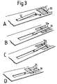
- Figure 3A shows finger 12 with the forward end 12A thereof raised above the level of base support upper surface 11A upon which the elasticised fabric piece 35 is supported.
- the raising of finger 12 is effected by activation of cylinder 28.
- Cylinder 24 is then activated to move the carrier to the right in Figure 1, until the carrier member 16 abuts the right hand end of base member 10. Finger 12 will now occupy the position shown in Figure 3B with the free end portions 12a above the marginal portion of the fabric piece 35.
- Cylinder 28 below the finger 12 is now lowered to bring the free end portion 12 thereof into gripping engagement with the fabric piece 35 ( Figure 3C) and the cylinder 30 is activated to raise the stop member 29 to a position behind the carrier member 16. Cylinder 24 is now activated to allow the carrier member 16 to return to an intermediate position as determined by the carrier member 16 abutting the stop member 29.
- the fabric piece is now held in position on the bench surface by the finger 12, a number of which are provided at spaced locations about the perimeter of the fabric piece.
- the finger 12 may be raised by the cylinder 28 therebelow and returned to abut the left hand end of base member 10 by deactivating the cylinder 24.
- the cylinder 28 below the finger 12 may be deactivated to permit the finger 12 to be lowered to its original position.
- the combined finger unit as above described with reference to Figures 1, 2 and 3 may be used to hold a fabric piece on a surface while the piece is folded as previously referred to.
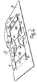
- FIG 4 of the drawings shows a fabric piece 40 supported on a flat table surface 41.
- the fabric piece is a blank for ladies' briefs having elasticised leg opening portions 42, elasticised waist band portions 43, and a gusset 44.
- the blank is held in position by eight combined finger units 45 of the construction previously described with reference to Figures 1, 2 and 3.
- the units are located at each end of the side edge portions 46 of the blank, which portions, when superimposed by folding the blank, will be sewn together by the side seams of the finished brief.
- the section 50 of the flat surface 41 is pivotally connected to the remainder of the flat surface along the line 51. Accordingly, by pivotal movement of the section 50 through 180° in an anticlockwise direction as seen in Figure 4, the two parts 40a and 40b of the blank are superimposed. In this superimposed position, the edges 46 of the blank are suitably aligned to be sewn together, such as by an overlocker.
- the pivoted section 50 is narrower than the fabric piece so that when the fabric has been folded the opposite edge portions 46 of the fabric piece are exposed. This enables holding bars (not shown) to be applied to these exposed portions and press them firmly against the surface of the table.
- the holding fingers of the combined finger units 45 may be lifted and withdrawn, and the pivotal section 50 of the bench returned to lie flat with the table top. It will be appreciated that the bench unfolds at the same time as the fingers 12 retract because otherwise the fingers could not be lifted.
- the upper surface of the folded fabric piece may then be engaged by a frictional gripping device having a frictional surface which will transport the fabric piece along the surface of the table to effect sewing of the side seams.
- a frictional gripping device having a frictional surface which will transport the fabric piece along the surface of the table to effect sewing of the side seams.
- the holding bars are raised and the frictional gripping device is then moved to slide the folded fabric piece over the surface of the bench in any selected path.
Landscapes
- Engineering & Computer Science (AREA)
- Textile Engineering (AREA)
- Sewing Machines And Sewing (AREA)
- Treatment Of Fiber Materials (AREA)
- Massaging Devices (AREA)
- Registering Or Overturning Sheets (AREA)
- Folding Of Thin Sheet-Like Materials, Special Discharging Devices, And Others (AREA)
- External Artificial Organs (AREA)
- Artificial Filaments (AREA)
- Manufacturing Cores, Coils, And Magnets (AREA)
- Materials For Medical Uses (AREA)
Claims (4)
Priority Applications (1)
| Application Number | Priority Date | Filing Date | Title |
|---|---|---|---|
| AT86901758T ATE47582T1 (de) | 1985-03-22 | 1986-03-21 | Vorrichtung fuer die behandlung geschmeidiger gewebe. |
Applications Claiming Priority (2)
| Application Number | Priority Date | Filing Date | Title |
|---|---|---|---|
| AU9868/85 | 1985-03-22 | ||
| AUPG986885 | 1985-03-22 |
Publications (3)
| Publication Number | Publication Date |
|---|---|
| EP0215855A1 EP0215855A1 (fr) | 1987-04-01 |
| EP0215855A4 EP0215855A4 (fr) | 1987-07-30 |
| EP0215855B1 true EP0215855B1 (fr) | 1989-10-25 |
Family
ID=3770995
Family Applications (1)
| Application Number | Title | Priority Date | Filing Date |
|---|---|---|---|
| EP86901758A Expired EP0215855B1 (fr) | 1985-03-22 | 1986-03-21 | Dispositif de manipulation de tissus souples |
Country Status (12)
| Country | Link |
|---|---|
| US (1) | US4811671A (fr) |
| EP (1) | EP0215855B1 (fr) |
| JP (1) | JPH0790952B2 (fr) |
| KR (1) | KR950006004B1 (fr) |
| AT (1) | ATE47582T1 (fr) |
| BR (1) | BR8606554A (fr) |
| CA (1) | CA1275599C (fr) |
| DE (1) | DE3666578D1 (fr) |
| IL (2) | IL78228A (fr) |
| MY (1) | MY100557A (fr) |
| SU (1) | SU1621808A3 (fr) |
| WO (1) | WO1986005467A1 (fr) |
Families Citing this family (4)
| Publication number | Priority date | Publication date | Assignee | Title |
|---|---|---|---|---|
| GB8500837D0 (en) * | 1985-01-14 | 1985-02-20 | Courtaulds Clothing Ltd | Laying-up workpieces of flexible sheet material |
| EG18225A (en) * | 1986-12-30 | 1992-09-30 | Pacifique Dunlop Limited | Improvement in or relating to the handling of limp fabric |
| GB2465543A (en) * | 2008-11-18 | 2010-05-26 | Concepts For Success | A process of manufacturing preformed hoops |
| GB2465544A (en) * | 2008-11-18 | 2010-05-26 | Christoph Schmitz | A manufacturing method for the making of articles comprising a hoop |
Family Cites Families (10)
| Publication number | Priority date | Publication date | Assignee | Title |
|---|---|---|---|---|
| US3869997A (en) * | 1967-03-30 | 1975-03-11 | Sidney German | Web cutting sewing machine and process |
| GB1238847A (fr) * | 1967-10-26 | 1971-07-14 | ||
| US3742878A (en) * | 1970-12-07 | 1973-07-03 | Warnaco Inc | Control for sewing machine |
| FR2291305A1 (fr) * | 1974-11-14 | 1976-06-11 | Duerkoppwerke | Tablette adaptable a une machine a coudre |
| US4066026A (en) * | 1976-02-20 | 1978-01-03 | Morris Dean Hunt | Work transport apparatus for use with a button attachment machine |
| IT1057013B (it) * | 1976-03-11 | 1982-03-10 | Rockell Rimoldi Spa | Dispositivo di guida di teli di tessuto provvisto di accessori quali tasche cinture o similari in una unita di cucitura |
| US4285506A (en) * | 1976-11-12 | 1981-08-25 | Weaver Nyal J | Cloth spreading and clamping apparatus |
| IT1130431B (it) * | 1980-05-16 | 1986-06-11 | Pizzardi P & C Omp Snc | Dispositivo di piegatura a palette perfezionato per apparecchiature destinate ad eseguire la piegatura ad alta velocita' e di buona qualita' di articoli di biancheria |
| US4396379A (en) * | 1980-10-16 | 1983-08-02 | Fmc Corporation | Thermoplastic bag stacking apparatus |
| DE3212629C2 (de) * | 1982-04-05 | 1985-03-14 | Herbert Kannegiesser Gmbh + Co, 4973 Vlotho | Vorrichtung zum Falten von Bekleidung, insbesondere Kittel |
-
1986
- 1986-03-21 DE DE8686901758T patent/DE3666578D1/de not_active Expired
- 1986-03-21 BR BR8606554A patent/BR8606554A/pt not_active IP Right Cessation
- 1986-03-21 EP EP86901758A patent/EP0215855B1/fr not_active Expired
- 1986-03-21 US US06/939,777 patent/US4811671A/en not_active Expired - Fee Related
- 1986-03-21 JP JP61501935A patent/JPH0790952B2/ja not_active Expired - Lifetime
- 1986-03-21 IL IL78228A patent/IL78228A/xx unknown
- 1986-03-21 WO PCT/AU1986/000074 patent/WO1986005467A1/fr not_active Ceased
- 1986-03-21 AT AT86901758T patent/ATE47582T1/de not_active IP Right Cessation
- 1986-03-21 IL IL78229A patent/IL78229A/xx unknown
- 1986-03-21 CA CA000504787A patent/CA1275599C/fr not_active Expired - Lifetime
- 1986-03-21 KR KR1019860700825A patent/KR950006004B1/ko not_active Expired - Fee Related
- 1986-11-21 SU SU864028633A patent/SU1621808A3/ru active
-
1987
- 1987-09-01 MY MYPI87001507A patent/MY100557A/en unknown
Also Published As
| Publication number | Publication date |
|---|---|
| ATE47582T1 (de) | 1989-11-15 |
| JPS62502397A (ja) | 1987-09-17 |
| KR870700567A (ko) | 1987-12-30 |
| WO1986005467A1 (fr) | 1986-09-25 |
| JPH0790952B2 (ja) | 1995-10-04 |
| EP0215855A1 (fr) | 1987-04-01 |
| KR950006004B1 (ko) | 1995-06-07 |
| DE3666578D1 (en) | 1989-11-30 |
| SU1621808A3 (ru) | 1991-01-15 |
| CA1275599C (fr) | 1990-10-30 |
| BR8606554A (pt) | 1987-08-04 |
| EP0215855A4 (fr) | 1987-07-30 |
| IL78228A (en) | 1991-12-12 |
| MY100557A (en) | 1990-11-15 |
| IL78229A (en) | 1991-12-15 |
| IL78228A0 (en) | 1986-07-31 |
| US4811671A (en) | 1989-03-14 |
Similar Documents
| Publication | Publication Date | Title |
|---|---|---|
| US6758377B2 (en) | Shirt finishing machine and cover put on torso | |
| JP2645987B2 (ja) | ベルトループ縫付けミシンにおけるテープの供給方法及びその装置 | |
| US2152940A (en) | Method of and means for folding wearing apparel | |
| US4903621A (en) | Hosiery toe closing method and apparatus | |
| US5016549A (en) | Attaching a strip of cloth with a zip-fastener component to a trouser forepart | |
| US4491255A (en) | Collapsible hosiery form | |
| US4811671A (en) | Handling limp fabric | |
| AU583914B2 (en) | Handling limp fabric | |
| US4464160A (en) | Method and apparatus for forming a hem in fabric flat goods | |
| JP2542317B2 (ja) | ストッキングの爪先の自動縫製機 | |
| TW212750B (en) | Shirt folding apparatus | |
| US3994485A (en) | Method and apparatus for sheet folding | |
| JP2533628B2 (ja) | リンプファブリックの処理方法および装置 | |
| JPS61257683A (ja) | 腰帯端部仕上用装置 | |
| US3568897A (en) | Method and apparatus for manufacturing garment parts | |
| JPH0284989A (ja) | ジーンズウエストベルトの角折り縫製方法及び縫製装置 | |
| KR800000799B1 (ko) | 의류 절첩(折疊) 및 프레스장치 | |
| US5349912A (en) | Pocket setter for flat and tabular garments | |
| JPH0358756B2 (fr) | ||
| JPH0613773U (ja) | 剣ボロ縫製機のセット装置 | |
| JPH0730980U (ja) | ミシンの布保持装置 | |
| JPH07100283A (ja) | タオル形成装置及びタオル形成方法 | |
| JPH0617675U (ja) | 玉縁縫いミシン | |
| JPH0698240B2 (ja) | 布開き装置 | |
| GB2192647A (en) | A fabric folder device |
Legal Events
| Date | Code | Title | Description |
|---|---|---|---|
| PUAI | Public reference made under article 153(3) epc to a published international application that has entered the european phase |
Free format text: ORIGINAL CODE: 0009012 |
|
| 17P | Request for examination filed |
Effective date: 19861118 |
|
| AK | Designated contracting states |
Kind code of ref document: A1 Designated state(s): AT BE CH DE FR GB IT LI LU NL SE |
|
| A4 | Supplementary search report drawn up and despatched |
Effective date: 19870730 |
|
| 17Q | First examination report despatched |
Effective date: 19880816 |
|
| GRAA | (expected) grant |
Free format text: ORIGINAL CODE: 0009210 |
|
| AK | Designated contracting states |
Kind code of ref document: B1 Designated state(s): AT BE CH DE FR GB IT LI LU NL SE |
|
| ITF | It: translation for a ep patent filed | ||
| REF | Corresponds to: |
Ref document number: 47582 Country of ref document: AT Date of ref document: 19891115 Kind code of ref document: T |
|
| REF | Corresponds to: |
Ref document number: 3666578 Country of ref document: DE Date of ref document: 19891130 |
|
| ET | Fr: translation filed | ||
| PLBE | No opposition filed within time limit |
Free format text: ORIGINAL CODE: 0009261 |
|
| STAA | Information on the status of an ep patent application or granted ep patent |
Free format text: STATUS: NO OPPOSITION FILED WITHIN TIME LIMIT |
|
| 26N | No opposition filed | ||
| ITTA | It: last paid annual fee | ||
| PGFP | Annual fee paid to national office [announced via postgrant information from national office to epo] |
Ref country code: SE Payment date: 19940228 Year of fee payment: 9 Ref country code: LU Payment date: 19940228 Year of fee payment: 9 |
|
| EPTA | Lu: last paid annual fee | ||
| PGFP | Annual fee paid to national office [announced via postgrant information from national office to epo] |
Ref country code: NL Payment date: 19940331 Year of fee payment: 9 |
|
| EAL | Se: european patent in force in sweden |
Ref document number: 86901758.2 |
|
| PG25 | Lapsed in a contracting state [announced via postgrant information from national office to epo] |
Ref country code: LU Free format text: LAPSE BECAUSE OF NON-PAYMENT OF DUE FEES Effective date: 19950321 |
|
| PG25 | Lapsed in a contracting state [announced via postgrant information from national office to epo] |
Ref country code: SE Effective date: 19950322 |
|
| PG25 | Lapsed in a contracting state [announced via postgrant information from national office to epo] |
Ref country code: NL Effective date: 19951001 |
|
| NLV4 | Nl: lapsed or anulled due to non-payment of the annual fee |
Effective date: 19951001 |
|
| EUG | Se: european patent has lapsed |
Ref document number: 86901758.2 |
|
| PGFP | Annual fee paid to national office [announced via postgrant information from national office to epo] |
Ref country code: FR Payment date: 19960117 Year of fee payment: 11 |
|
| PGFP | Annual fee paid to national office [announced via postgrant information from national office to epo] |
Ref country code: CH Payment date: 19960301 Year of fee payment: 11 |
|
| PGFP | Annual fee paid to national office [announced via postgrant information from national office to epo] |
Ref country code: GB Payment date: 19960312 Year of fee payment: 11 |
|
| PGFP | Annual fee paid to national office [announced via postgrant information from national office to epo] |
Ref country code: BE Payment date: 19960313 Year of fee payment: 11 |
|
| PGFP | Annual fee paid to national office [announced via postgrant information from national office to epo] |
Ref country code: AT Payment date: 19960328 Year of fee payment: 11 |
|
| PGFP | Annual fee paid to national office [announced via postgrant information from national office to epo] |
Ref country code: DE Payment date: 19960531 Year of fee payment: 11 |
|
| PG25 | Lapsed in a contracting state [announced via postgrant information from national office to epo] |
Ref country code: GB Effective date: 19970321 Ref country code: AT Effective date: 19970321 |
|
| PG25 | Lapsed in a contracting state [announced via postgrant information from national office to epo] |
Ref country code: LI Effective date: 19970331 Ref country code: CH Effective date: 19970331 Ref country code: BE Effective date: 19970331 |
|
| BERE | Be: lapsed |
Owner name: PACIFIC DUNLOP LTD Effective date: 19970331 |
|
| GBPC | Gb: european patent ceased through non-payment of renewal fee |
Effective date: 19970321 |
|
| REG | Reference to a national code |
Ref country code: CH Ref legal event code: PL |
|
| PG25 | Lapsed in a contracting state [announced via postgrant information from national office to epo] |
Ref country code: FR Free format text: LAPSE BECAUSE OF NON-PAYMENT OF DUE FEES Effective date: 19971128 |
|
| PG25 | Lapsed in a contracting state [announced via postgrant information from national office to epo] |
Ref country code: DE Effective date: 19971202 |
|
| REG | Reference to a national code |
Ref country code: FR Ref legal event code: ST |
|
| PG25 | Lapsed in a contracting state [announced via postgrant information from national office to epo] |
Ref country code: IT Free format text: LAPSE BECAUSE OF NON-PAYMENT OF DUE FEES Effective date: 20050321 |