EP0221396A1 - Elektrisch schweissbare Muffe - Google Patents
Elektrisch schweissbare Muffe Download PDFInfo
- Publication number
- EP0221396A1 EP0221396A1 EP19860114078 EP86114078A EP0221396A1 EP 0221396 A1 EP0221396 A1 EP 0221396A1 EP 19860114078 EP19860114078 EP 19860114078 EP 86114078 A EP86114078 A EP 86114078A EP 0221396 A1 EP0221396 A1 EP 0221396A1
- Authority
- EP
- European Patent Office
- Prior art keywords
- sleeve
- bore
- fusing
- coupler
- pipe sections
- Prior art date
- Legal status (The legal status is an assumption and is not a legal conclusion. Google has not performed a legal analysis and makes no representation as to the accuracy of the status listed.)
- Granted
Links
- 239000000463 material Substances 0.000 claims abstract description 50
- 238000010438 heat treatment Methods 0.000 claims abstract description 15
- 239000004033 plastic Substances 0.000 claims abstract description 15
- 229920003023 plastic Polymers 0.000 claims abstract description 15
- 230000009969 flowable effect Effects 0.000 claims abstract description 6
- 230000000007 visual effect Effects 0.000 claims abstract description 6
- 229920001169 thermoplastic Polymers 0.000 claims description 24
- 239000004416 thermosoftening plastic Substances 0.000 claims description 24
- 230000000694 effects Effects 0.000 claims description 5
- 230000000630 rising effect Effects 0.000 claims description 3
- 238000004804 winding Methods 0.000 description 5
- 238000003466 welding Methods 0.000 description 3
- 238000010276 construction Methods 0.000 description 2
- 238000000034 method Methods 0.000 description 2
- 238000000465 moulding Methods 0.000 description 2
- 230000015572 biosynthetic process Effects 0.000 description 1
- 239000003086 colorant Substances 0.000 description 1
- 238000002788 crimping Methods 0.000 description 1
- 239000012530 fluid Substances 0.000 description 1
- 238000005755 formation reaction Methods 0.000 description 1
- 230000004927 fusion Effects 0.000 description 1
- 238000011065 in-situ storage Methods 0.000 description 1
- 238000004519 manufacturing process Methods 0.000 description 1
Images


Classifications
-
- F—MECHANICAL ENGINEERING; LIGHTING; HEATING; WEAPONS; BLASTING
- F16—ENGINEERING ELEMENTS AND UNITS; GENERAL MEASURES FOR PRODUCING AND MAINTAINING EFFECTIVE FUNCTIONING OF MACHINES OR INSTALLATIONS; THERMAL INSULATION IN GENERAL
- F16L—PIPES; JOINTS OR FITTINGS FOR PIPES; SUPPORTS FOR PIPES, CABLES OR PROTECTIVE TUBING; MEANS FOR THERMAL INSULATION IN GENERAL
- F16L47/00—Connecting arrangements or other fittings specially adapted to be made of plastics or to be used with pipes made of plastics
- F16L47/02—Welded joints; Adhesive joints
- F16L47/03—Welded joints with an electrical resistance incorporated in the joint
-
- B—PERFORMING OPERATIONS; TRANSPORTING
- B29—WORKING OF PLASTICS; WORKING OF SUBSTANCES IN A PLASTIC STATE IN GENERAL
- B29C—SHAPING OR JOINING OF PLASTICS; SHAPING OF MATERIAL IN A PLASTIC STATE, NOT OTHERWISE PROVIDED FOR; AFTER-TREATMENT OF THE SHAPED PRODUCTS, e.g. REPAIRING
- B29C65/00—Joining or sealing of preformed parts, e.g. welding of plastics materials; Apparatus therefor
- B29C65/02—Joining or sealing of preformed parts, e.g. welding of plastics materials; Apparatus therefor by heating, with or without pressure
- B29C65/34—Joining or sealing of preformed parts, e.g. welding of plastics materials; Apparatus therefor by heating, with or without pressure using heated elements which remain in the joint, e.g. "verlorenes Schweisselement"
- B29C65/3404—Joining or sealing of preformed parts, e.g. welding of plastics materials; Apparatus therefor by heating, with or without pressure using heated elements which remain in the joint, e.g. "verlorenes Schweisselement" characterised by the type of heated elements which remain in the joint
- B29C65/342—Joining or sealing of preformed parts, e.g. welding of plastics materials; Apparatus therefor by heating, with or without pressure using heated elements which remain in the joint, e.g. "verlorenes Schweisselement" characterised by the type of heated elements which remain in the joint comprising at least a single wire, e.g. in the form of a winding
-
- B—PERFORMING OPERATIONS; TRANSPORTING
- B29—WORKING OF PLASTICS; WORKING OF SUBSTANCES IN A PLASTIC STATE IN GENERAL
- B29C—SHAPING OR JOINING OF PLASTICS; SHAPING OF MATERIAL IN A PLASTIC STATE, NOT OTHERWISE PROVIDED FOR; AFTER-TREATMENT OF THE SHAPED PRODUCTS, e.g. REPAIRING
- B29C65/00—Joining or sealing of preformed parts, e.g. welding of plastics materials; Apparatus therefor
- B29C65/02—Joining or sealing of preformed parts, e.g. welding of plastics materials; Apparatus therefor by heating, with or without pressure
- B29C65/34—Joining or sealing of preformed parts, e.g. welding of plastics materials; Apparatus therefor by heating, with or without pressure using heated elements which remain in the joint, e.g. "verlorenes Schweisselement"
- B29C65/3468—Joining or sealing of preformed parts, e.g. welding of plastics materials; Apparatus therefor by heating, with or without pressure using heated elements which remain in the joint, e.g. "verlorenes Schweisselement" characterised by the means for supplying heat to said heated elements which remain in the join, e.g. special electrical connectors of windings
-
- B—PERFORMING OPERATIONS; TRANSPORTING
- B29—WORKING OF PLASTICS; WORKING OF SUBSTANCES IN A PLASTIC STATE IN GENERAL
- B29C—SHAPING OR JOINING OF PLASTICS; SHAPING OF MATERIAL IN A PLASTIC STATE, NOT OTHERWISE PROVIDED FOR; AFTER-TREATMENT OF THE SHAPED PRODUCTS, e.g. REPAIRING
- B29C66/00—General aspects of processes or apparatus for joining preformed parts
- B29C66/01—General aspects dealing with the joint area or with the area to be joined
- B29C66/05—Particular design of joint configurations
- B29C66/10—Particular design of joint configurations particular design of the joint cross-sections
- B29C66/11—Joint cross-sections comprising a single joint-segment, i.e. one of the parts to be joined comprising a single joint-segment in the joint cross-section
- B29C66/112—Single lapped joints
- B29C66/1122—Single lap to lap joints, i.e. overlap joints
-
- B—PERFORMING OPERATIONS; TRANSPORTING
- B29—WORKING OF PLASTICS; WORKING OF SUBSTANCES IN A PLASTIC STATE IN GENERAL
- B29C—SHAPING OR JOINING OF PLASTICS; SHAPING OF MATERIAL IN A PLASTIC STATE, NOT OTHERWISE PROVIDED FOR; AFTER-TREATMENT OF THE SHAPED PRODUCTS, e.g. REPAIRING
- B29C66/00—General aspects of processes or apparatus for joining preformed parts
- B29C66/01—General aspects dealing with the joint area or with the area to be joined
- B29C66/05—Particular design of joint configurations
- B29C66/10—Particular design of joint configurations particular design of the joint cross-sections
- B29C66/12—Joint cross-sections combining only two joint-segments; Tongue and groove joints; Tenon and mortise joints; Stepped joint cross-sections
- B29C66/122—Joint cross-sections combining only two joint-segments, i.e. one of the parts to be joined comprising only two joint-segments in the joint cross-section
- B29C66/1222—Joint cross-sections combining only two joint-segments, i.e. one of the parts to be joined comprising only two joint-segments in the joint cross-section comprising at least a lapped joint-segment
-
- B—PERFORMING OPERATIONS; TRANSPORTING
- B29—WORKING OF PLASTICS; WORKING OF SUBSTANCES IN A PLASTIC STATE IN GENERAL
- B29C—SHAPING OR JOINING OF PLASTICS; SHAPING OF MATERIAL IN A PLASTIC STATE, NOT OTHERWISE PROVIDED FOR; AFTER-TREATMENT OF THE SHAPED PRODUCTS, e.g. REPAIRING
- B29C66/00—General aspects of processes or apparatus for joining preformed parts
- B29C66/01—General aspects dealing with the joint area or with the area to be joined
- B29C66/05—Particular design of joint configurations
- B29C66/10—Particular design of joint configurations particular design of the joint cross-sections
- B29C66/12—Joint cross-sections combining only two joint-segments; Tongue and groove joints; Tenon and mortise joints; Stepped joint cross-sections
- B29C66/122—Joint cross-sections combining only two joint-segments, i.e. one of the parts to be joined comprising only two joint-segments in the joint cross-section
- B29C66/1224—Joint cross-sections combining only two joint-segments, i.e. one of the parts to be joined comprising only two joint-segments in the joint cross-section comprising at least a butt joint-segment
-
- B—PERFORMING OPERATIONS; TRANSPORTING
- B29—WORKING OF PLASTICS; WORKING OF SUBSTANCES IN A PLASTIC STATE IN GENERAL
- B29C—SHAPING OR JOINING OF PLASTICS; SHAPING OF MATERIAL IN A PLASTIC STATE, NOT OTHERWISE PROVIDED FOR; AFTER-TREATMENT OF THE SHAPED PRODUCTS, e.g. REPAIRING
- B29C66/00—General aspects of processes or apparatus for joining preformed parts
- B29C66/50—General aspects of joining tubular articles; General aspects of joining long products, i.e. bars or profiled elements; General aspects of joining single elements to tubular articles, hollow articles or bars; General aspects of joining several hollow-preforms to form hollow or tubular articles
- B29C66/51—Joining tubular articles, profiled elements or bars; Joining single elements to tubular articles, hollow articles or bars; Joining several hollow-preforms to form hollow or tubular articles
- B29C66/52—Joining tubular articles, bars or profiled elements
- B29C66/522—Joining tubular articles
- B29C66/5221—Joining tubular articles for forming coaxial connections, i.e. the tubular articles to be joined forming a zero angle relative to each other
-
- B—PERFORMING OPERATIONS; TRANSPORTING
- B29—WORKING OF PLASTICS; WORKING OF SUBSTANCES IN A PLASTIC STATE IN GENERAL
- B29C—SHAPING OR JOINING OF PLASTICS; SHAPING OF MATERIAL IN A PLASTIC STATE, NOT OTHERWISE PROVIDED FOR; AFTER-TREATMENT OF THE SHAPED PRODUCTS, e.g. REPAIRING
- B29C66/00—General aspects of processes or apparatus for joining preformed parts
- B29C66/50—General aspects of joining tubular articles; General aspects of joining long products, i.e. bars or profiled elements; General aspects of joining single elements to tubular articles, hollow articles or bars; General aspects of joining several hollow-preforms to form hollow or tubular articles
- B29C66/51—Joining tubular articles, profiled elements or bars; Joining single elements to tubular articles, hollow articles or bars; Joining several hollow-preforms to form hollow or tubular articles
- B29C66/52—Joining tubular articles, bars or profiled elements
- B29C66/522—Joining tubular articles
- B29C66/5229—Joining tubular articles involving the use of a socket
- B29C66/52291—Joining tubular articles involving the use of a socket said socket comprising a stop
- B29C66/52292—Joining tubular articles involving the use of a socket said socket comprising a stop said stop being internal
-
- B—PERFORMING OPERATIONS; TRANSPORTING
- B29—WORKING OF PLASTICS; WORKING OF SUBSTANCES IN A PLASTIC STATE IN GENERAL
- B29C—SHAPING OR JOINING OF PLASTICS; SHAPING OF MATERIAL IN A PLASTIC STATE, NOT OTHERWISE PROVIDED FOR; AFTER-TREATMENT OF THE SHAPED PRODUCTS, e.g. REPAIRING
- B29C66/00—General aspects of processes or apparatus for joining preformed parts
- B29C66/90—Measuring or controlling the joining process
- B29C66/91—Measuring or controlling the joining process by measuring or controlling the temperature, the heat or the thermal flux
- B29C66/912—Measuring or controlling the joining process by measuring or controlling the temperature, the heat or the thermal flux by measuring the temperature, the heat or the thermal flux
- B29C66/9121—Measuring or controlling the joining process by measuring or controlling the temperature, the heat or the thermal flux by measuring the temperature, the heat or the thermal flux by measuring the temperature
- B29C66/91211—Measuring or controlling the joining process by measuring or controlling the temperature, the heat or the thermal flux by measuring the temperature, the heat or the thermal flux by measuring the temperature with special temperature measurement means or methods
- B29C66/91218—Measuring or controlling the joining process by measuring or controlling the temperature, the heat or the thermal flux by measuring the temperature, the heat or the thermal flux by measuring the temperature with special temperature measurement means or methods using colour change, e.g. using separate colour indicators
-
- B—PERFORMING OPERATIONS; TRANSPORTING
- B29—WORKING OF PLASTICS; WORKING OF SUBSTANCES IN A PLASTIC STATE IN GENERAL
- B29C—SHAPING OR JOINING OF PLASTICS; SHAPING OF MATERIAL IN A PLASTIC STATE, NOT OTHERWISE PROVIDED FOR; AFTER-TREATMENT OF THE SHAPED PRODUCTS, e.g. REPAIRING
- B29C66/00—General aspects of processes or apparatus for joining preformed parts
- B29C66/90—Measuring or controlling the joining process
- B29C66/91—Measuring or controlling the joining process by measuring or controlling the temperature, the heat or the thermal flux
- B29C66/912—Measuring or controlling the joining process by measuring or controlling the temperature, the heat or the thermal flux by measuring the temperature, the heat or the thermal flux
- B29C66/9121—Measuring or controlling the joining process by measuring or controlling the temperature, the heat or the thermal flux by measuring the temperature, the heat or the thermal flux by measuring the temperature
- B29C66/91221—Measuring or controlling the joining process by measuring or controlling the temperature, the heat or the thermal flux by measuring the temperature, the heat or the thermal flux by measuring the temperature of the parts to be joined
-
- B—PERFORMING OPERATIONS; TRANSPORTING
- B29—WORKING OF PLASTICS; WORKING OF SUBSTANCES IN A PLASTIC STATE IN GENERAL
- B29C—SHAPING OR JOINING OF PLASTICS; SHAPING OF MATERIAL IN A PLASTIC STATE, NOT OTHERWISE PROVIDED FOR; AFTER-TREATMENT OF THE SHAPED PRODUCTS, e.g. REPAIRING
- B29C66/00—General aspects of processes or apparatus for joining preformed parts
- B29C66/90—Measuring or controlling the joining process
- B29C66/97—Checking completion of joining or correct joining by using indications on at least one of the joined parts
- B29C66/972—Checking completion of joining or correct joining by using indications on at least one of the joined parts by extrusion of molten material
-
- B—PERFORMING OPERATIONS; TRANSPORTING
- B29—WORKING OF PLASTICS; WORKING OF SUBSTANCES IN A PLASTIC STATE IN GENERAL
- B29C—SHAPING OR JOINING OF PLASTICS; SHAPING OF MATERIAL IN A PLASTIC STATE, NOT OTHERWISE PROVIDED FOR; AFTER-TREATMENT OF THE SHAPED PRODUCTS, e.g. REPAIRING
- B29C65/00—Joining or sealing of preformed parts, e.g. welding of plastics materials; Apparatus therefor
- B29C65/02—Joining or sealing of preformed parts, e.g. welding of plastics materials; Apparatus therefor by heating, with or without pressure
- B29C65/34—Joining or sealing of preformed parts, e.g. welding of plastics materials; Apparatus therefor by heating, with or without pressure using heated elements which remain in the joint, e.g. "verlorenes Schweisselement"
- B29C65/3472—Joining or sealing of preformed parts, e.g. welding of plastics materials; Apparatus therefor by heating, with or without pressure using heated elements which remain in the joint, e.g. "verlorenes Schweisselement" characterised by the composition of the heated elements which remain in the joint
- B29C65/3476—Joining or sealing of preformed parts, e.g. welding of plastics materials; Apparatus therefor by heating, with or without pressure using heated elements which remain in the joint, e.g. "verlorenes Schweisselement" characterised by the composition of the heated elements which remain in the joint being metallic
-
- B—PERFORMING OPERATIONS; TRANSPORTING
- B29—WORKING OF PLASTICS; WORKING OF SUBSTANCES IN A PLASTIC STATE IN GENERAL
- B29C—SHAPING OR JOINING OF PLASTICS; SHAPING OF MATERIAL IN A PLASTIC STATE, NOT OTHERWISE PROVIDED FOR; AFTER-TREATMENT OF THE SHAPED PRODUCTS, e.g. REPAIRING
- B29C66/00—General aspects of processes or apparatus for joining preformed parts
- B29C66/90—Measuring or controlling the joining process
- B29C66/94—Measuring or controlling the joining process by measuring or controlling the time
-
- Y—GENERAL TAGGING OF NEW TECHNOLOGICAL DEVELOPMENTS; GENERAL TAGGING OF CROSS-SECTIONAL TECHNOLOGIES SPANNING OVER SEVERAL SECTIONS OF THE IPC; TECHNICAL SUBJECTS COVERED BY FORMER USPC CROSS-REFERENCE ART COLLECTIONS [XRACs] AND DIGESTS
- Y10—TECHNICAL SUBJECTS COVERED BY FORMER USPC
- Y10T—TECHNICAL SUBJECTS COVERED BY FORMER US CLASSIFICATION
- Y10T29/00—Metal working
- Y10T29/49—Method of mechanical manufacture
- Y10T29/49002—Electrical device making
- Y10T29/49082—Resistor making
- Y10T29/49083—Heater type
Definitions
- THIS INVENTION relates to an electrofusion coupler for use in the construction of thermoplastics pipe systems wherein a welded joint between adjoining ends of adjoining sections of plastics pipe, or of such a pipe section and a tubular member forming part of the pipe fitting, valve or the like, is obtained by forcing such adjoining ends into such an electrofusion coupler and energising the same.
- Such an electrofusion coupler takes the form of a sleeve of thermoplastics material having an electrical resistance heater embedded therein and extended around the sleeve.
- an electrical resistance heater embedded therein and extended around the sleeve.
- the electrical resistance wire takes the form of coil embedded in the thermoplastics sleeve and coaxial therewith, the wire lying close to the inner surface of the sleeve, the ends of the wire being connected to terminal points, exposed on the exterior of the sleeve for connection to a source of electrical current.
- thermoplastics pipe systems using electrofusion couplers of this kind, it is desirable to have some reliable yet inexpensive means for determining whether the interior of the sleeve, and the inserted pipe end or the like have been sufficiently heated to afford a good welded joint or whether it is necessary to re-make the joint.
- an electrofusion coupler comprising a sleeve of thermoplastics material having embedded therein, near to the inner surface thereof, an electrical resistance heater extended around the circumference of the sleeve, the coupler having visual indicating means afforded by at least one blind bore extending into the sleeve from the exterior thereof, the spacing of the inner end of said bore from the inner surface of the sleeve, and the diameter of the said bore, being so selected that in use, when the free ends of two thermoplastics pipe sections to be joined together are fitted closely within the sleeve and the electrical resistance heater is supplied with electrical current to fuse the region of the sleeve adjacent the pipe sections and the outer surfaces of the pipe sections together, if the energy supplied has been adequate to effect proper fusing, the softened flowable plastics material is urged by the pressure produced by heating and fusing the same to rise within said bore to project from the outer surface of the sleeve.
- an electrofusion coupler comprising a sleeve of thermoplastics material incorporating an inner layer of thermoplastics material of a first colour, an electrical resistance heater extended around the inner layer, and an outer layer of thermoplastics material of a contrasting colour extending around the inner layer and said electrical resistance heater, the coupler having a visual indicator afforded by at least one blind extending into the sleeve from the exterior thereof, the spacing of the inner end of said bore from the inner surface of the sleeve, and the diameter of the said bore, being so selected that in use, when the free ends of two thermoplastics pipe sections to be joined together are fitted closely within the sleeve and the electrical resistance heater is supplied with electrical current to fuse the region of the sleeve adjacent the pipe sections and the outer surfaces of the pipe sections together, if the energy supplied has been adequate to effect proper fusing, the softened flowable plastics material is urged by the pressure produced by heating and fusing the same to rise within said bore
- an electrofusion coupler takes the form of a substantially cylindrical sleeve comprising an inner layer 10 of thermoplastics material, a coil of electrical resistance heating wire wound round the sleeve 10 from adjacent one end thereof to the other end thereof and an outer layer 14 of thermoplastics material surrounding the inner layer 10 and the coil of heating wire.
- the ends of the coil of heating wire are wrapped around pegs 16 integral with the inner layer and over which are fitted, in good electrical contact with the wrapped ends of the heating wire, terminal plugs 18 located within cylindrical sockets 20 formed integrally with the outer layer 14.
- formations 22 project inwardly to act as stops for the ends of inserted pipe sections.
- the ends of two pipe sections to be united using the connector are inserted into the sleeve from the opposite ends thereof until the pipe sections engage the stops 22. There are then inserted into the sockets 20, to make electrical contact with the plugs 18, respective electrical connectors by which electrical current is passed through the resistance wire for a predetermined period of time.
- the resistance wire fuses the adjoining material of the inner and outer sleeve and ultimately the material of the peripheries of the pipe sections inserted in the connector are melted or fused so that the pipe sections are welded to the connector and are thus sealingly connected with one another.
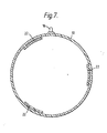
- the coupler is manufactured as follows. Firstly, as illustrated in Figure 6, the inner layer 10 is formed as a thermoplastics moulding taking the form of a thin sleeve of thermoplastics material having, projecting radially adjacent to either end thereof, respective pegs 16. The thin sleeve forming the inner layer is then wound with the resistance heating wire to provide a helical winding extending from adjacent the inner side of one peg 16 to adjacent the inner side of the other.
- the resistance heating wire is continuously heated, by passing electric current therethrough, and as a result, by virtue of the tension exerted on the wire during the winding, the wire becomes embedded in the outer part of the inner sleeve, effectively forming a helical groove to accommodate itself, as shown in Figures 4 and 5, where the wire is indicated at 17.
- the ends of the wire 17 are then wrapped around the respective pegs 16 and the plugs 18 are fitted over the wrapped pegs 16 and so secured as to ensure good electrical contact between the wire ends 4 and the plugs 18.
- the electrical connection between the ends of the resistance heating wire 17 and the plugs 18 may be effected by electrical resistance welding or by crimping the tubular lower end portions of the plugs 18 which receive the pegs 16 or by any other appropriate method.
- the manner in which the resistance heating wire is wrapped on the sleeve ensures that adjacent turns of the coil can be made to lie in close proximity to one another but are nevertheless insulated electrically from one another and are held in position by the plastics material between adjacent grooves formed by the wire during the winding process.
- the wound inner sleeve is fitted within an appropriate mould and the outer layer 14 moulded therearound, together with the sockets 20.
- two blind bores 24 are also moulded extending from the outer surface of the outer layer to adjacent the inner layer (see Figure 5) so that a thin diaphragm or web 30 of the plastics material of the outer layer is provided at the bottom of each bore.
- this pressure is sufficient to rupture the diaphragms 30 and to cause the fused and molten plastics material to be forced upwardly through the blind bores 24 to project in a bulb or dome therefrom as indicated in broken lines at 36 in Figure 5.
- the outer layer 14 will also be a thermoplastics material and may be of substantially the same composition as the inner sleeve and thus, when the material of the inner layer has become fused, the material of the outer layer, which closely adjoins the inner layer, and including the diaphragm, will also have become fused or softened to some extent.
- the diaphragm 30 will have softened and become partially fused by the time that the material of the inner sleeve has become fused and pressurised, and as a result, the material of the diaphragm 30 will rise within the bore 24 with the overlying material of the sleeve 10 forming an outer layer of the rising plug of plastics.
- the rupture of the diaphragm will effectively arise partially from a thinning of the diaphragm and the actual rupture may not take place until the rising plastics material has reached or almost reached the outer end of the bore 24.
- the inner layer 14 and outer layer 10 are of contrasting colours so that the workman using the coupler can determine, by the projection of the contrasting bulbs of colour above the outer surface of the outer layer, that a satisfactory weld has been achieved.
- the inner sleeve and outer sleeve it is possible for the inner sleeve and outer sleeve to be of the same colour, as the emergence of the bulbs of fused material from the inner layer through the bores is clearly detectable visually, although somewhat less striking if these bulbs are of the same colour as the outer material.
- the bores 24 may extend right through to the inner layer, so that instead of being closed at its inner end by a diaphragm of the material of the outer layer, each bore 24 is simply closed at its inner end by the inner layer 10, or each diaphragm 30 instead of extending completely across the inner end of the receptive bore 24 may have a central aperture exposing the inner layer.
- each bore 24 will be from 10 to 30 mm from the adjoining end of the coupler (dimension A in Figure 3). It will be noted from Figure 3 that the bores 24 are offset laterally from the central plane in which the plugs are located. This is simply for convenience of manufacture and to ensure that the bores are not obstructed by the electrical connections to the plugs in use.
- the amount of the offset (dimension B in Figure 2) may vary from no offset at all to around 5 mm.
- the diameter of the bores 24 may vary from 1.5 mm to 6.5 mm for instance.
- the appropriate dimensions are interrrelated with one another and with the coupler dimensions, the thermoplastics material used etc., the appropriate combination of dimensions etc., must be determined experimentally in each case and the dimensions suggested above are merely exemplary. Likewise the thickness of the diaphragm 30 will vary from coupler to coupler and the appropriate thickness may generally be determined experimentally.
Landscapes
- Engineering & Computer Science (AREA)
- Mechanical Engineering (AREA)
- Physics & Mathematics (AREA)
- Thermal Sciences (AREA)
- General Engineering & Computer Science (AREA)
- Lining Or Joining Of Plastics Or The Like (AREA)
- Branch Pipes, Bends, And The Like (AREA)
- Quick-Acting Or Multi-Walled Pipe Joints (AREA)
- Connections Effected By Soldering, Adhesion, Or Permanent Deformation (AREA)
- Thermotherapy And Cooling Therapy Devices (AREA)
- Liquid Developers In Electrophotography (AREA)
- Conductive Materials (AREA)
- Organic Insulating Materials (AREA)
- Insulating Bodies (AREA)
Priority Applications (1)
| Application Number | Priority Date | Filing Date | Title |
|---|---|---|---|
| AT86114078T ATE50850T1 (de) | 1985-10-24 | 1986-10-10 | Elektrisch schweissbare muffe. |
Applications Claiming Priority (2)
| Application Number | Priority Date | Filing Date | Title |
|---|---|---|---|
| GB8526235 | 1985-10-24 | ||
| GB8526235A GB8526235D0 (en) | 1985-10-24 | 1985-10-24 | Electrofusion coupler |
Publications (2)
| Publication Number | Publication Date |
|---|---|
| EP0221396A1 true EP0221396A1 (de) | 1987-05-13 |
| EP0221396B1 EP0221396B1 (de) | 1990-03-07 |
Family
ID=10587182
Family Applications (1)
| Application Number | Title | Priority Date | Filing Date |
|---|---|---|---|
| EP19860114078 Expired - Lifetime EP0221396B1 (de) | 1985-10-24 | 1986-10-10 | Elektrisch schweissbare Muffe |
Country Status (11)
| Country | Link |
|---|---|
| US (1) | US4727242A (de) |
| EP (1) | EP0221396B1 (de) |
| AT (1) | ATE50850T1 (de) |
| AU (1) | AU586038B2 (de) |
| CA (1) | CA1260663A (de) |
| DE (1) | DE3669382D1 (de) |
| DK (1) | DK165521C (de) |
| ES (1) | ES2011763B3 (de) |
| GB (1) | GB8526235D0 (de) |
| NZ (1) | NZ217820A (de) |
| ZA (1) | ZA868054B (de) |
Cited By (6)
| Publication number | Priority date | Publication date | Assignee | Title |
|---|---|---|---|---|
| FR2643014A1 (fr) * | 1988-12-29 | 1990-08-17 | Gaz De France | Dispositif pour detecter, au cours du soudage, des variations dans l'etat physique de la matiere plastique d'une piece de raccordement prevue pour la jonction de tubes |
| EP0378406A3 (de) * | 1989-01-11 | 1991-06-12 | Osaka Gas Co., Ltd. | Elektroschweissverbindung und deren Verwendung in einem Heisswasserverteiler |
| EP0396273A3 (de) * | 1989-05-03 | 1993-09-08 | Fusion Group Plc | Elektroschweissmuffen |
| WO1996029194A1 (en) * | 1995-03-21 | 1996-09-26 | Uponor Limited | Manufacture of electrofusion fittings |
| US5697143A (en) * | 1994-04-28 | 1997-12-16 | Glynwed Plastics Ltd. | Method of manufacturing an electrofusion coupler |
| GB2571924A (en) * | 2018-03-07 | 2019-09-18 | Subsea 7 Ltd | Electrofusion fittings for lined pipes |
Families Citing this family (29)
| Publication number | Priority date | Publication date | Assignee | Title |
|---|---|---|---|---|
| US4931116A (en) * | 1986-05-27 | 1990-06-05 | Raychem Corporation | Heat-recoverable coupler |
| CH672014A5 (de) * | 1986-08-29 | 1989-10-13 | Fischer Ag Georg | |
| GB2194749A (en) * | 1986-09-09 | 1988-03-16 | Du Pont | Method of manufacturing heat-weldable thermoplastic fittings |
| NL8700299A (nl) * | 1987-02-09 | 1988-09-01 | Wavin Bv | Lasmof uit thermoplastische kunststof, werkwijze voor het vormen van een dergelijke lasmof alsmede gereedschap voor gebruik bij het uitvoeren van een dergelijke werkwijze. |
| JPH0536669Y2 (de) * | 1987-10-22 | 1993-09-16 | ||
| CA1321626C (en) * | 1988-07-21 | 1993-08-24 | Naotake Uda | Electrofusion of electrofusion joint, method of confirming state of fusion and fusion joint suitable for use in the methods |
| US5228186A (en) * | 1989-05-03 | 1993-07-20 | Fusion Plastics Ltd. | Method of manufacturing electro-fusion fittings |
| DE4203626C2 (de) * | 1992-02-08 | 1993-11-04 | Fischer Georg Rohrleitung | Schweissmuffe und verfahren zu deren herstellung |
| US5369248A (en) * | 1992-09-01 | 1994-11-29 | Gaz De France | Electro-weldable connecting piece having connection terminals and its method of manufacture |
| US5566988A (en) * | 1993-04-30 | 1996-10-22 | The Gates Rubber Company | Heat shrinkable hose clamp with indicator |
| US5531483A (en) * | 1993-12-06 | 1996-07-02 | The Gates Rubber Company | Heat shrinkable hose clamp with heating indicator |
| GB9406591D0 (en) * | 1994-03-31 | 1994-05-25 | Glynwed Plastics | Improvements in or relating to electrofusion couplers |
| GB2304163B (en) * | 1995-08-05 | 1999-03-17 | Uponor Ltd | Pipe joint and electrofusion coupling therefor |
| US5708251A (en) * | 1995-10-30 | 1998-01-13 | Compucraft Ltd. | Method for embedding resistance heating wire in an electrofusion saddle coupler |
| GB2323507B (en) * | 1997-03-21 | 2000-11-29 | Ceramaspeed Ltd | Electric heater unit and method of manufacture |
| US6883835B2 (en) | 2001-03-05 | 2005-04-26 | Basic Resources, Inc. | Polyfusion pipe repair system and method |
| US6857670B2 (en) | 2001-12-05 | 2005-02-22 | Cuno Incorporated | Plastic tube joint |
| US6870143B2 (en) * | 2002-04-18 | 2005-03-22 | Basic Resources, Inc. | System and method for encapsulating a pipe |
| US7156423B2 (en) * | 2003-04-11 | 2007-01-02 | 3M Innovative Properties Company | Plastic tube joint |
| US20060202471A1 (en) * | 2005-03-07 | 2006-09-14 | Weisbond Bradley K | Electro-fusion joining system for thermoplastic piping systems |
| CA2499849C (en) * | 2005-03-09 | 2010-02-02 | Zcl Composites Inc. | Composite laminated sheet material for containment sumps |
| US20100295299A1 (en) * | 2007-06-12 | 2010-11-25 | Orion Enterprises, Inc. | Joint and joining method for plastic pipe |
| DK2486310T3 (da) | 2009-10-06 | 2020-05-18 | Prinsco Inc | Varmesmeltelig pakning og fremgangsmåde til fremstilling heraf |
| GB201204294D0 (en) * | 2012-03-12 | 2012-04-25 | Pioneer Lining Technology Ltd | Electrofusion fitting |
| US9296153B2 (en) | 2013-05-01 | 2016-03-29 | Watts Water Technologies, Inc. | Portable system for bonding pipes |
| USD746956S1 (en) | 2013-05-01 | 2016-01-05 | Watts Water Technologies, Inc. | Tee fitting |
| EP3162538B1 (de) * | 2015-10-27 | 2019-07-31 | Georg Fischer Rohrleitungssysteme AG | Elektroschweissmuffe |
| CN105799159A (zh) * | 2016-03-26 | 2016-07-27 | 宁波市宇华电器有限公司 | 一种电熔管件焊接机及电熔管件焊接方法 |
| CN105729790A (zh) * | 2016-03-26 | 2016-07-06 | 宁波市宇华电器有限公司 | 一种加压电熔焊接设备及方法 |
Citations (3)
| Publication number | Priority date | Publication date | Assignee | Title |
|---|---|---|---|---|
| DE2848382A1 (de) * | 1978-09-12 | 1980-03-20 | Von Roll Ag | Muffe zum verbinden von leitungselementen |
| EP0055891A1 (de) * | 1981-01-06 | 1982-07-14 | British Gas Corporation | Verfahren zur Herstellung eines durch Hitze abdichtbaren Anschluss-Stückes |
| FR2497916A1 (fr) * | 1976-03-22 | 1982-07-16 | Sturm Werner | Manchon soudable en matiere thermoplastique |
-
1985
- 1985-10-24 GB GB8526235A patent/GB8526235D0/en active Pending
-
1986
- 1986-10-03 AU AU63525/86A patent/AU586038B2/en not_active Ceased
- 1986-10-07 NZ NZ21782086A patent/NZ217820A/xx unknown
- 1986-10-10 ES ES86114078T patent/ES2011763B3/es not_active Expired - Lifetime
- 1986-10-10 AT AT86114078T patent/ATE50850T1/de not_active IP Right Cessation
- 1986-10-10 DE DE8686114078T patent/DE3669382D1/de not_active Expired - Fee Related
- 1986-10-10 EP EP19860114078 patent/EP0221396B1/de not_active Expired - Lifetime
- 1986-10-15 CA CA000520457A patent/CA1260663A/en not_active Expired
- 1986-10-21 US US06/921,329 patent/US4727242A/en not_active Expired - Fee Related
- 1986-10-23 ZA ZA868054A patent/ZA868054B/xx unknown
- 1986-10-23 DK DK508686A patent/DK165521C/da not_active IP Right Cessation
Patent Citations (3)
| Publication number | Priority date | Publication date | Assignee | Title |
|---|---|---|---|---|
| FR2497916A1 (fr) * | 1976-03-22 | 1982-07-16 | Sturm Werner | Manchon soudable en matiere thermoplastique |
| DE2848382A1 (de) * | 1978-09-12 | 1980-03-20 | Von Roll Ag | Muffe zum verbinden von leitungselementen |
| EP0055891A1 (de) * | 1981-01-06 | 1982-07-14 | British Gas Corporation | Verfahren zur Herstellung eines durch Hitze abdichtbaren Anschluss-Stückes |
Cited By (15)
| Publication number | Priority date | Publication date | Assignee | Title |
|---|---|---|---|---|
| US5086213A (en) * | 1988-12-29 | 1992-02-04 | Gaz De France | Device for detecting, during welding, variation in the physical state of the plastic material in a coupling piece of joining pipes |
| FR2643014A1 (fr) * | 1988-12-29 | 1990-08-17 | Gaz De France | Dispositif pour detecter, au cours du soudage, des variations dans l'etat physique de la matiere plastique d'une piece de raccordement prevue pour la jonction de tubes |
| EP0376773A3 (de) * | 1988-12-29 | 1991-09-18 | Gaz De France (Service National) | Vorrichtung zum Erfassen physikalischer Zustandsänderungen des Kunststoffes beim Schweissen einer Rohrverbindungsmuffe |
| US5366253A (en) * | 1989-01-11 | 1994-11-22 | Osaka Gas Co., Ltd. | Electrofusion joint and hot water supply header using the same |
| US5150922A (en) * | 1989-01-11 | 1992-09-29 | Osaka Gas Co., Ltd. | Electrofusion joint and hot water supply header using the same |
| EP0378406A3 (de) * | 1989-01-11 | 1991-06-12 | Osaka Gas Co., Ltd. | Elektroschweissverbindung und deren Verwendung in einem Heisswasserverteiler |
| US5375889A (en) * | 1989-01-11 | 1994-12-27 | Osaka Gas Co., Ltd. | Electrofusion joint and hot water supply header using the same |
| EP0585974A3 (en) * | 1989-01-11 | 1996-02-07 | Osaka Gas Co Ltd | Electrofusion joint and hot water supply header using the same |
| EP0396273A3 (de) * | 1989-05-03 | 1993-09-08 | Fusion Group Plc | Elektroschweissmuffen |
| TR26263A (tr) * | 1989-05-03 | 1995-02-15 | Fusion Group Plc | ELEKTRO-FüZYON BORU FITTINGLERI. |
| US5697143A (en) * | 1994-04-28 | 1997-12-16 | Glynwed Plastics Ltd. | Method of manufacturing an electrofusion coupler |
| WO1996029194A1 (en) * | 1995-03-21 | 1996-09-26 | Uponor Limited | Manufacture of electrofusion fittings |
| GB2571924A (en) * | 2018-03-07 | 2019-09-18 | Subsea 7 Ltd | Electrofusion fittings for lined pipes |
| GB2571924B (en) * | 2018-03-07 | 2020-10-14 | Subsea 7 Ltd | Electrofusion fittings for lined pipes |
| US11692662B2 (en) | 2018-03-07 | 2023-07-04 | Subsea 7 Limited | Electrofusion fittings for lined pipes |
Also Published As
| Publication number | Publication date |
|---|---|
| DK165521B (da) | 1992-12-07 |
| DK508686A (da) | 1987-04-25 |
| ES2011763B3 (es) | 1990-07-01 |
| GB8526235D0 (en) | 1985-11-27 |
| EP0221396B1 (de) | 1990-03-07 |
| US4727242A (en) | 1988-02-23 |
| DE3669382D1 (de) | 1990-04-12 |
| DK165521C (da) | 1993-04-26 |
| AU6352586A (en) | 1987-04-30 |
| AU586038B2 (en) | 1989-06-29 |
| NZ217820A (en) | 1989-03-29 |
| DK508686D0 (da) | 1986-10-23 |
| ES2011763A4 (es) | 1990-02-16 |
| ZA868054B (en) | 1987-07-29 |
| ATE50850T1 (de) | 1990-03-15 |
| CA1260663A (en) | 1989-09-26 |
Similar Documents
| Publication | Publication Date | Title |
|---|---|---|
| US4727242A (en) | Electrofusion coupler | |
| US4147926A (en) | Electrical heatable muff and process for its manufacture | |
| US4842305A (en) | Pipe joint connecting plastic pipes and process of making such joint | |
| CA1193819A (en) | Electro-fusion fitting | |
| US5697143A (en) | Method of manufacturing an electrofusion coupler | |
| GB2137026A (en) | Coupling electrofusion fitting to energy source and control equipment | |
| JPH0731036Y2 (ja) | 溶着継手 | |
| JPH071074B2 (ja) | 管継手 | |
| JPS63111393A (ja) | 電気融着式プラスチツク管の接続方法 | |
| JPH10160081A (ja) | 合成樹脂管用継手 | |
| JPH10246382A (ja) | 合成樹脂管用電気融着継手 | |
| JPH0587286A (ja) | 電気融着継手 | |
| JP2541640B2 (ja) | 電気溶着装置のコ―ド接続構造 | |
| JPH08145268A (ja) | 電気融着用長さ調整継手 | |
| JP2747651B2 (ja) | エレクトロフュージョン継手および該継手を使用したパイプの接続方法 | |
| JP2570652Y2 (ja) | 電気融着継手 | |
| JPH07239084A (ja) | 電気融着継手 | |
| JPH0441224A (ja) | 溶着継手 | |
| JPH0648237Y2 (ja) | 溶着継手 | |
| KR200182945Y1 (ko) | 폴리에틸렌 배관의 연결구 | |
| JP2002257284A (ja) | 電気融着継手 | |
| JP2002357293A (ja) | 樹脂管の融着構造及び樹脂管の管端処理方法 | |
| KR20190127961A (ko) | 플러그를 구비한 가열 배관, 및 이 배관을 동작시키는 방법 | |
| JPH11320687A (ja) | 電気融着継手のターミナルピン | |
| JPH06331087A (ja) | 電気融着式管継手 |
Legal Events
| Date | Code | Title | Description |
|---|---|---|---|
| PUAI | Public reference made under article 153(3) epc to a published international application that has entered the european phase |
Free format text: ORIGINAL CODE: 0009012 |
|
| AK | Designated contracting states |
Kind code of ref document: A1 Designated state(s): AT BE CH DE ES FR GB IT LI LU NL SE |
|
| 17P | Request for examination filed |
Effective date: 19871105 |
|
| 17Q | First examination report despatched |
Effective date: 19881124 |
|
| ITF | It: translation for a ep patent filed | ||
| GRAA | (expected) grant |
Free format text: ORIGINAL CODE: 0009210 |
|
| AK | Designated contracting states |
Kind code of ref document: B1 Designated state(s): AT BE CH DE ES FR GB IT LI LU NL SE |
|
| REF | Corresponds to: |
Ref document number: 50850 Country of ref document: AT Date of ref document: 19900315 Kind code of ref document: T |
|
| REF | Corresponds to: |
Ref document number: 3669382 Country of ref document: DE Date of ref document: 19900412 |
|
| ET | Fr: translation filed | ||
| PLBI | Opposition filed |
Free format text: ORIGINAL CODE: 0009260 |
|
| 26 | Opposition filed |
Opponent name: VON ROLL AG Effective date: 19901123 |
|
| NLR1 | Nl: opposition has been filed with the epo |
Opponent name: VON ROLL AG |
|
| ITTA | It: last paid annual fee | ||
| PLBN | Opposition rejected |
Free format text: ORIGINAL CODE: 0009273 |
|
| STAA | Information on the status of an ep patent application or granted ep patent |
Free format text: STATUS: OPPOSITION REJECTED |
|
| 27O | Opposition rejected |
Effective date: 19920516 |
|
| NLR2 | Nl: decision of opposition | ||
| EPTA | Lu: last paid annual fee | ||
| EAL | Se: european patent in force in sweden |
Ref document number: 86114078.8 |
|
| PGFP | Annual fee paid to national office [announced via postgrant information from national office to epo] |
Ref country code: SE Payment date: 20011005 Year of fee payment: 16 |
|
| PGFP | Annual fee paid to national office [announced via postgrant information from national office to epo] |
Ref country code: LU Payment date: 20011009 Year of fee payment: 16 |
|
| PGFP | Annual fee paid to national office [announced via postgrant information from national office to epo] |
Ref country code: GB Payment date: 20011010 Year of fee payment: 16 Ref country code: FR Payment date: 20011010 Year of fee payment: 16 |
|
| PGFP | Annual fee paid to national office [announced via postgrant information from national office to epo] |
Ref country code: AT Payment date: 20011011 Year of fee payment: 16 |
|
| PGFP | Annual fee paid to national office [announced via postgrant information from national office to epo] |
Ref country code: DE Payment date: 20011022 Year of fee payment: 16 |
|
| PGFP | Annual fee paid to national office [announced via postgrant information from national office to epo] |
Ref country code: ES Payment date: 20011025 Year of fee payment: 16 |
|
| PGFP | Annual fee paid to national office [announced via postgrant information from national office to epo] |
Ref country code: CH Payment date: 20011029 Year of fee payment: 16 |
|
| PGFP | Annual fee paid to national office [announced via postgrant information from national office to epo] |
Ref country code: NL Payment date: 20011031 Year of fee payment: 16 |
|
| PGFP | Annual fee paid to national office [announced via postgrant information from national office to epo] |
Ref country code: BE Payment date: 20011129 Year of fee payment: 16 |
|
| REG | Reference to a national code |
Ref country code: GB Ref legal event code: IF02 |
|
| PG25 | Lapsed in a contracting state [announced via postgrant information from national office to epo] |
Ref country code: LU Free format text: LAPSE BECAUSE OF NON-PAYMENT OF DUE FEES Effective date: 20021010 Ref country code: GB Free format text: LAPSE BECAUSE OF NON-PAYMENT OF DUE FEES Effective date: 20021010 Ref country code: AT Free format text: LAPSE BECAUSE OF NON-PAYMENT OF DUE FEES Effective date: 20021010 |
|
| PG25 | Lapsed in a contracting state [announced via postgrant information from national office to epo] |
Ref country code: SE Free format text: LAPSE BECAUSE OF NON-PAYMENT OF DUE FEES Effective date: 20021011 Ref country code: ES Free format text: LAPSE BECAUSE OF NON-PAYMENT OF DUE FEES Effective date: 20021011 |
|
| PG25 | Lapsed in a contracting state [announced via postgrant information from national office to epo] |
Ref country code: LI Free format text: LAPSE BECAUSE OF NON-PAYMENT OF DUE FEES Effective date: 20021031 Ref country code: CH Free format text: LAPSE BECAUSE OF NON-PAYMENT OF DUE FEES Effective date: 20021031 Ref country code: BE Free format text: LAPSE BECAUSE OF NON-PAYMENT OF DUE FEES Effective date: 20021031 |
|
| BERE | Be: lapsed |
Owner name: *GLYNWED TUBES & FITTINGS LTD Effective date: 20021031 |
|
| PG25 | Lapsed in a contracting state [announced via postgrant information from national office to epo] |
Ref country code: NL Free format text: LAPSE BECAUSE OF NON-PAYMENT OF DUE FEES Effective date: 20030501 Ref country code: DE Free format text: LAPSE BECAUSE OF NON-PAYMENT OF DUE FEES Effective date: 20030501 |
|
| GBPC | Gb: european patent ceased through non-payment of renewal fee |
Effective date: 20021010 |
|
| EUG | Se: european patent has lapsed | ||
| REG | Reference to a national code |
Ref country code: CH Ref legal event code: PL |
|
| PG25 | Lapsed in a contracting state [announced via postgrant information from national office to epo] |
Ref country code: FR Free format text: LAPSE BECAUSE OF NON-PAYMENT OF DUE FEES Effective date: 20030630 |
|
| NLV4 | Nl: lapsed or anulled due to non-payment of the annual fee |
Effective date: 20030501 |
|
| REG | Reference to a national code |
Ref country code: FR Ref legal event code: ST |
|
| REG | Reference to a national code |
Ref country code: ES Ref legal event code: FD2A Effective date: 20031112 |
|
| PG25 | Lapsed in a contracting state [announced via postgrant information from national office to epo] |
Ref country code: IT Free format text: LAPSE BECAUSE OF NON-PAYMENT OF DUE FEES;WARNING: LAPSES OF ITALIAN PATENTS WITH EFFECTIVE DATE BEFORE 2007 MAY HAVE OCCURRED AT ANY TIME BEFORE 2007. THE CORRECT EFFECTIVE DATE MAY BE DIFFERENT FROM THE ONE RECORDED. Effective date: 20051010 |