EP0221472A2 - Vorrichtung und Verfahren zur Messung von Registerfehlern bei Druckprodukten - Google Patents
Vorrichtung und Verfahren zur Messung von Registerfehlern bei Druckprodukten Download PDFInfo
- Publication number
- EP0221472A2 EP0221472A2 EP86114790A EP86114790A EP0221472A2 EP 0221472 A2 EP0221472 A2 EP 0221472A2 EP 86114790 A EP86114790 A EP 86114790A EP 86114790 A EP86114790 A EP 86114790A EP 0221472 A2 EP0221472 A2 EP 0221472A2
- Authority
- EP
- European Patent Office
- Prior art keywords
- registration
- image
- marks
- inputting
- Prior art date
- Legal status (The legal status is an assumption and is not a legal conclusion. Google has not performed a legal analysis and makes no representation as to the accuracy of the status listed.)
- Withdrawn
Links
Images


Classifications
-
- B—PERFORMING OPERATIONS; TRANSPORTING
- B41—PRINTING; LINING MACHINES; TYPEWRITERS; STAMPS
- B41F—PRINTING MACHINES OR PRESSES
- B41F33/00—Indicating, counting, warning, control or safety devices
- B41F33/0081—Devices for scanning register marks
Definitions
- This invention relates to an apparatus for measuring registration errors by utilizing registration marks printed at predetermined positions on a multicolor print to be inspected, and more particularly to an apparatus for the same by utilizing a handy type image inputting device for inputting images of the registration marks.
- a plate with a pattern is wrapped around a plate cylinder and an ink which is stored in an ink fountain is applied to the plate through a group of inking rollers.
- the ink applied to the plate is pressed against the plate cylinder and transferred to a blanket (rubber) cylinder which is rotating.
- a web or sheet of paper is made to pass between the blanket cylinder and an impression cylinder, whereby a pattern is printed on the web or sheet of paper.
- a unit comprising a plate cylinder, a blanket cylinder and an impression cylinder is provided for each color.
- the web or sheet of paper printed with a first color is made to pass the printing unit of a second color and then the printing unit for a third color, whereby multicolor printing is accomplished.
- a printed medium has registration errors in the circumferential direction (in the direction in which the web or sheet of paper is transported), the lateral direction and/or in the twisted direction.
- An object of the present invention is to provide a device for correctly measuring registration errors of a printed medium by a simple operation.
- a second object of the present invention is to provide a device capable of measuring a registration error of a printed medium in terms of a numerical value by a simple operation.
- the present invention provides a device of handy type for inputting a pattern of a printed medium on printing press, displaying the pattern on enlarged scale on the screen of a display device, inputting the coordinates of the positions of each color pattern for a predetermined element within the magnified and displayed image by a coordinate input means, determining registration errors between respective colors from the coordinates of the positions of each color and the magnification of the image, calculating a quantity required for the adjustment of the position of plate cylinders based on said registration errors and automatically effecting the registering of the printing press in response to the results of this calculation.
- the registration can be achieved only by one trial printing so that the operation time and paper can be considerably reduced.
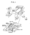
- FIG. l shows an embodiment of the present invention which is applied to an offset press.
- a printed medium to be measured X is placed on a table l and a suitable portion of the printed medium X is magnified and focused through a magnifying lens 2 with an extension tube.
- the magnified light image thus formed is converted by a color video camera 3 into electrical signals which in turn are applied through a superimposer 5 to a color cathode-ray tube 4 which displays an image magnified by tens of times.
- a pattern of the printed medium X to be displayed on the color cathode-ray tube 4 include a pattern which can distinctly indicate the misregistration. For example, it includes registration marks or patterns whose misregistration can be easily recognized.
- the coordinate inputs obtained by the operation of the operation panel 9 in response to the shift of the cursor by the joy stick 8 to the pattern picked up by the camera 3 and displayed on the color cathode-ray tube 4 is calculated by the personal computer 6 and the calculation results; that is, the registration errors are converted into data for correcting the positions of a plate cylinder.
- a flat scanner may be used as input means.
- the register mark on a printed medium may be directly made into contact with an image pickup tube or an image pickup element.
- the register mark is photographed by use of a Polaroid camera and a hard copy thus obtained is placed upon a digitizer to enter the position of the register mark.
- a display device such as a liquid crystal display device or a plasma display device may be used.
- Fig. 2(b), (c) do not have such drawbacks hereinabove.
- Fig. 2(b) shows a status in which registration is incompleted
- Fig. 2(c) shows another status in which the registration is completed, the registration marks being aligned with spacings of 3 millimeters along the circumferential direction. Since deviation of marks in circumferential direction seldom exceeds ⁇ l millimeter, if it is predetermined to align these marks from the above to the below in the order of B, C, M and Y, there should be no change in the order.
- FIGS. 2(a) ⁇ (e) show the images displayed on the screen of the color cathode-ray tube 4 (see FIG. l).
- FIG. 2(a), (b) and (e) show misregistration display marks called register marks and cyan, magenta, yellow and black marks are marked on the gear side and on the operating side of the plate cylinder.
- FIG. 2(d) shows a cross-shaped cursor ll which is superimposed on the patterns or marks shown in FIG. 2(a), (b), (c) or (e). This cursor can be shifted to any position on the screen of the color cathode-ray tube 4 in response to the operation of the joy stick 8.
- FIG. 2(d) shows the point of the patterns upon which the cursor must be registered and there are two kinds of inputs.
- a first kind of input is used to correct in the vertical and horizontal directions of the screen of the color cathode-ray tube 4.
- an operator sets the printed medium on the table l so that the circumferential and lateral directions of the printed medium will not coincide with the coordinates on the screen of the color cathode-ray tube 4.
- a reference line representative of the vertical direction and a reference line representative of the horizontal or lateral direction are marked on the color cathode-ray tube 4 and if the operator sets the printed medium in such a way that one of the color register marks coincides with these reference lines, then the circumferential and lateral directions of the printed medium coincide with the coordinates on the screen of the color cathode-ray tube 4.
- the coordinates are corrected by means of the personal computer. For instance, two points ll3 and ll4 on the vertical or horizontal line of one of the color register marks displayed on the screen of the color cathode-ray tube are entered. If the two points are vertically spaced apart from each other, the "CIR.” button is depressed. On the other hand, when the two points are spaced apart from each other in the horizontal direction, the "LAT.” button is depressed. Then, the vertical and horizontal directions can be automatically corrected.
- a second kind of input is used to designate the coordinates of each of the color register marks.
- the register mark is in the form of a cross so that when the point of intersection between the vertical and horizontal lines is entered as an input, both the vertical and horizontal coordinates are also entered simultaneously.
- register marks with only a vertical or horizontal line.
- the coordinates representative of the direction of a vertical or horizontal line are entered as an input.
- the coordinates of a position are determined in a coordinate system which in turn is determined in response to the corrections in the circumferential and lateral directions.
- only the circumferential or lateral operation is carried out so that the operation panel is provided with a button for operation only in the circumferential direction and a button for operation only in the lateral direction.
- the vertically upward direction of a register mark is always displayed in the vertically upward direction on the screen of the color cathode-ray tube.
- an angle between the vertical of the screen of the color display cathode-ray tube and a line interconnecting between two points selected on the screen of the color cathode-ray tube is less than 45°, it is recognized that the vertical or circumferential input is made and on the other hand, when the angle is greater than 45°, it is recognized that the horizontal or lateral input is made. Therefore one button on the operation panel 9 can have a dual function of the "CIR.” and "LAT.” buttons.
- the register marks are placed substantially at the same position on the upper and lower surfaces of the printing press and must be aligned with each other. Therefore a needle hole is formed adjacent to the register marks and is used to make the inputs of the misregistrations on the upper and lower surface. This can be done by manipulating "NDL" button on the operation panel 9 as in the case of inputting the register mark position coordinate system.
- the upper and lower surfaces can be registered with each other based on the position of the needle hole as a reference.
- the joy stick 8 is operated in such a way that the cursor on the screen of the color cathode-ray tube 4 is sequentially registered with two points on the horizontal or vertical line of a register mark. Thereafter the "CIR.” or "LAT.” button on the operation panel 9 is depressed.
- the joy stick 8 is so operated that the cursor is registered with each of the color registration patterns and then the "MAN” or "GR” button, and the "UP” or “LO” buttons are depressed.
- the joy stick 8 is so operated that the cursor on the display screen of the color cathode-ray tube 4 is aligned with the needle hole formed adjacent to the register marks and then the "NDL" button on the operation panel 9 is depressed.
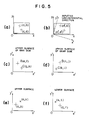
- FIGS. 4 and 5 show the arithmetic operations carried by the personal computer 6 as shown in FIG. l.
- FIG. 4 shows the steps and FIGS. 5(a) ⁇ (f) show the contents of the arithmetic operations.
- the registration error is not computed, but the plate cylinder corrections are directly computed.
- the arithmetic operation steps comprise the depression of the operation button (S-l), the circumferential (lateral) direction correction (S-2), the .display for distinguishing colors (S-3), the coincidence of the coordiantes on the upper and lower surfaces (s-4), the arithmetic operation for obtaining the corrections of the twisted plate cylinder (S-5), and the arithmetic operation for obtaining the correction of the plate cylinder in the circumferential and lateral directions (S-6), and may comprise the application of signals to the motor drive circuit in the registration device of the printing press (S-7).
- the arithmetic operations are carried out by the five steps S-2 -- S-6 so that these steps will be described in detail hereinafter.
- FIG. 5(a) First the coordinates of the position of the register marks which are based on the X- and Y-axes (FIG. 5(a)) are converted into the coordinates based upon the circumferential and lateral direction in response to the circumferential and lateral direction information previously entered (FIG. 5(b)).
- (a, b) and (c, d) are coordinates of the position of the register mark based on the X- and Y-axes on the screen of the color cathode-ray tube and the coordinates (a′, b′) and (c′, d′) shown in FIG. 5(b) are those based on the X′- and Y′-axes with reference to the circumferential direction entered as an input.
- This operation is repeated four times for the gear side, the operation side and their upper and lower surfaces of one printed medium.
- Register marks are displayed on the display 4 according to the converted coordinates along Y axis and are distinguished each other as B (black), C (cyan), M (magenta) and Y (yellow), when the marks of Fig. 2(c) are utilized.
- FIGS. 5(e) and (f) show the conditions of the upper and lower surfaces when the circumferential directions are transformed so as to coincide with the Y′-axis.
- ( , p) and (q, r) are coordinates and * represents a needle hole.
- the origin 0 is shifted to the pin hole (u, v) as shown in FIG. 5(e) and then shifted to the pin hole (s, t) as shown in FIG. 5(f) so that only the X′-axis sign of the register mark is changed.
- ( , p) ⁇ ( -u, p-v) (q, r) ⁇ (s-q, r-t) Then, the register marks on the upper and lower surfaces can be placed on the same coordinates.
- FIGS. 5(c) and (d) show examples of the registration marks on the man and gear sides.
- BL black
- C blue
- [(j-l) ⁇ (f-h)] ⁇ m when the marks of Fig. 2(a) are utilized where m is a constant inherent to a printing press.
- a twist for each color is obtained based on the reference C (blue) and a twisted shift is defined by a value obtained when an average twist is subtracted from the twist of each color.
- the corrections of the plate cylinders in the twisted direction can be obtained from the twisted shift and the magnification.
- the twist varies depending upon the width of a web of paper. Therefore, when the above-stated calculations are made on a web of paper having a standard width in order to obtain a correct twist, an error occurs when the width of a web of paper varies. Therefore, the width can be entered by using ten keys or one of the paper width selection keys is depressed depending on the width of a web of paper used so that the constant m may be varied. A plurality of paper width selection keys are previously provided depending upon the widths of webs of paper to be used.
- the positions of the register marks are represented in the same coordinate system on the upper and lower surfaces of the gear and man sides so that the shifts in the circumferential and lateral directions of the register marks so that they coincide with each other can be obtained by a simple arithmetic operation.
- the shifts are obtained by coinciding all the register marks with an average position in the circumferential, lateral and twist directions, but except the register marks which are extremely deviated, it suffices to obtain an average position. From these shifts and the magnifying power, the corrections of the positions of the plate cylinders in the circumferential and lateral directions can be obtained.
- a mouse instead of the joy stick, a mouse, a track ball, a light pen or digitizer may be used and a menu patch may be marked on the operation panel or a display device.
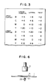
- FIG. 3 shows one output example derived from the printer l2; that is, the results of the arithmetic operations carried out by the personal computer 6.
- the personal computer 6 calculates based upon the magnification of the color pattern, information concerning the positions of the color pattern on the screen of the display device 4 and the information concerning the circumferential (lateral) direction on the screen of the display device 4 so that the registration errors between the respective color patterns can be obtained. It is more preferable that the personal computer is so designed and constructed that it can calculate optimum corrections of the positions of a plate cylinders.
- the printout example as shown in FIG. 3 will be described. This is an example of a printout of an optimum correction of the positions of plate cylinders.
- + represents the operation side in the lateral direction, the forward direction when twisted and the operation side in the circumferential direction while - represents the rearward direction in the circumferential direction and when twisted and the man side in the lateral direction.
- the unit of the numerical values shown is l/l00 mm. Therefore, for instance, BL (black) on the upper surface should be displaced by 5/l00 mm in the forward direction in the circumferential direction, should be displaced by l/l00 mm toward the gear side in the lateral direction and should be twisted by 2/l00 mm in the forward direction.
- References are upper side M (magenta) in the circumferential direction, lower side M (magenta) in the lateral direction and lower side C (cyan) in the twisted direction, which are all determined by the calculations.
- FIG. 6 shows a sheet-fed press to which is applied the present invention.
- the sheet-fed press prints the upper and lower surfaces of a sheet of paper separately so that when the lower surface is to be printed after the upper surface has been printed, it is preferable to utilize the patterns on the upper surface which have been already registered with each other.
- a glass plate 2l is embedded into the table l and a lamp 22 is disposed below the glass plate 2l.
- the light emitted from the lamp 22 is transmitted through a printed medium X and is focused by a lens system 2. Therefore, it becomes possible to observe from the lower surface side the register marks which are registered with each other on the upper surface. As a result, when viewed from the lower surface side, not only the register marks marked on the lower surface but also the register marks marked on the upper surface can be observed. Then it becomes possible to observe how much the deviation of the register marks printed on the lower surface from the register marks on the upper surface is.
- the operation panel ll is provided with an input button for entering the position of the register mark printed on the upper surface of the sheet so that the position of the register mark printed on the upper surface when viewed through the printed medium X is entered and the register mark on the lower surface is aligned with the register mark on the upper surface.
- the input of the coordinate positions of the register marks on the lower surface as well as the input of the circumferential (lateral) direction are substantially similar to that described above with reference to the rotary press. Otherwise a pinhole is provided at the centers of register marks so that the registration is rendered depending upon this pinhole. In this case the optical system shown in FIG. 6 is not needed.
- a combination of a focusing glass and a lens system is used.
- a printed medium X placed on the table l is magnified by an objective lens 33 and a magnifying lens 34, redirected by a mirror 35 and focused on the focusing glass 56.
- the printed medium X is sufficiently illuminated by the light emitted from a lamp 3l and redirected by a half mirror 35.
- the coordinates of the position of each color register mark is entered as an input through a transparent digitizer 37 bonded over the focusing glass 36 and is processed by a special microcomputer (not shown).
- a transparent digitizer 37 bonded over the focusing glass 36 and is processed by a special microcomputer (not shown).
- a conventional digitizer may be used and the digitizer used may be of an optical type, an ultrasonic type or a transparent electrode type.
- FIG. 8 shows a view for explaining a way of setting a camera 3 on a print X to be inspected.
- the print X is set on an inspecting table l00 on which the camera 3 is positioned over a predetermined portion of the print X.
- the camera 3 inputs the image of the registration mark (not shown) printed at the predetermined portion of the print X.
- FIGS. 9A and 9B show views for explaining detailed structure of the camera and its attachments in FIG. 8.
- the camera 3 is supported by a spacer 200 made of a transparent material so that the camera 3 is set on a print X.
- the spacer 200 is transparent, the operator who handles the camera 3 can easily observe whether the registration mark is just under the lense 2 of the camera 3.
- a light emitting end of an optical fiber 40 the other end of which is connected to a light source consisting of a lamp 38, a reflecting mirror 39 and a cooling fan 4l so that the portion under the camera 3 is illuminated by light emitted from one end of the optical fiber 40.
- FIG. 9B shows a view for explaining another way of setting the camera 3 on the print X.
- the camera 3 is supported by a moving mechanism 42 including a pair of side rails and a cross rail which is provided across the side rails.
- the cross rail is movable along a pair of side rails and is immovable when a stopper 43 is locked to fix the cross rail to the side rails.
- the spacer 200 is not needed because the camera 3 is supported by the moving mechanism.
Landscapes
- Inking, Control Or Cleaning Of Printing Machines (AREA)
- Accessory Devices And Overall Control Thereof (AREA)
Applications Claiming Priority (2)
| Application Number | Priority Date | Filing Date | Title |
|---|---|---|---|
| JP60237515A JPS6297846A (ja) | 1985-10-25 | 1985-10-25 | 印刷物の見当誤差量測定方法 |
| JP237515/85 | 1985-10-25 |
Publications (2)
| Publication Number | Publication Date |
|---|---|
| EP0221472A2 true EP0221472A2 (de) | 1987-05-13 |
| EP0221472A3 EP0221472A3 (de) | 1988-08-10 |
Family
ID=17016463
Family Applications (1)
| Application Number | Title | Priority Date | Filing Date |
|---|---|---|---|
| EP86114790A Withdrawn EP0221472A3 (de) | 1985-10-25 | 1986-10-24 | Vorrichtung und Verfahren zur Messung von Registerfehlern bei Druckprodukten |
Country Status (2)
| Country | Link |
|---|---|
| EP (1) | EP0221472A3 (de) |
| JP (1) | JPS6297846A (de) |
Cited By (7)
| Publication number | Priority date | Publication date | Assignee | Title |
|---|---|---|---|---|
| DE3915587C1 (en) * | 1989-05-16 | 1990-11-08 | Man Roland Druckmaschinen Ag, 6050 Offenbach, De | Measurement element for multiple colour offset printing - determines match difference between two partial images independently of quality of image signal |
| WO1991001847A1 (en) * | 1989-07-26 | 1991-02-21 | Tecflex Limited | Optical alignment means |
| EP0401691A3 (de) * | 1989-06-08 | 1991-07-24 | Bobst S.A. | Vorrichtung und Verfahren zum Detektieren von Registermarken in einer Mehrfarbendruckpresse |
| DE4012608A1 (de) * | 1990-04-20 | 1991-10-24 | Roland Man Druckmasch | Verfahren und vorrichtung zur bestimmung von passerdifferenzen an druckbildstellen eines mehrfarbenoffsetdruckes |
| DE4335351A1 (de) * | 1993-10-16 | 1995-04-20 | Heidelberger Druckmasch Ag | Einrichtung zur Kompensation von Passerabweichungen bei Druckprodukten |
| DE4335350A1 (de) * | 1993-10-16 | 1995-04-20 | Heidelberger Druckmasch Ag | Verfahren und Vorrichtung zur Ermittlung von Passerabweichungen bei mehrfarbigen, in einer Druckmaschine erstellten Druckprodukten |
| DE102007031058A1 (de) | 2007-07-04 | 2009-01-08 | Manroland Ag | Verfahren und Vorrichtung zur Applikation von funktionalen Elementen |
Families Citing this family (3)
| Publication number | Priority date | Publication date | Assignee | Title |
|---|---|---|---|---|
| US7193640B2 (en) | 2003-10-31 | 2007-03-20 | Polaroid Corporation | Printer color registration correction |
| JP2011110886A (ja) * | 2009-11-30 | 2011-06-09 | Komori Corp | 印刷機の見当合わせ装置及び印刷機の見当合わせ方法 |
| DE102016204540A1 (de) * | 2016-03-18 | 2017-09-21 | Koenig & Bauer Ag | Inspektionssystem mit einem Bildschirm zur optischen Darstellung eines fotografischen Bildes |
Family Cites Families (5)
| Publication number | Priority date | Publication date | Assignee | Title |
|---|---|---|---|---|
| DE2731842C3 (de) * | 1977-07-14 | 1983-12-22 | Heidelberger Druckmaschinen Ag, 6900 Heidelberg | Verfahren zum Ermitteln von durch Schieben und/oder Dublieren hervorgerufenen Veränderungen im Rastertonwert einer Farbe bedruckter Bogen oder Bahnen |
| DD134743A1 (de) * | 1978-02-13 | 1979-03-21 | Arndt Jentzsch | Passmarkenauswertgeraet an mehrfarbendruckmaschinen |
| DE3136701C1 (de) * | 1981-09-16 | 1983-04-07 | M.A.N.- Roland Druckmaschinen AG, 6050 Offenbach | Vorrichtung zum Abtasten von auf Druckgut aufgedruckten,die Lagegenauigkeit des Druckfarbenauftrages charakterisierender Passmarken |
| DE3136705C1 (de) * | 1981-09-16 | 1982-10-28 | M.A.N.- Roland Druckmaschinen AG, 6050 Offenbach | Verfahren zur Herstellung passgenauer Drucke in Druckmaschinen |
| EP0177885A3 (de) * | 1984-10-03 | 1988-02-24 | Dai Nippon Insatsu Kabushiki Kaisha | Verfahren und Vorrichtung zum Einstellen des Registers in Druckpressen |
-
1985
- 1985-10-25 JP JP60237515A patent/JPS6297846A/ja active Pending
-
1986
- 1986-10-24 EP EP86114790A patent/EP0221472A3/de not_active Withdrawn
Cited By (14)
| Publication number | Priority date | Publication date | Assignee | Title |
|---|---|---|---|---|
| DE3915587C1 (en) * | 1989-05-16 | 1990-11-08 | Man Roland Druckmaschinen Ag, 6050 Offenbach, De | Measurement element for multiple colour offset printing - determines match difference between two partial images independently of quality of image signal |
| AU634241B2 (en) * | 1989-06-08 | 1993-02-18 | Bobst Sa | Procedure and device for detecting printing registration marks in a multi-colour printing press |
| EP0401691A3 (de) * | 1989-06-08 | 1991-07-24 | Bobst S.A. | Vorrichtung und Verfahren zum Detektieren von Registermarken in einer Mehrfarbendruckpresse |
| US5138667A (en) * | 1989-06-08 | 1992-08-11 | Bobst Sa | Process and device for detecting print registration marks on a web from a multi-color printing press |
| WO1991001847A1 (en) * | 1989-07-26 | 1991-02-21 | Tecflex Limited | Optical alignment means |
| DE4012608A1 (de) * | 1990-04-20 | 1991-10-24 | Roland Man Druckmasch | Verfahren und vorrichtung zur bestimmung von passerdifferenzen an druckbildstellen eines mehrfarbenoffsetdruckes |
| US5181257A (en) * | 1990-04-20 | 1993-01-19 | Man Roland Druckmaschinen Ag | Method and apparatus for determining register differences from a multi-color printed image |
| DE4335351A1 (de) * | 1993-10-16 | 1995-04-20 | Heidelberger Druckmasch Ag | Einrichtung zur Kompensation von Passerabweichungen bei Druckprodukten |
| DE4335350A1 (de) * | 1993-10-16 | 1995-04-20 | Heidelberger Druckmasch Ag | Verfahren und Vorrichtung zur Ermittlung von Passerabweichungen bei mehrfarbigen, in einer Druckmaschine erstellten Druckprodukten |
| US5500801A (en) * | 1993-10-16 | 1996-03-19 | Heidelberger Druckmaschinen Ag | Device for compensating for deviations in register in printed products |
| US5696890A (en) * | 1993-10-16 | 1997-12-09 | Heidelberger Druckmaschinen Ag | Method of register regulation and printing control element for determining register deviations in multicolor printing |
| DE4335351C2 (de) * | 1993-10-16 | 2003-04-30 | Heidelberger Druckmasch Ag | Verfahren und Vorrichtung zur Kompensation von Passerabweichungen in einer Offsetrotationsdruckmaschine |
| DE102007031058A1 (de) | 2007-07-04 | 2009-01-08 | Manroland Ag | Verfahren und Vorrichtung zur Applikation von funktionalen Elementen |
| EP2025514A2 (de) | 2007-07-04 | 2009-02-18 | manroland AG | Verfahren und Vorrichtung zur Applikation von funktionalen Elementen |
Also Published As
| Publication number | Publication date |
|---|---|
| EP0221472A3 (de) | 1988-08-10 |
| JPS6297846A (ja) | 1987-05-07 |
Similar Documents
| Publication | Publication Date | Title |
|---|---|---|
| JP2587053B2 (ja) | 多色印刷機における見当合わせ誤差補正方法および装置 | |
| US5056430A (en) | Method of positioning plate cylinders in a multi-color rotary printing machine | |
| JP3053893B2 (ja) | レジスタ偏差検出方法および装置 | |
| DE3924989C2 (de) | ||
| US4963029A (en) | Register-measuring system | |
| EP0177885A2 (de) | Verfahren und Vorrichtung zum Einstellen des Registers in Druckpressen | |
| EP0893254B1 (de) | Verfahren und Vorrichtung zum registergerechten Aufziehen von Druckplatten | |
| EP0221472A2 (de) | Vorrichtung und Verfahren zur Messung von Registerfehlern bei Druckprodukten | |
| EP0277329B1 (de) | Justierverfahren für den Ort einer Farbdichtemessung | |
| JPS6391254A (ja) | 見当修正の方法および装置 | |
| CN87103417A (zh) | 彩色印制中套印误差的确定 | |
| CN101161457B (zh) | 颜色测量头定位装置 | |
| US5649484A (en) | Electronic apparatus and computer-controlled method for alignment correction | |
| JPS6299149A (ja) | 印刷機の自動見当合わせ装置 | |
| JP3735251B2 (ja) | 印刷用見当マークと見当ズレ計測装置 | |
| JPH03175304A (ja) | 記録紙の位置のズレ量測定装置 | |
| JPS6184249A (ja) | 印刷物の見当誤差量測定装置 | |
| JPH0315553A (ja) | 印刷機の版見当検出装置 | |
| JP2002192701A (ja) | ダブリ検出方法、ダブリ検出用マーク、及びダブリ計測装置 | |
| JPH1034893A (ja) | 枚葉印刷機の見当調整装置のための調整量を決定する方法 | |
| JPH0519479B2 (de) | ||
| JP2006345367A (ja) | 画像測定装置及び画像測定方法 | |
| JPS6184250A (ja) | 多色刷印刷機の見当合わせ方法 | |
| JP3356331B2 (ja) | 色合わせ装置 | |
| JP2001018365A (ja) | 色合わせ装置 |
Legal Events
| Date | Code | Title | Description |
|---|---|---|---|
| PUAI | Public reference made under article 153(3) epc to a published international application that has entered the european phase |
Free format text: ORIGINAL CODE: 0009012 |
|
| AK | Designated contracting states |
Kind code of ref document: A2 Designated state(s): CH DE FR GB IT LI SE |
|
| PUAL | Search report despatched |
Free format text: ORIGINAL CODE: 0009013 |
|
| AK | Designated contracting states |
Kind code of ref document: A3 Designated state(s): CH DE FR GB IT LI SE |
|
| 17P | Request for examination filed |
Effective date: 19881015 |
|
| STAA | Information on the status of an ep patent application or granted ep patent |
Free format text: STATUS: THE APPLICATION IS DEEMED TO BE WITHDRAWN |
|
| 18D | Application deemed to be withdrawn |
Effective date: 19900401 |
|
| RIN1 | Information on inventor provided before grant (corrected) |
Inventor name: YAMADA, KENJI Inventor name: SUZUKI, DAIJI Inventor name: KOBAYASHA, MICHIAKI |