EP0224671A2 - Digitaldrehbewegungsdetektor - Google Patents
Digitaldrehbewegungsdetektor Download PDFInfo
- Publication number
- EP0224671A2 EP0224671A2 EP86113338A EP86113338A EP0224671A2 EP 0224671 A2 EP0224671 A2 EP 0224671A2 EP 86113338 A EP86113338 A EP 86113338A EP 86113338 A EP86113338 A EP 86113338A EP 0224671 A2 EP0224671 A2 EP 0224671A2
- Authority
- EP
- European Patent Office
- Prior art keywords
- phase
- frequency
- output
- resolver
- counting means
- Prior art date
- Legal status (The legal status is an assumption and is not a legal conclusion. Google has not performed a legal analysis and makes no representation as to the accuracy of the status listed.)
- Granted
Links
Images


Classifications
-
- G—PHYSICS
- G01—MEASURING; TESTING
- G01P—MEASURING LINEAR OR ANGULAR SPEED, ACCELERATION, DECELERATION, OR SHOCK; INDICATING PRESENCE, ABSENCE, OR DIRECTION, OF MOVEMENT
- G01P3/00—Measuring linear or angular speed; Measuring differences of linear or angular speeds
- G01P3/42—Devices characterised by the use of electric or magnetic means
-
- G—PHYSICS
- G01—MEASURING; TESTING
- G01D—MEASURING NOT SPECIALLY ADAPTED FOR A SPECIFIC VARIABLE; ARRANGEMENTS FOR MEASURING TWO OR MORE VARIABLES NOT COVERED IN A SINGLE OTHER SUBCLASS; TARIFF METERING APPARATUS; MEASURING OR TESTING NOT OTHERWISE PROVIDED FOR
- G01D5/00—Mechanical means for transferring the output of a sensing member; Means for converting the output of a sensing member to another variable where the form or nature of the sensing member does not constrain the means for converting; Transducers not specially adapted for a specific variable
- G01D5/12—Mechanical means for transferring the output of a sensing member; Means for converting the output of a sensing member to another variable where the form or nature of the sensing member does not constrain the means for converting; Transducers not specially adapted for a specific variable using electric or magnetic means
- G01D5/244—Mechanical means for transferring the output of a sensing member; Means for converting the output of a sensing member to another variable where the form or nature of the sensing member does not constrain the means for converting; Transducers not specially adapted for a specific variable using electric or magnetic means influencing characteristics of pulses or pulse trains; generating pulses or pulse trains
- G01D5/247—Mechanical means for transferring the output of a sensing member; Means for converting the output of a sensing member to another variable where the form or nature of the sensing member does not constrain the means for converting; Transducers not specially adapted for a specific variable using electric or magnetic means influencing characteristics of pulses or pulse trains; generating pulses or pulse trains using time shifts of pulses
-
- G—PHYSICS
- G01—MEASURING; TESTING
- G01P—MEASURING LINEAR OR ANGULAR SPEED, ACCELERATION, DECELERATION, OR SHOCK; INDICATING PRESENCE, ABSENCE, OR DIRECTION, OF MOVEMENT
- G01P3/00—Measuring linear or angular speed; Measuring differences of linear or angular speeds
- G01P3/42—Devices characterised by the use of electric or magnetic means
- G01P3/44—Devices characterised by the use of electric or magnetic means for measuring angular speed
- G01P3/48—Devices characterised by the use of electric or magnetic means for measuring angular speed by measuring frequency of generated current or voltage
- G01P3/481—Devices characterised by the use of electric or magnetic means for measuring angular speed by measuring frequency of generated current or voltage of pulse signals
- G01P3/489—Digital circuits therefor
Definitions
- This invention relates to a digital rotation detecting apparatus for detecting a rotation angle and the rotational speed of a rotation body such as a motor.
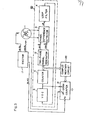
- Fig. 1 is a block diagram of the conventional digital rotation detecting apparatus disclosed in the 546 National Convention of Japanese Institute of Electric Engineers in 1982.
- reference numeral 1 designates a two-phase resolver which rotates in association with a rotary body, such as a motor
- 2 designates a reference oscillator circuit of the fixed frequency having a two-phase output
- 3 designates a phase difference detector for detecting a phase difference between the two-phase output of the reference oscillator circuit 2 and that of the two-phase resolver
- 4 designates a loop filter for proportional-plus-integral-computing the aforesaid phase difference
- 5 designates a voltage control oscillator (to be called the VCO hereinafter) for generating pulses of the frequency corresponding to the output of the loop filter
- 6 designates a counter which counts the output pulse of the VCO
- 7 designates an exciter which generates the two-phase sine-wave output of the phase value corresponding to the counted value by the counter 6 so as
- the problem has been created in that the speed computation executed by the microcomputer and given in the equation (3) of course causes the error.
- the maximum counted value by the counter 6 need only be larger, but it is required therefor either to raise the oscillation frequency of the VCO 5, or to lower the reference oscillation frequency f * , or to perform both the processings.
- the maximum oscillation frequency of VC0 5 has the upper limit, so that it is necessary to lower the reference oscillation frequency f* to obtain a high accuracy for detecting the phase angle ⁇ r ⁇
- the present invention has been designed.
- a first object of the present invention is to provide a digital rotation detecting apparatus which is obtainable of a phase angle at a desired time.
- a second object of the present invention is to provide a digital rotation detecting apparatus which is capable of eliminating a detection delay.
- a third object of the present invention is to provide a digital rotation detecting apparatus which can improve the accuracy for detecting the phase angle ⁇ r while keeping constant the excitation frequency of a resolver without using the low frequency as the excitation frequency of the resolver, in other words, without the need to excite the resolver by the low frequency.
- the digital rotation detecting apparatus of the invention uses a PLL circuit which excites the resolver at the fixed frequency and introduces the resolver output, so that clock pulses of the VC0 in the PLL circuit and those of the double frequency actuate an up-down counter, thereby detecting an instantaneous value of the phase angle of the resolver.
- the digital rotation detecting apparatus of the invention uses the double frequency clock pulses of the excitation frequency and the clock pulses of VCO to thereby detect the phase angle ⁇ r .
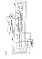
- Fig. 2 is a block diagram of a first embodiment of the digital rotation detecting apparatus of the invention, in which reference numeral 1 designates a two-phase resolver which rotates in association with a rotary body, such as a motor, 3 designates a phase difference detector for detecting a phase difference between a two-phase output of a two-phase signal generator 12 described later and that of the two-phase resolver 1, 4 designates a loop filter for proportional-plus-integral-computing the phase difference, 5 designates a voltage control oscillator (to be called VCO hereinafter) for generating pulses of the frequency corresponding to an output of the loop filter 4, 6 designates a counter for counting the output pulse from the VCO 5, 12 - designates a two-phase signal generator which generates a two-phase AC signal of the phase corresponding to the counted value by the counter 6 as a second counter means, 17 designates an exciter for exciting the resolver 1, and 21 designates an up-down counter as a first counting means which increases or decrease
- the two-phase resolver 1 is excited by the two-phase alternate current of the fixed frequency from the exciter 17.
- the phase of two-phase alternate current is represented by ⁇ o and a phase-angle of the two-phase resolver 1 by ⁇ r
- a two-phase AC signal having a phase of ⁇ o - Or is outputted from the two-phase resolver 1 and fed to the phase difference detector 3.
- the VCO 5 oscillates by the frequency corresponding to the output voltage of the loop filter 4, the oscillation pulses by VCO 5 being counted by the counter 6.
- the two-phase signal generator 12 generates the two-phase AC signal of the phase angle in proportion to the counted value by the counter 6.
- a portion surrounded by the broken line 20 constitutes a PLL (Phase Locked Loop), in which the loop filter 4, which carries out the proportional-plus-integral operation, is automatically controlled to always keep zero the phase angle ⁇ .
- the clock of frequency Nf o is obtained from the exciter 17.
- above-mentioned clock of frequency Nf o is obtained together with the exciting frequency f o from the exciter by constitution thereof including an oscillator of frequency Nf o and a 1/N frequency divider.
- a micro- - processor need to sample the phase angle 8 r at a certain time interval ⁇ T and a difference between the two continuous sampling values need to be divided by ⁇ T.
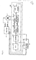
- Fig. 3 of a block diagram thereof the counted value by the counter 6 at the first embodiment shown in Fig. 1 is given to an up-down counter 21 through a complementary circuit 22, so that the up-down counter 21 is adapted to preset a complement to the counted value of the counter 6 through a preset signal generated when the phase angle ⁇ o of the exciter 17 becomes zero.
- the up-down counter 21 is adapted to preset a complement to the counted value of the counter 6 through a preset signal generated when the phase angle ⁇ o of the exciter 17 becomes zero.
- the counted value by counter 6 always indicates N( ⁇ /2 ⁇ )
- the counted value of a frequency-dividing counter in the exciter 17 is usable as the preset data ⁇ o .
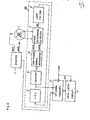
- a block diagram of a third embodiment of the invention is shown.
- the third embodiment is different from the first embodiment shown in Fig. 2 in that the counted value by an up-down counter 21 is adapted to be latched to a data latch circuit 23 by a unit cycle period pulse 24.
- the latch circuit 23 latches the counted value of the up-down counter 21 every time the unit pulse 24 is given, and just thereafter the up-down counter 21 is reset to start new counting.
- the value latched by the data latch circuit 23 at the time when the up-down counter 21 is reset is a rotation angle by which the resolver 1 rotates for the unit time, in turn the rotational speed of the resolver 1.
- the value latched by the data latch circuit 23 is read out to thereby enable the rotational speed of the resolver 1 to be directly detected.
- the third embodiment shown in Fig. 6, however, may be constructed to reset the up-down counter 21 in response to the unit period pulse 24 after the microprocesser reads in the counted value by the up-down counter 21. In this case, there is no need of using the data latch circuit 23.
Landscapes
- Physics & Mathematics (AREA)
- General Physics & Mathematics (AREA)
- Transmission And Conversion Of Sensor Element Output (AREA)
- Measurement Of Length, Angles, Or The Like Using Electric Or Magnetic Means (AREA)
Applications Claiming Priority (2)
| Application Number | Priority Date | Filing Date | Title |
|---|---|---|---|
| JP222256/85 | 1985-10-04 | ||
| JP60222256A JPS6281526A (ja) | 1985-10-04 | 1985-10-04 | デイジタル回転検出器 |
Publications (3)
| Publication Number | Publication Date |
|---|---|
| EP0224671A2 true EP0224671A2 (de) | 1987-06-10 |
| EP0224671A3 EP0224671A3 (en) | 1988-10-19 |
| EP0224671B1 EP0224671B1 (de) | 1991-12-04 |
Family
ID=16779540
Family Applications (1)
| Application Number | Title | Priority Date | Filing Date |
|---|---|---|---|
| EP86113338A Expired - Lifetime EP0224671B1 (de) | 1985-10-04 | 1986-09-27 | Digitaldrehbewegungsdetektor |
Country Status (9)
| Country | Link |
|---|---|
| US (1) | US4734655A (de) |
| EP (1) | EP0224671B1 (de) |
| JP (1) | JPS6281526A (de) |
| KR (1) | KR900002114B1 (de) |
| AU (1) | AU571792B2 (de) |
| BR (1) | BR8604820A (de) |
| CA (1) | CA1270046A (de) |
| DE (1) | DE3682751D1 (de) |
| SU (1) | SU1662360A3 (de) |
Families Citing this family (7)
| Publication number | Priority date | Publication date | Assignee | Title |
|---|---|---|---|---|
| US5140245A (en) * | 1990-09-24 | 1992-08-18 | Westinghouse Electric Corp. | Pmg-based position sensor and synchronous drive incorporating same |
| EP0735691A3 (de) * | 1995-03-31 | 1998-04-29 | Siemens Aktiengesellschaft | Phasenregelungsschaltung für Resolvererregung bei digitalen Steuerungen |
| KR20000045995A (ko) * | 1998-12-31 | 2000-07-25 | 추호석 | 타코메타의 속도측정방법 |
| JP3621335B2 (ja) * | 2000-09-05 | 2005-02-16 | アルプス電気株式会社 | 回転角速度検出装置及び回転角速度検出方法、並びにこの装置を使用した自動車 |
| US6989697B2 (en) * | 2004-01-15 | 2006-01-24 | Organicid, Inc. | Non-quasistatic phase lock loop frequency divider circuit |
| US20070159119A1 (en) * | 2006-01-10 | 2007-07-12 | Caterpillar Inc. | Power system |
| DE102022102337A1 (de) | 2022-02-01 | 2023-08-03 | Infineon Technologies Ag | Winkelsensorvorrichtung und Verfahren |
Family Cites Families (6)
| Publication number | Priority date | Publication date | Assignee | Title |
|---|---|---|---|---|
| US3564368A (en) * | 1968-01-10 | 1971-02-16 | Gen Electric | Spindle speed control monitor |
| US3828234A (en) * | 1973-05-14 | 1974-08-06 | Rca Corp | Motor speed control system |
| GB1527741A (en) * | 1975-03-25 | 1978-10-11 | Rca Corp | Brushless dc motor rotation control |
| US4355305A (en) * | 1980-04-24 | 1982-10-19 | The Bendix Corporation | Resolver processor with error detection |
| JPS58127294A (ja) * | 1982-01-26 | 1983-07-29 | 株式会社東芝 | デイジタル移動検出装置 |
| JPS60187864A (ja) * | 1984-03-08 | 1985-09-25 | Sanyo Denki Kk | レゾルバを用いた回転速度及び回転位置検出装置 |
-
1985
- 1985-10-04 JP JP60222256A patent/JPS6281526A/ja active Granted
-
1986
- 1986-02-25 KR KR1019860001317A patent/KR900002114B1/ko not_active Expired
- 1986-09-03 US US06/903,296 patent/US4734655A/en not_active Expired - Lifetime
- 1986-09-05 AU AU62502/86A patent/AU571792B2/en not_active Ceased
- 1986-09-27 DE DE8686113338T patent/DE3682751D1/de not_active Expired - Lifetime
- 1986-09-27 EP EP86113338A patent/EP0224671B1/de not_active Expired - Lifetime
- 1986-10-03 BR BR8604820A patent/BR8604820A/pt not_active IP Right Cessation
- 1986-10-03 SU SU864028241A patent/SU1662360A3/ru active
- 1986-10-03 CA CA000519792A patent/CA1270046A/en not_active Expired - Lifetime
Also Published As
| Publication number | Publication date |
|---|---|
| AU571792B2 (en) | 1988-04-21 |
| JPS6281526A (ja) | 1987-04-15 |
| KR900002114B1 (ko) | 1990-04-02 |
| US4734655A (en) | 1988-03-29 |
| EP0224671A3 (en) | 1988-10-19 |
| AU6250286A (en) | 1987-04-30 |
| KR870004307A (ko) | 1987-05-08 |
| SU1662360A3 (ru) | 1991-07-07 |
| EP0224671B1 (de) | 1991-12-04 |
| JPH0438291B2 (de) | 1992-06-24 |
| DE3682751D1 (de) | 1992-01-16 |
| CA1270046A (en) | 1990-06-05 |
| BR8604820A (pt) | 1987-07-07 |
Similar Documents
| Publication | Publication Date | Title |
|---|---|---|
| US5886486A (en) | Sensorless brushless DC motor | |
| EP0637138A1 (de) | Lockdetektorschaltung | |
| US4475105A (en) | System for detecting mechanical movement | |
| GB2081997A (en) | System for converting mechanical movement to digital signal | |
| KR840003362A (ko) | 디지탈 이동 검출 장치 | |
| US4734655A (en) | Digital rotation detecting apparatus | |
| US6107763A (en) | Closed loop and open synchronization of the phase switchings in driving a DC motor | |
| KR910003518B1 (ko) | 싱크로 전기기계를 이용한 회전검출장치 | |
| EP0120692B1 (de) | Phasenmodulationstyp-Digitalpositionsdetektor | |
| JP2531269B2 (ja) | 同期検出方式 | |
| US5130626A (en) | Device for controlling rotational speed of motor | |
| JPH0781879B2 (ja) | 回転検出装置 | |
| EP2110644B1 (de) | Phasendifferenzdetektor und drehpositionsdetektor | |
| JPS63229320A (ja) | 回転検出装置 | |
| JPH0230726Y2 (de) | ||
| JPH0693629B2 (ja) | ドリフト検出機能付位相同期回路 | |
| JPS6310469B2 (de) | ||
| KR890007454Y1 (ko) | 교류서보 모터의 위상검파 회로 | |
| JPS63124623A (ja) | Pll周波数シンセサイザのアンロツク検出回路 | |
| JPH0236090Y2 (de) | ||
| JPH0419512A (ja) | 回転角度検出装置 | |
| JPH0679031B2 (ja) | 回転方向判別装置 | |
| JPS60194776A (ja) | 回転電機の速度制御装置 | |
| JPH05346434A (ja) | レゾルバの駆動制御装置 | |
| JPS6280559A (ja) | 速度検出装置 |
Legal Events
| Date | Code | Title | Description |
|---|---|---|---|
| PUAI | Public reference made under article 153(3) epc to a published international application that has entered the european phase |
Free format text: ORIGINAL CODE: 0009012 |
|
| AK | Designated contracting states |
Kind code of ref document: A2 Designated state(s): CH DE FR GB LI SE |
|
| PUAL | Search report despatched |
Free format text: ORIGINAL CODE: 0009013 |
|
| AK | Designated contracting states |
Kind code of ref document: A3 Designated state(s): CH DE FR GB LI SE |
|
| 17P | Request for examination filed |
Effective date: 19881213 |
|
| 17Q | First examination report despatched |
Effective date: 19900323 |
|
| GRAA | (expected) grant |
Free format text: ORIGINAL CODE: 0009210 |
|
| AK | Designated contracting states |
Kind code of ref document: B1 Designated state(s): CH DE FR GB LI SE |
|
| REF | Corresponds to: |
Ref document number: 3682751 Country of ref document: DE Date of ref document: 19920116 |
|
| ET | Fr: translation filed | ||
| PLBE | No opposition filed within time limit |
Free format text: ORIGINAL CODE: 0009261 |
|
| STAA | Information on the status of an ep patent application or granted ep patent |
Free format text: STATUS: NO OPPOSITION FILED WITHIN TIME LIMIT |
|
| 26N | No opposition filed | ||
| EAL | Se: european patent in force in sweden |
Ref document number: 86113338.7 |
|
| REG | Reference to a national code |
Ref country code: GB Ref legal event code: 746 Effective date: 19960611 |
|
| REG | Reference to a national code |
Ref country code: FR Ref legal event code: D6 |
|
| PGFP | Annual fee paid to national office [announced via postgrant information from national office to epo] |
Ref country code: FR Payment date: 19980909 Year of fee payment: 13 |
|
| PGFP | Annual fee paid to national office [announced via postgrant information from national office to epo] |
Ref country code: GB Payment date: 19981001 Year of fee payment: 13 |
|
| PG25 | Lapsed in a contracting state [announced via postgrant information from national office to epo] |
Ref country code: GB Free format text: LAPSE BECAUSE OF NON-PAYMENT OF DUE FEES Effective date: 19990927 |
|
| GBPC | Gb: european patent ceased through non-payment of renewal fee |
Effective date: 19990927 |
|
| PG25 | Lapsed in a contracting state [announced via postgrant information from national office to epo] |
Ref country code: FR Free format text: LAPSE BECAUSE OF NON-PAYMENT OF DUE FEES Effective date: 20000531 |
|
| REG | Reference to a national code |
Ref country code: FR Ref legal event code: ST |
|
| REG | Reference to a national code |
Ref country code: CH Ref legal event code: PUE Owner name: TOSHIBA MITSUBISHI-ELECTRIC INDUSTRIAL SYSTEMS CO Free format text: MITSUBISHI DENKI KABUSHIKI KAISHA#2-3, MARUNOUCHI 2-CHOME#CHIYODA-KU/TOKYO (JP) -TRANSFER TO- TOSHIBA MITSUBISHI-ELECTRIC INDUSTRIAL SYSTEMS CORPORATION#13-16, MITA 3-CHOME, MINATO-KU#TOKYO (JP) Ref country code: CH Ref legal event code: NV Representative=s name: BOVARD AG PATENTANWAELTE |
|
| PGFP | Annual fee paid to national office [announced via postgrant information from national office to epo] |
Ref country code: SE Payment date: 20050906 Year of fee payment: 20 |
|
| PGFP | Annual fee paid to national office [announced via postgrant information from national office to epo] |
Ref country code: DE Payment date: 20050922 Year of fee payment: 20 |
|
| PGFP | Annual fee paid to national office [announced via postgrant information from national office to epo] |
Ref country code: CH Payment date: 20050928 Year of fee payment: 20 |
|
| REG | Reference to a national code |
Ref country code: CH Ref legal event code: PL |
|
| EUG | Se: european patent has lapsed |