EP0232009B1 - Direction assistée et dispositif de commande pour direction assistée avec détection de l'angle de rotation du volant - Google Patents
Direction assistée et dispositif de commande pour direction assistée avec détection de l'angle de rotation du volant Download PDFInfo
- Publication number
- EP0232009B1 EP0232009B1 EP87300145A EP87300145A EP0232009B1 EP 0232009 B1 EP0232009 B1 EP 0232009B1 EP 87300145 A EP87300145 A EP 87300145A EP 87300145 A EP87300145 A EP 87300145A EP 0232009 B1 EP0232009 B1 EP 0232009B1
- Authority
- EP
- European Patent Office
- Prior art keywords
- steering
- steering wheel
- control system
- counter
- control
- Prior art date
- Legal status (The legal status is an assumption and is not a legal conclusion. Google has not performed a legal analysis and makes no representation as to the accuracy of the status listed.)
- Expired
Links
- 238000001514 detection method Methods 0.000 title description 5
- 230000007935 neutral effect Effects 0.000 description 20
- 238000000034 method Methods 0.000 description 13
- 230000008569 process Effects 0.000 description 12
- 230000007246 mechanism Effects 0.000 description 2
- 230000001133 acceleration Effects 0.000 description 1
- 238000009825 accumulation Methods 0.000 description 1
- 230000008859 change Effects 0.000 description 1
- 230000007423 decrease Effects 0.000 description 1
- 238000010586 diagram Methods 0.000 description 1
- 230000006870 function Effects 0.000 description 1
- 230000009467 reduction Effects 0.000 description 1
- 239000010913 used oil Substances 0.000 description 1
Images

Classifications
-
- B—PERFORMING OPERATIONS; TRANSPORTING
- B62—LAND VEHICLES FOR TRAVELLING OTHERWISE THAN ON RAILS
- B62D—MOTOR VEHICLES; TRAILERS
- B62D5/00—Power-assisted or power-driven steering
- B62D5/06—Power-assisted or power-driven steering fluid, i.e. using a pressurised fluid for most or all the force required for steering a vehicle
-
- B—PERFORMING OPERATIONS; TRANSPORTING
- B62—LAND VEHICLES FOR TRAVELLING OTHERWISE THAN ON RAILS
- B62D—MOTOR VEHICLES; TRAILERS
- B62D15/00—Steering not otherwise provided for
- B62D15/02—Steering position indicators ; Steering position determination; Steering aids
- B62D15/021—Determination of steering angle
- B62D15/0245—Means or methods for determination of the central position of the steering system, e.g. straight ahead position
-
- B—PERFORMING OPERATIONS; TRANSPORTING
- B62—LAND VEHICLES FOR TRAVELLING OTHERWISE THAN ON RAILS
- B62D—MOTOR VEHICLES; TRAILERS
- B62D5/00—Power-assisted or power-driven steering
- B62D5/04—Power-assisted or power-driven steering electrical, e.g. using an electric servo-motor connected to, or forming part of, the steering gear
-
- B—PERFORMING OPERATIONS; TRANSPORTING
- B62—LAND VEHICLES FOR TRAVELLING OTHERWISE THAN ON RAILS
- B62D—MOTOR VEHICLES; TRAILERS
- B62D6/00—Arrangements for automatically controlling steering depending on driving conditions sensed and responded to, e.g. control circuits
Definitions
- the present invention relates to a power steering apparatus and to a control system for a power steering apparatus having a detection device for detecting the angular rotation of a steering wheel, and more particularly to a control system for controlling an automobile electric power steering apparatus.
- EP-A 0 190 678 discloses an electric power steering apparatus in which a torque sensor detects a steering force exerted to a steering wheel, a motor controlled in accordance with the output of the torque sensor and an acceleration/deceleration deciding circuit for reviewing the outputs of the torque sensor and deciding whether the steering wheel is king accelerated or decelerated. In dependence upon such a consideration so a steering assisting force to the steering wheel is applied.
- the electric power steering apparatus also uses the angular rotation of the steering wheel, hereinafter referred to as steering wheel angle, as one of its parameters.
- steering wheel angle angular rotation of the steering wheel
- JP-A 58 202 803 discloses an analog control type electric power steering system which uses an encoder which utilises a slidable variable resistor linked to a steering wheel in order to detect the steering wheel angle.
- the prior art slidable variable resistor is subject to problems of sliding noise, shift of reference due to temperature change and life time, and sufficiently high reliability is hard to attain.
- a control system for a power steering apparatus including a steering angle sensor means arranged to detect each revolution of a steering wheel from a predetermined datum including at said datum and to produce an output signal indicative thereof, said steering angle sensor means also being arranged to detect discrete angular positions of said steering wheel during each revolution thereof and to produce a signal indicative of each said angular position; a counter means for counting the signals indicative of each angular position; characterised by vehicle velocity determination means; resetting means for said counter means, said resetting means being adapted to reset the counter means when the vehicle velocity determination means indicates a velocity above a predetermined value and said steering angle sensor means produces an output signal indicative of said predetermined datum; and control means for effecting power steering control by utilising the count of said counter means as a parameter.
- reference pulses are generated at a plurality of steering wheel angle positions including a neutral position (straight ahead position of a vehicle) of the steering wheel, and angle pulses are generated by rotation angle sensor as the steering wheel is rotated.
- the reference pulses detected when a vehicle speed is higher than a predetermined speed is used as a reference angle position pulse and the angle pulses are counted up or down with respect to the reference angle position pulse to detect the steering angle to thereby provide a more accurate determination of the steering wheel position than hitherto.
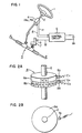
- Fig. 1 shows a conventional electric power steering apparatus which uses a power assisting motor in a rack-and-pinion type steering system.
- a steering force (steering torque) Y applied by a driver to a rack-pinion mechanism 3 from a steering wheel 1 through a steering shaft 2 is detectded by a torque sensor 4a in a sensor unit 4.
- the detected signal is supplied to a control circuit 5 which in turn supplies a corresponding control signal M to a motor 6.
- the motor 6 applies an additional force to the rack-pinion mechanism 3 through a reduction gear 7 so that the steering force Y is reduced.
- a steering angle sensor 4b for detecting the angular rotation of the steering shaft 2 is provided in the sensor unit 4.
- the angular rotation of the steering wheel from a neutral position of the steering wheel is detected and the sensor unit 4 produces a corresponding output signal E so that appropriate restoring force control for the steering wheel is carried out.
- Figs. 2A and 2B show one form of the steering angle sensor 4b used in the control system of the present invention.
- the sensor 4b comprises two disks 8a and 8b each having magnetic N-poles and S-poles magnetised on its periphery, and magnetic detection heads 8c and 8d such as magneto-restrictive elements arranged near the periphery.
- the disk 8a has only one pair of N and S poles arranged on the periphery, while disk 8b has N and S poles alternately magnetised on its periphery.
- the head 8c produces only one pulse per revolution at a predetermined angular position.
- the head 8c produces a plurality of pulses (called reference pulses Ez).
- One of these Ez pulses corresponds to the neutral or straight ahead position N of the steering wheel.
- the disk 8b has 600 pairs of N-poles and S-poles arranged on the periphery thereof.
- the head 8d produces one pulse for each 0.6 degree of rotation of the steering wheel 1.
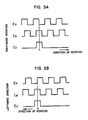
- the head 8d has two detectors which are spaced from each other by 1/4 pitch along the periphery of the disk 8b. Accordingly, two pulses (angle pulses E A and Ee) having a phase difference of 90 degrees therebtween are generated as the disk 8b rotates.
- the head 8d When the steering wheel is rotated rightward (clockwise), the head 8d detects the angle pulses E A and Ee as shown in Fig. 3A, and when it is rotated counter clockwise, the head 8d detects the pulses as shown in Fig. 3B.
- the sensor shown in Figs. 2A and 2B is called a rotary encoder.
- the periphery of the disk 8B is provided with a plurality of holes corresponding in number to the magnetic poles and the holes may be detected by photo-couplers to produce the required pulse signals.
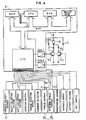
- Fig. 4 shows an embodiment of the control circuit 5 constructed utilising a microcomputer.
- a CPU which is the heart of the control circuit reads various data including the pulses Ez, E A , E B from the steering angle sensor 4b, a torque signal , from a torque sensor 4C and a vehicle velocity signal from a vehicle velocity sensor 10, through I/O, processes them together with data stored in a ROM and a RAM, supplies control signals to transistors Tr1 and Tr2 in a control circuit of motor 6 through amplifiers Amp1 and Amp2 to apply an assisting steering force and a steering angle controlling steering force to the motor 6.
- An apparatus for generating such control signals is known, for example, by U.S.P. 4,476,529.
- the motor 6 has two field coils F ! and F @ .
- the motor 6 is rotated by turning on only one of the transistors Tr1 and Tr2, the direction of rotation being controlled by which of the transistors Tr1 and Tr2 is selected to be turned on.
- A denotes an armature and D denotes a flywheel diode.
- the steering angle sensor 4B generates 600 pulses E A and Es per revolution of the steering handle. Assuming that three revolutions are required to rotate the steering wheel in the present embodiment from the left to the right limit, 1800 pulses E A and 1800 pulses E B are generated in the three revolutions.
- an up/down counter which can count from +900 to -900 is used as a steering angle counter.
- a positive count represents a rightward (clockwise) steering angle and a negative count represents a leftward (counter clockwise) steering angle.
- the steering angle is zero, that is, at the neutral position N, the count of the counter is zero.
- the up/down counter is a software counter and the count is stored in a Random Excess Memory (RAM). Accordingly, when an ignition key of the ve- hiclew is turned to its off position, the count of the counter is cleared, and when the ignition key is turned to its on position, the count is reset to zero.
- RAM Random Excess Memory
- the pulses E A and E B are not counted until the steering angle reaches the neutral position, when the counting of the pulses is started.
- the count of the counter represents the steering angle
- the restoring force control in the power steering system is disclosed in U.S.P. 4,476,529
- the power assisting force control in accordance with the vehicle velocity or the actuator inertia compensation control as disclosed in JP-A-60-193765 is carried out based on the detected steering angle.
- the power assisting control to reduce the steering force of the steering wheel is carried out in a known method at the time of starting the engine independently from the steering angle.
- the physical position of the steering angle sensor 4b relative to the steering shaft 2 is appropriately selected such that the reference pulse Ez is generated when the steering angle actually reaches the neutral position.
- the counting of the angle pulses is started at the point of generation of the pulse Ez.
- the reference pulse Ez is generated a plurality of times, for example, three times in the present embodiment, in the variable range of the steering angle from lock to lock.
- the reference pulse is generated at the neutral position but it is also generated when the steering angle is not at the neutral position. Accordingly, the neutral position cannot be detected only by the generation of the reference pulse.
- the reference pulse is generated when the velocity of the vehicle whose steering angle is to be detected is higher than a predetermined velocity, it is assumed that the steering angle is at the neutral position to discriminate the reference pulse generated at the neutral position from the reference pulses generated at other positions. The reason therefor is explained below.
- the reference pulse Ez is generated at a plurality of steering angle positions in the variable range of the steering angle. Assuming that the reference pulse Ez is generated three times in the variable range of the steering angle, the steering angles at which the reference pulses are generated at other than the neutral position must be very large, either leftward or rightward, and it will be practically impossible to drive the vehicle at such a large steering angle if the vehicle velocity is higher than a predetermined velocity.
- the true neutral position can be detected by using the reference pulse detected when the vehicle velocity is higher than the predetermined velocity.
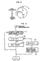
- a step S1 a check is made to determine whether or not the vehicle velocity has reached a predetermined velocity, 40Km/h in the present embodiment. If the decision is NO, no further processing is required and the process is terminated.
- the vehicle velocity may be detected by using the pulse train from the velocity sensor 10 shown in Fig. 4.
- step S1 If the decision in the step S1 is YES, the process proceeds to step S2 where a flag N (neutral flag) in the RAM is checked.
- step S2 If the decision in the step S2 is YES, that is, if the flag N has been set, the process proceeds to step S3 where the up/down counter is reset. Then, the process starts again.
- step S2 determines whether the decision in the step S2 is NO, that is, if the flag N has not yet been set. If the decision in the step S2 is NO, that is, if the flag N has not yet been set, the process proceeds to step S4 where the flag N is set to start the up/down counter. In step S5, a flag R for instructing the execution of the steering angle control is set. Then, the process begins again.
- Fig. 7 shows a process which is carried out each time the angle pulse E B is switched from HIGH to LOW.
- step S6 a check is made to determine whether or not the flag N has been set. If the decision is NO, that is, if the flag N has not yet been set, the process starts again.
- step S6 If the decision in the step S6 is YES, that is, if the flag N has been set, the direction of rotation is checked in step S7. Since the check is carried out at the occurrence of the angle pulse E B shown in Figs. 3A and 3B, a check to determine whether or not the angle pulse E A is LOW is made at the occurrence of the angle phase E B in the step S7. If the angle pulse is LOW, the angle pulses E A and E B are in the relationship shown in Fig. 3A and the steering wheel has been rotated in the rightward direction. If E A is HIGH in the step S7, the angle pulses E A and E B are in the relationship shown in Fig. 3B and the steering wheel has been rotated in the leftward direction.
- step S7 if the decision in step S7 is YES, that is, rightward rotation, the steering angle up/down counter is incremented by one in step S8 and if the decision is NO, that is, leftward rotation, the up/down counter is decremented by one in step S9. Then, the process begins again.
- the steering angle that is, the angle representing the deviation from the straight direction (neutral position) of the steering wheels of the vehicle is detected by the content of the up/down counter in the control circuit 5.
- Fig. 8 shows a process which is carried out at a predetermined time interval by timer interruption.
- step S10 a flag R is checked, and if the flag R has been set, the steering angle control is carried out in a step S11 in accordance with the count of the up/down counter in a known manner.
- the setting of the flag N is prevented until the vehicle velocity reaches the predetermined velocity in step S1.
- the counting of the angle pulse E B is prevented until the flag N is set in step S6.
- the flag N is set in step S4 if the vehicle velocity is higher than the predetermined velocity (40 Km/h), and the counting of the angle pulses is enabled.
- counting is started from the true neutral position of the steering wheel so that the exact steering angle is detected by the steering angle sensor 4b.
- the counter is reset in step S3 so that accumulation of error count due to noise is prevented.
- the counter counts the angle pulses which represent the steering angle by the process of Fig. 7. If error signals caused by noise are counted, the error signals appear as an error of the steering angle and such an error may be accumulated each time the error count appears.
- the decision in the step S1 is YES, the steering angle is at the neutral position and the count of the counter should be zero. If it is not zero, it means that the error is included. Since the counter is reset in step S3, the error is always corrected and the correct steering angle is detected.
- step S5 of Fig. 6 is provided.
- the flag R is set.
- the steering wheel angle control such as restoring force control is started after the steering angle detection is enabled.
- the power assist force may also be in accordance with one of the vehicle velocity and actuator inertia compensation control in the power assist control mode. Thus, proper steering angle control is always attained.
Landscapes
- Engineering & Computer Science (AREA)
- Chemical & Material Sciences (AREA)
- Combustion & Propulsion (AREA)
- Transportation (AREA)
- Mechanical Engineering (AREA)
- Steering Control In Accordance With Driving Conditions (AREA)
- Power Steering Mechanism (AREA)
- Length Measuring Devices With Unspecified Measuring Means (AREA)
- Measurement Of Length, Angles, Or The Like Using Electric Or Magnetic Means (AREA)
Claims (11)
Applications Claiming Priority (2)
| Application Number | Priority Date | Filing Date | Title |
|---|---|---|---|
| JP644/86 | 1986-01-08 | ||
| JP64486A JPH0665550B2 (ja) | 1986-01-08 | 1986-01-08 | パワ−ステアリング制御装置 |
Publications (2)
| Publication Number | Publication Date |
|---|---|
| EP0232009A1 EP0232009A1 (fr) | 1987-08-12 |
| EP0232009B1 true EP0232009B1 (fr) | 1989-10-11 |
Family
ID=11479410
Family Applications (1)
| Application Number | Title | Priority Date | Filing Date |
|---|---|---|---|
| EP87300145A Expired EP0232009B1 (fr) | 1986-01-08 | 1987-01-08 | Direction assistée et dispositif de commande pour direction assistée avec détection de l'angle de rotation du volant |
Country Status (5)
| Country | Link |
|---|---|
| US (1) | US4803629A (fr) |
| EP (1) | EP0232009B1 (fr) |
| JP (1) | JPH0665550B2 (fr) |
| KR (1) | KR890003748B1 (fr) |
| DE (1) | DE3760720D1 (fr) |
Families Citing this family (48)
| Publication number | Priority date | Publication date | Assignee | Title |
|---|---|---|---|---|
| JPH0612488B2 (ja) * | 1986-01-14 | 1994-02-16 | 株式会社小糸製作所 | 車両用コーナリングランプシステム |
| GB2202501B (en) * | 1987-03-24 | 1991-08-21 | Honda Motor Co Ltd | Electric power steering system for vehicles |
| JPS63197710U (fr) * | 1987-06-12 | 1988-12-20 | ||
| DE68911775T2 (de) * | 1988-07-11 | 1994-06-23 | Koyo Seiko Co | Einrichtung zur Ermittlung des Mittelpunktes des Lenkungswinkels. |
| US5040109A (en) * | 1988-07-20 | 1991-08-13 | Digital Equipment Corporation | Efficient protocol for communicating between asychronous devices |
| JPH07100446B2 (ja) * | 1988-09-16 | 1995-11-01 | 日産自動車株式会社 | 車両用中立操舵角検出装置 |
| JPH07108665B2 (ja) * | 1988-11-14 | 1995-11-22 | 自動車機器株式会社 | 動力舵取装置の制御方法 |
| US5019981A (en) * | 1989-03-09 | 1991-05-28 | Fuji Jukogyo Kabushiki Kaisha | Device and method for decreasing power consumption of a steering angle detecting system for vehicle |
| JPH02248811A (ja) * | 1989-03-22 | 1990-10-04 | Fuji Heavy Ind Ltd | 車両用舵角センサの絶対舵角検出方法 |
| US5203420A (en) * | 1989-04-25 | 1993-04-20 | Nissan Motor Co., Ltd. | Auxiliary steering mechanism for automotive vehicles |
| DE3920853A1 (de) * | 1989-06-24 | 1991-01-10 | Bosch Gmbh Robert | Vorrichtung zur einstellung des steuerwinkels von fahrzeugraedern |
| JP2951336B2 (ja) * | 1989-06-28 | 1999-09-20 | 本田技研工業株式会社 | 舵角検出装置 |
| JPH0361170A (ja) * | 1989-07-28 | 1991-03-15 | Fuji Heavy Ind Ltd | 自動車用電動式パワステアリング装置の故障判定装置 |
| US5032999A (en) * | 1989-11-01 | 1991-07-16 | Yale Materials Handling Corporation | Motion sensor useful for power assisted steering systems |
| US4999776A (en) * | 1989-11-30 | 1991-03-12 | Ford Motor Company | Method and apparatus for determining the center position of a vehicular steering system |
| JP2949765B2 (ja) * | 1990-04-12 | 1999-09-20 | 日産自動車株式会社 | 車載装備品の姿勢制御装置 |
| JP2519650Y2 (ja) * | 1990-04-27 | 1996-12-11 | 自動車機器株式会社 | 電動式動力舵取装置 |
| US5198981A (en) * | 1990-10-09 | 1993-03-30 | General Motors Corporation | Closed-loop torque control for electric power steering |
| DE4104902A1 (de) * | 1991-02-18 | 1992-08-20 | Swf Auto Electric Gmbh | Verfahren und anordnung zur erkennung einer bewegungsrichtung, insbesondere einer drehrichtung |
| US5201380A (en) * | 1991-07-10 | 1993-04-13 | Trw Inc. | Phased redundant sensor steering control |
| JP2768106B2 (ja) * | 1992-01-28 | 1998-06-25 | 三菱自動車工業株式会社 | 液圧パワーステアリング用圧力センサの零圧値補正方法 |
| JPH066165U (ja) * | 1992-07-01 | 1994-01-25 | 東洋運搬機株式会社 | 電気式パワーステアリングアクチュエータ |
| US5491632A (en) * | 1994-05-26 | 1996-02-13 | General Motors Corporation | Rotary encoder with neutral position |
| US5434784A (en) * | 1994-08-26 | 1995-07-18 | General Motors Corporation | Vehicle steering wheel position sensing apparatus |
| US5568048A (en) * | 1994-12-14 | 1996-10-22 | General Motors Corporation | Three sensor rotational position and displacement detection apparatus with common mode noise rejection |
| US5732372A (en) * | 1995-06-09 | 1998-03-24 | Ford Global Technologies, Inc. | Method for determining a center position of a vehicle steering system |
| US6032755A (en) * | 1996-01-30 | 2000-03-07 | Trw Inc. | Method and apparatus for compensating torque steer |
| US5787375A (en) * | 1996-04-01 | 1998-07-28 | Ford Global Technologies, Inc. | Method for determining steering position of automotive steering mechanism |
| US5790966A (en) * | 1996-04-01 | 1998-08-04 | Ford Global Technologies, Inc. | Method for determining steering position of automotive steering mechanism |
| DE19714786C1 (de) * | 1997-04-10 | 1998-10-22 | Danfoss As | Lenkeinrichtung |
| US6089344A (en) * | 1998-06-01 | 2000-07-18 | Ford Global Technologies, Inc. | Method and apparatus for determining the center position of a steering system |
| US6364050B1 (en) * | 1999-01-15 | 2002-04-02 | Trw Lucas Varity Electric Steering Ltd. | Electrical power assisted steering assemblies |
| GB9902438D0 (en) * | 1999-02-05 | 1999-03-24 | Trw Lucas Varity Electric | Improvements relating to electric power assisted steering assemblies |
| KR100336471B1 (ko) * | 2000-04-19 | 2002-05-15 | 밍 루 | 자동차용 전자식 조향장치의 회전토오크 감지구조 |
| US6721639B2 (en) * | 2001-12-20 | 2004-04-13 | Delphi Technologies, Inc. | Hi-resolution digital steering sensor fault detection |
| US6789017B2 (en) | 2002-02-15 | 2004-09-07 | Robert Bosch Corporation | Vehicle steering angle position determination method |
| US6816799B2 (en) * | 2002-08-05 | 2004-11-09 | Robert Bosch Corporation | Vehicle operating parameter determination system and method |
| US6868934B2 (en) * | 2003-07-09 | 2005-03-22 | Honda Giken Kogyo Kabushiki Kaisha | Variable power steering assist using driver grip pressure |
| TWM246600U (en) * | 2003-12-31 | 2004-10-11 | Taigene Metal Industry Co Ltd | Magnetic sensor |
| EP1677079A1 (fr) * | 2004-12-30 | 2006-07-05 | Taigene Metal Industry Co., Ltd. | Capteur magnétique |
| US7196527B2 (en) * | 2004-02-17 | 2007-03-27 | Stridsberg Innovation Ab | Redundant compact encoders |
| US7562591B2 (en) * | 2006-06-26 | 2009-07-21 | KRS Technologies Co. | Steering angle sensor |
| US8000860B2 (en) * | 2007-04-04 | 2011-08-16 | Chung Shan Institute Of Science And Technology, Armaments Bureau, M.N.D. | Steering angle sensor |
| US9964457B2 (en) * | 2015-07-20 | 2018-05-08 | Honda Motor Co., Ltd. | Rotary force diagnostic tools and methods |
| US10041846B2 (en) | 2015-07-20 | 2018-08-07 | Honda Motor Co., Ltd. | Rotary force diagnostic tools and methods |
| DE102018129487A1 (de) * | 2018-11-22 | 2020-05-28 | Thyssenkrupp Ag | Winkelsensor mit mehrpoligem Magnet für eine Kraftfahrzeuglenkung |
| JP7803724B2 (ja) * | 2022-01-26 | 2026-01-21 | 株式会社ジェイテクト | 操舵制御装置及び基準値調整方法 |
| CN114750827B (zh) * | 2022-04-21 | 2023-09-08 | 潍柴雷沃智慧农业科技股份有限公司 | 一种用于收获机的电控转向控制系统、方法及农用机械 |
Family Cites Families (17)
| Publication number | Priority date | Publication date | Assignee | Title |
|---|---|---|---|---|
| DE2659437A1 (de) * | 1976-12-29 | 1978-07-06 | Steinbock Gmbh | Steuerung fuer eine lenkhilfe |
| JPS562883A (en) * | 1979-06-23 | 1981-01-13 | Shinko Fuaudoraa Kk | Treatment of exhaust regeneration liquid of ion exchange apparatus for purifying electrodeposition paint liquid |
| JPS5741267A (en) * | 1980-08-20 | 1982-03-08 | Honda Motor Co Ltd | Circuit for detecting steering angle center of vehicle |
| JPS5747407A (en) * | 1980-08-30 | 1982-03-18 | Iseki Agricult Mach | Power take off device in center drive rotary tiller |
| JPS5822760A (ja) * | 1981-08-05 | 1983-02-10 | Nissan Motor Co Ltd | パワ−ステアリングの操舵力制御装置 |
| JPS5847657A (ja) * | 1981-09-16 | 1983-03-19 | Toyoda Mach Works Ltd | 動力舵取装置の制御装置 |
| DE3136708A1 (de) * | 1981-09-16 | 1983-03-31 | Zahnradfabrik Friedrichshafen Ag, 7990 Friedrichshafen | "vorrichtung in einer servolenkung eines fahrzeugs" |
| JPS58136560A (ja) * | 1982-02-05 | 1983-08-13 | Tokai T R W Kk | パワ−ステアリング装置 |
| JPS5918066A (ja) * | 1982-06-25 | 1984-01-30 | Jidosha Kiki Co Ltd | 動力舵取装置 |
| JPS595914A (ja) * | 1982-07-02 | 1984-01-12 | Hitachi Ltd | 磁気的に位置を検出する装置 |
| JPS6018455A (ja) * | 1983-07-09 | 1985-01-30 | Jidosha Kiki Co Ltd | 動力舵取装置の制御方法 |
| JPS60166560A (ja) * | 1984-02-10 | 1985-08-29 | Jidosha Kiki Co Ltd | 動力舵取装置の制御装置 |
| US4572316A (en) * | 1984-03-15 | 1986-02-25 | Mazda Motor Corporation | Four-wheel steering system for vehicle |
| JPS6167664A (ja) * | 1984-09-10 | 1986-04-07 | Toyoda Mach Works Ltd | 動力舵取装置の操舵力制御装置 |
| JPS61155059A (ja) * | 1984-12-27 | 1986-07-14 | Jidosha Kiki Co Ltd | 動力舵取装置の制御装置 |
| KR920007039B1 (ko) * | 1985-02-02 | 1992-08-24 | 가부시기가이샤 히다찌세이사꾸쇼 | 전동 파워스티어링장치 |
| JPS61202977A (ja) * | 1985-03-06 | 1986-09-08 | Jidosha Kiki Co Ltd | 車両の操舵装置 |
-
1986
- 1986-01-08 JP JP64486A patent/JPH0665550B2/ja not_active Expired - Lifetime
-
1987
- 1987-01-07 KR KR1019870000044A patent/KR890003748B1/ko not_active Expired
- 1987-01-07 US US07/001,325 patent/US4803629A/en not_active Expired - Fee Related
- 1987-01-08 DE DE8787300145T patent/DE3760720D1/de not_active Expired
- 1987-01-08 EP EP87300145A patent/EP0232009B1/fr not_active Expired
Also Published As
| Publication number | Publication date |
|---|---|
| DE3760720D1 (en) | 1989-11-16 |
| KR890003748B1 (ko) | 1989-10-04 |
| KR870007029A (ko) | 1987-08-14 |
| JPS62160959A (ja) | 1987-07-16 |
| EP0232009A1 (fr) | 1987-08-12 |
| JPH0665550B2 (ja) | 1994-08-24 |
| US4803629A (en) | 1989-02-07 |
Similar Documents
| Publication | Publication Date | Title |
|---|---|---|
| US4803629A (en) | Power steering apparatus and control system for power steering apparatus having a steering wheel angle detection device | |
| US4856607A (en) | Apparatus for automatically setting steering center for use in power steering apparatus | |
| US7565947B2 (en) | Vehicular steering system | |
| EP1650101B1 (fr) | Appareil de commande de direction | |
| US5065324A (en) | Method of detecting absolute steering angle of steering angle sensor for vehicle | |
| JP3367355B2 (ja) | 車両の操舵制御装置 | |
| US7500538B2 (en) | Control unit for electric power steering apparatus | |
| US6244373B1 (en) | Steering control apparatus for vehicle | |
| US7397210B2 (en) | Control unit for electric power steering apparatus | |
| JP3800145B2 (ja) | 車両操舵装置 | |
| EP1313637B1 (fr) | Procede et systeme d'application d'un couple de retour dans le systeme de direction assistee d'un vehicule | |
| JP3518590B2 (ja) | 車両用操舵制御装置 | |
| JPH02283571A (ja) | 車両用補助操舵装置 | |
| EP1288610B1 (fr) | Appareil pour détecter l'angle de direction d'une direction assistée | |
| JPH10197238A (ja) | 操舵角センサの故障検出装置及び操舵角センサの故障検出方法 | |
| JP3575206B2 (ja) | 車両の操舵制御装置 | |
| JP3055310B2 (ja) | 車両の前輪操舵角検出装置 | |
| JPH11101659A (ja) | 舵角検出装置 | |
| JPH02227373A (ja) | 車両用舵角センサの中立位置設定方法 | |
| JPH06127417A (ja) | 4輪操舵装置のセンサ故障診断装置 | |
| JP3588954B2 (ja) | 電動式パワーステアリング装置 | |
| JPS62146780A (ja) | 四輪操舵車両におけるフエイルセ−フ装置 | |
| JP2519426Y2 (ja) | 車両の舵角検出装置 | |
| JPH10310075A (ja) | 車両の操舵装置 | |
| JP3028883B2 (ja) | 車両の後輪操舵装置 |
Legal Events
| Date | Code | Title | Description |
|---|---|---|---|
| PUAI | Public reference made under article 153(3) epc to a published international application that has entered the european phase |
Free format text: ORIGINAL CODE: 0009012 |
|
| 17P | Request for examination filed |
Effective date: 19870202 |
|
| AK | Designated contracting states |
Kind code of ref document: A1 Designated state(s): DE FR GB |
|
| 17Q | First examination report despatched |
Effective date: 19880310 |
|
| GRAA | (expected) grant |
Free format text: ORIGINAL CODE: 0009210 |
|
| AK | Designated contracting states |
Kind code of ref document: B1 Designated state(s): DE FR GB |
|
| REF | Corresponds to: |
Ref document number: 3760720 Country of ref document: DE Date of ref document: 19891116 |
|
| ET | Fr: translation filed | ||
| PLBE | No opposition filed within time limit |
Free format text: ORIGINAL CODE: 0009261 |
|
| STAA | Information on the status of an ep patent application or granted ep patent |
Free format text: STATUS: NO OPPOSITION FILED WITHIN TIME LIMIT |
|
| 26N | No opposition filed | ||
| PGFP | Annual fee paid to national office [announced via postgrant information from national office to epo] |
Ref country code: GB Payment date: 19911218 Year of fee payment: 6 Ref country code: FR Payment date: 19911218 Year of fee payment: 6 |
|
| PG25 | Lapsed in a contracting state [announced via postgrant information from national office to epo] |
Ref country code: GB Effective date: 19930108 |
|
| GBPC | Gb: european patent ceased through non-payment of renewal fee |
Effective date: 19930108 |
|
| PG25 | Lapsed in a contracting state [announced via postgrant information from national office to epo] |
Ref country code: FR Effective date: 19930930 |
|
| REG | Reference to a national code |
Ref country code: FR Ref legal event code: ST |
|
| PGFP | Annual fee paid to national office [announced via postgrant information from national office to epo] |
Ref country code: DE Payment date: 19931223 Year of fee payment: 8 |
|
| PG25 | Lapsed in a contracting state [announced via postgrant information from national office to epo] |
Ref country code: DE Effective date: 19951003 |