EP0246696B1 - Verfahren zur Herstellung einer Kathodenstrahlröhre und Kathodenstrahlröhre nach diesem Herstellungsverfahren - Google Patents
Verfahren zur Herstellung einer Kathodenstrahlröhre und Kathodenstrahlröhre nach diesem Herstellungsverfahren Download PDFInfo
- Publication number
- EP0246696B1 EP0246696B1 EP87200874A EP87200874A EP0246696B1 EP 0246696 B1 EP0246696 B1 EP 0246696B1 EP 87200874 A EP87200874 A EP 87200874A EP 87200874 A EP87200874 A EP 87200874A EP 0246696 B1 EP0246696 B1 EP 0246696B1
- Authority
- EP
- European Patent Office
- Prior art keywords
- refractive index
- tube
- faceplate
- layers
- cathode ray
- Prior art date
- Legal status (The legal status is an assumption and is not a legal conclusion. Google has not performed a legal analysis and makes no representation as to the accuracy of the status listed.)
- Expired - Lifetime
Links
- 238000000034 method Methods 0.000 title claims description 14
- 238000004519 manufacturing process Methods 0.000 title claims description 4
- 239000000463 material Substances 0.000 claims description 56
- VYPSYNLAJGMNEJ-UHFFFAOYSA-N Silicium dioxide Chemical compound O=[Si]=O VYPSYNLAJGMNEJ-UHFFFAOYSA-N 0.000 claims description 44
- 230000003287 optical effect Effects 0.000 claims description 27
- ZKATWMILCYLAPD-UHFFFAOYSA-N niobium pentoxide Inorganic materials O=[Nb](=O)O[Nb](=O)=O ZKATWMILCYLAPD-UHFFFAOYSA-N 0.000 claims description 26
- URLJKFSTXLNXLG-UHFFFAOYSA-N niobium(5+);oxygen(2-) Chemical compound [O-2].[O-2].[O-2].[O-2].[O-2].[Nb+5].[Nb+5] URLJKFSTXLNXLG-UHFFFAOYSA-N 0.000 claims description 26
- 239000000377 silicon dioxide Substances 0.000 claims description 23
- 235000012239 silicon dioxide Nutrition 0.000 claims description 21
- 239000011521 glass Substances 0.000 claims description 11
- ORUIBWPALBXDOA-UHFFFAOYSA-L magnesium fluoride Chemical compound [F-].[F-].[Mg+2] ORUIBWPALBXDOA-UHFFFAOYSA-L 0.000 claims description 7
- 229910001635 magnesium fluoride Inorganic materials 0.000 claims description 7
- OAICVXFJPJFONN-UHFFFAOYSA-N Phosphorus Chemical compound [P] OAICVXFJPJFONN-UHFFFAOYSA-N 0.000 claims description 6
- 238000000151 deposition Methods 0.000 claims description 5
- 238000001228 spectrum Methods 0.000 claims description 5
- 239000003513 alkali Substances 0.000 claims description 4
- 239000003086 colorant Substances 0.000 claims description 4
- YEXPOXQUZXUXJW-UHFFFAOYSA-N oxolead Chemical compound [Pb]=O YEXPOXQUZXUXJW-UHFFFAOYSA-N 0.000 claims description 4
- FUJCRWPEOMXPAD-UHFFFAOYSA-N Li2O Inorganic materials [Li+].[Li+].[O-2] FUJCRWPEOMXPAD-UHFFFAOYSA-N 0.000 claims description 3
- KKCBUQHMOMHUOY-UHFFFAOYSA-N Na2O Inorganic materials [O-2].[Na+].[Na+] KKCBUQHMOMHUOY-UHFFFAOYSA-N 0.000 claims description 3
- 229910052771 Terbium Inorganic materials 0.000 claims description 3
- XUCJHNOBJLKZNU-UHFFFAOYSA-M dilithium;hydroxide Chemical compound [Li+].[Li+].[OH-] XUCJHNOBJLKZNU-UHFFFAOYSA-M 0.000 claims description 3
- 239000000203 mixture Substances 0.000 claims description 3
- NOTVAPJNGZMVSD-UHFFFAOYSA-N potassium monoxide Inorganic materials [K]O[K] NOTVAPJNGZMVSD-UHFFFAOYSA-N 0.000 claims description 3
- GZCRRIHWUXGPOV-UHFFFAOYSA-N terbium atom Chemical compound [Tb] GZCRRIHWUXGPOV-UHFFFAOYSA-N 0.000 claims description 3
- 229910052693 Europium Inorganic materials 0.000 claims description 2
- -1 europium-activated yttrium oxide phosphor Chemical class 0.000 claims description 2
- VFXKJLJXBCWMLG-UHFFFAOYSA-N silver;zinc;sulfide Chemical compound [S-2].[Zn+2].[Ag+] VFXKJLJXBCWMLG-UHFFFAOYSA-N 0.000 claims description 2
- 239000000758 substrate Substances 0.000 description 20
- GWEVSGVZZGPLCZ-UHFFFAOYSA-N Titan oxide Chemical compound O=[Ti]=O GWEVSGVZZGPLCZ-UHFFFAOYSA-N 0.000 description 14
- 230000008020 evaporation Effects 0.000 description 13
- 238000001704 evaporation Methods 0.000 description 13
- 238000012545 processing Methods 0.000 description 6
- 238000000576 coating method Methods 0.000 description 4
- 238000010438 heat treatment Methods 0.000 description 4
- 239000004408 titanium dioxide Substances 0.000 description 4
- 229910052581 Si3N4 Inorganic materials 0.000 description 3
- QVQLCTNNEUAWMS-UHFFFAOYSA-N barium oxide Chemical compound [Ba]=O QVQLCTNNEUAWMS-UHFFFAOYSA-N 0.000 description 3
- PBCFLUZVCVVTBY-UHFFFAOYSA-N tantalum pentoxide Inorganic materials O=[Ta](=O)O[Ta](=O)=O PBCFLUZVCVVTBY-UHFFFAOYSA-N 0.000 description 3
- 238000012360 testing method Methods 0.000 description 3
- 238000002834 transmittance Methods 0.000 description 3
- 239000004411 aluminium Substances 0.000 description 2
- XAGFODPZIPBFFR-UHFFFAOYSA-N aluminium Chemical compound [Al] XAGFODPZIPBFFR-UHFFFAOYSA-N 0.000 description 2
- 229910052782 aluminium Inorganic materials 0.000 description 2
- 238000000137 annealing Methods 0.000 description 2
- 239000011248 coating agent Substances 0.000 description 2
- 229910052681 coesite Inorganic materials 0.000 description 2
- 229910052906 cristobalite Inorganic materials 0.000 description 2
- 230000001419 dependent effect Effects 0.000 description 2
- 230000008021 deposition Effects 0.000 description 2
- 238000013461 design Methods 0.000 description 2
- 239000004922 lacquer Substances 0.000 description 2
- 238000004544 sputter deposition Methods 0.000 description 2
- 229910052682 stishovite Inorganic materials 0.000 description 2
- IATRAKWUXMZMIY-UHFFFAOYSA-N strontium oxide Chemical compound [O-2].[Sr+2] IATRAKWUXMZMIY-UHFFFAOYSA-N 0.000 description 2
- 229910052905 tridymite Inorganic materials 0.000 description 2
- UUHAKLCIDOHVFM-UHFFFAOYSA-M P.[S-2].[SH-].S.[Zn+2].[Ag+] Chemical compound P.[S-2].[SH-].S.[Zn+2].[Ag+] UUHAKLCIDOHVFM-UHFFFAOYSA-M 0.000 description 1
- 229910003082 TiO2-SiO2 Inorganic materials 0.000 description 1
- 239000006096 absorbing agent Substances 0.000 description 1
- 230000004075 alteration Effects 0.000 description 1
- 230000015572 biosynthetic process Effects 0.000 description 1
- 230000000052 comparative effect Effects 0.000 description 1
- 238000010276 construction Methods 0.000 description 1
- 230000001351 cycling effect Effects 0.000 description 1
- 230000007423 decrease Effects 0.000 description 1
- 230000003247 decreasing effect Effects 0.000 description 1
- 238000010894 electron beam technology Methods 0.000 description 1
- 238000002474 experimental method Methods 0.000 description 1
- 238000011835 investigation Methods 0.000 description 1
- 229910000464 lead oxide Inorganic materials 0.000 description 1
- 230000003647 oxidation Effects 0.000 description 1
- 238000007254 oxidation reaction Methods 0.000 description 1
- UFQXGXDIJMBKTC-UHFFFAOYSA-N oxostrontium Chemical compound [Sr]=O UFQXGXDIJMBKTC-UHFFFAOYSA-N 0.000 description 1
- AZCUJQOIQYJWQJ-UHFFFAOYSA-N oxygen(2-) titanium(4+) trihydrate Chemical compound [O-2].[O-2].[Ti+4].O.O.O AZCUJQOIQYJWQJ-UHFFFAOYSA-N 0.000 description 1
- BPUBBGLMJRNUCC-UHFFFAOYSA-N oxygen(2-);tantalum(5+) Chemical compound [O-2].[O-2].[O-2].[O-2].[O-2].[Ta+5].[Ta+5] BPUBBGLMJRNUCC-UHFFFAOYSA-N 0.000 description 1
- 239000011148 porous material Substances 0.000 description 1
- 229920006395 saturated elastomer Polymers 0.000 description 1
- 238000004062 sedimentation Methods 0.000 description 1
- 230000007704 transition Effects 0.000 description 1
- XLYOFNOQVPJJNP-UHFFFAOYSA-N water Substances O XLYOFNOQVPJJNP-UHFFFAOYSA-N 0.000 description 1
Images

Classifications
-
- H—ELECTRICITY
- H01—ELECTRIC ELEMENTS
- H01J—ELECTRIC DISCHARGE TUBES OR DISCHARGE LAMPS
- H01J29/00—Details of cathode-ray tubes or of electron-beam tubes of the types covered by group H01J31/00
- H01J29/02—Electrodes; Screens; Mounting, supporting, spacing or insulating thereof
- H01J29/10—Screens on or from which an image or pattern is formed, picked up, converted or stored
- H01J29/18—Luminescent screens
- H01J29/20—Luminescent screens characterised by the luminescent material
-
- H—ELECTRICITY
- H01—ELECTRIC ELEMENTS
- H01J—ELECTRIC DISCHARGE TUBES OR DISCHARGE LAMPS
- H01J29/00—Details of cathode-ray tubes or of electron-beam tubes of the types covered by group H01J31/00
- H01J29/02—Electrodes; Screens; Mounting, supporting, spacing or insulating thereof
- H01J29/10—Screens on or from which an image or pattern is formed, picked up, converted or stored
- H01J29/18—Luminescent screens
- H01J29/185—Luminescent screens measures against halo-phenomena
-
- H—ELECTRICITY
- H01—ELECTRIC ELEMENTS
- H01J—ELECTRIC DISCHARGE TUBES OR DISCHARGE LAMPS
- H01J29/00—Details of cathode-ray tubes or of electron-beam tubes of the types covered by group H01J31/00
- H01J29/02—Electrodes; Screens; Mounting, supporting, spacing or insulating thereof
- H01J29/10—Screens on or from which an image or pattern is formed, picked up, converted or stored
- H01J29/18—Luminescent screens
- H01J29/24—Supports for luminescent material
-
- H—ELECTRICITY
- H01—ELECTRIC ELEMENTS
- H01J—ELECTRIC DISCHARGE TUBES OR DISCHARGE LAMPS
- H01J29/00—Details of cathode-ray tubes or of electron-beam tubes of the types covered by group H01J31/00
- H01J29/02—Electrodes; Screens; Mounting, supporting, spacing or insulating thereof
- H01J29/10—Screens on or from which an image or pattern is formed, picked up, converted or stored
- H01J29/18—Luminescent screens
- H01J29/28—Luminescent screens with protective, conductive or reflective layers
Definitions
- the present invention relates to a method of manufacturing cathode ray tubes and to cathode ray tubes made by the method, the cathode ray tubes having a multilayer interference filter disposed between the cathodoluminescent display screen and the interior side of the faceplate.
- Such cathode ray tubes may compromise projection television tubes.
- a multilayer interference filter comprises a number of layers manufactured alternately from a material having a high refractive index and a material having a low refractive index.
- Projection display tubes including such multilayer interference filters are disclosed in EP-A-0170320, EP-A-0212715 and EP-A-0206381.
- These known multilayer filters comprise at least six but more typically at least fourteen layers alternately made from the respective high and low refractive index materials.
- the layers have an optical thickness nd , where n is the refractive index of the material of the layer and d is the thickness, the optical thickness nd of the individual layers being between 0.2 ⁇ f and 0.3 ⁇ f , where ⁇ f is equal to p x ⁇ and ⁇ is the desired central wavelength selected from the spectrum emitted by the luminescent material of the relevant display screen and p is a number between 1.18 and 1.32 for curved faceplates and between 1.18 and 1.36 for flat faceplates.
- the average optical thickness throughout the stack excluding possible outer terminating 0.125 ⁇ f layers, is 0.25 ⁇ f and ⁇ f is the central wavelength of the filter.
- An object of the present invention is to reduce and preferably avoid crazing in multilayer interference filters used in cathode ray tubes.
- Another object of the present invention is to reduce the cycle time for filter evaporation.
- a method of making a cathode ray tube having a cathodo luminescent screen and having a multilayer interference filter provided on an internally facing surface of a faceplate including the step of depositing alternate layers of a material having a relatively high refractive index and a material having a relatively low refractive index on the faceplate, the material having a relatively high refractive index comprising niobium pentoxide.
- a cathode ray tube having a faceplate, a cathodoluminescent screen and a multilayer interference filter disposed between the faceplate and the screen, the filter comprising alternate layers of a material having a relatively high refractive index and a material having a relatively low refractive index deposited on the faceplate, wherein the material having a relatively high refractive index comprises niobium pentoxide.
- niobium pentoxide compared with titanium dioxide
- 80°C for niobium pentoxide as compared to 300°C for titanium dioxide, which reduces the cycle time by about a factor of two
- the resulting filters with niobium pentoxide are more resistant to crazing when subjected to a heating cycle including temperatures up to 400 to 460°C, which heating cycle is necessary in processing the completed faceplate.
- Niobium pentoxide can be evaporated with a high rate at 80°C already, yielding layers with a high refractive index. Such a high rate of evaporation of niobium pentoxide reduces at 80°C the cycle time for filter evaporation.
- niobium pentoxide has a substantially higher refractive index yielding filters with a much broader reflection band and secondly that the interference filters with niobium pentoxide are more resistant to crazing when subjected to the heating cycle including temperatures of up to 400 to 460°C.
- a filter comprised niobium pentoxide as the high refractive index material and silicon dioxide as the low refractive index material.
- 20-layer Nb2O5/SiO2 filters evaporated with substrate temperatures of 80, 200 and 300°C, had little or no crazing after being heated to temperatures of 460°C which in itself was an unexpected result.
- the filter comprised niobium pentoxide as the high refractive index material and magnesium fluoride as the low refractive index material.
- the cathode ray tube made in accordance with the present invention may comprise at least 9 layers, typically between 14 and 30 layers, each layer having an optical thickness nd , where n is the refractive index of the material, d is the thickness.
- the optical thickness nd is chosen to lie between 0.2 ⁇ f and 0.3 ⁇ f , more particularly between 0.23 ⁇ f and 0.27 ⁇ f , with an average optical thickness 0.25 ⁇ f , where ⁇ f is equal to p ⁇ ⁇ , where ⁇ is the desired central wavelength selected from the spectrum emitted by the cathodoluminescent screen material and p is a number between 1.20 and 1.33.
- the faceplate may comprise a mixed-alkali glass substantially free of lead oxide having a coefficient of expansion in the range from 85 x 10 ⁇ 7 to 105 x 10 ⁇ 7 per degree C for temperatures between 0 and 400°C.
- the main components in weight percent of such a glass may be with the restrictions that (1) BaO and SrO together lie between 16 and 24, and (2) the combination formed by Li2O, Na2O and K2O lie between 14 and 17.
- the present invention also relates to a projection television system comprising three cathode ray tubes having cathodoluminescent screens luminescing in different colours, wherein at least one of said cathode ray tubes comprises a tube made in accordance with the present invention.
- the projection cathode ray tube 10 shown in Figure 1 comprises a glass envelope formed by a faceplate 12, a cone 13 and a neck 14.
- An electron gun 15 is provided in the neck 14 and generates an electron beam 16 which produces a spot 18 on a cathodoluminescent screen structure 17 provided on the faceplate 12.
- the spot 18 is deflected in mutually perpendicular directions X and Y by deflection coils 19 mounted at the neck-cone transition of the envelope. Electrical connections to the interior of the envelope are via pins 21 in a cap 20.
- the tube 10 shown in Figure 1 has a flat faceplate 12 and a portion of the faceplate 12 and screen structure 17 are shown in Figure 2.
- the screen structure 17 comprises a multilayer short wave pass interference filter 22 applied to the interior surface of the faceplate, a cathodoluminescent screen material 23 applied to the filter 22 and an aluminium film 24 covering the screen material 23.
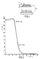
- the detailed construction of the filter 22 will be described later with reference to Figure 4.
- Figure 3 shows another embodiment of a faceplate of a projection television cathode ray tube in which at least the inside surface, but more conveniently both surfaces of the faceplate 12, are convex as viewed from the interior of the envelope.
- the convex surfaces may be part-spherical having a radius of curvature between 150 mm and 730 mm.
- the angle of curvature ⁇ defined as the angle between the optical axis and a normal to the interior convex surface at a point furthest from the centre of the screen, has a maximum angle of 18°.
- the structure 17 of the screen, shown inset, is as described with reference to Figure 2.
- the multilayer interference filter 22 comprises at least 9, but typically between 14 and 30, layers with alternate layers having (H) and low (L) refractive indices (n).
- the optical thickness of each of the layers is n . d , where n is the refractive index of the material and d the actual layer thickness, the optical thickness for the individual layers lies between 0.2 ⁇ f and 0.3 ⁇ f , more particularly between 0.23 ⁇ f and 0.27 ⁇ f with an average optical thickness throughout the stack of 0.25 ⁇ f , where ⁇ f is equal to p x ⁇ , p being a number between 1.20 and 1.33 and ⁇ being the desired central wavelength selected from the spectrum emitted by the cathodoluminescent screen 23.
- the high refractive index layer 25 furthest from the faceplate has an optical thickness in the range specified but this layer 25 may be covered by a thinner, typically 0.125 ⁇ f , terminating layer 26 having a lower (L ⁇ ) refractive index.
- the value of the optical thickness is dependent on the value assigned p and ⁇ .
- p has a value between 1.20 and 1.26.
- the multilayer filter 22 is manufactured by depositing, for example by evaporation or sputtering, the high and low refractive index materials on a suitably prepared faceplate 12 which acts as a substrate.
- the high refractive index material is niobium pentoxide (Nb2O5) and the low refractive index material is silicon dioxide (SiO2).
- niobium pentoxide is used with magnesium fluoride (MgF2) as the low refractive index material.
- MgF2 magnesium fluoride
- Previously interference filters have been made using titanium pentoxide as the high refractive index material and silicon dioxide as the low refractive index material which have been evaporated onto a substrate at temperatures of the order of 300 to 400°C.
- Such filters although having good optical characteristics and bonding between adjacent layers were found to suffer from crazing after the subsequent tube processing steps including sedimentation of the phosphor material, lacquering, evaporation of the aluminium film over the phosphor/lacquer combination and heating to over 400°C to evaporate the lacquer and to get a good vacuum in the tube.
- the cycle time required for the deposition is quite large due to the high substrate temperature needed for the evaporation of TiO2.
- Niobium pentoxide evaporated preferably onto a cool substrate at typically 80°C, although higher temperature substrates can also be used.
- Niobium pentoxide deposited in the whole temperature range from 80°C to 300°C has been found to have a high refractive index and when used with silicon dioxide the difference in refractive indices between them is large enough to get a sufficiently wide reflection band, that is a difference almost as large as that using titanium dioxide as shown in Figure 5.
- Figure 5 light incident on the filter at X L angles up to 32° is transmitted whereas light incident at greater angles is reflected, that is, its transmittance decreases to substantially zero.
- Factors which are considered to have contributed to the crazing include: (1) the fact that the substrates, that is the faceplates, have a large coefficient of expansion, that is one lying in the range 85 x 10 ⁇ 7 to 105 x 10 ⁇ 7 per degree C for temperatures between 0°C and 400°C in contrast to, in particular silicon dioxide which has a small coefficient of expansion. It is believed that niobium pentoxide enhances the overall elasticity of the multilayer filters to some extent thus reducing the crazing. (2) the fact that a large number of layers, typically of the order of 20 layers, have been used. Crazing is enhanced when the number of layers is increased and it is reduced when the number of layers is decreased.
- Nb2O5-SiO2 filters evaporated at substrate temperatures from 80°C to 300°C and Nb2O5-MgF2 filters evaporated at temperatures from 200°C and 300°C were annealed at 460°C substantially immediately after evaporation without any cooling-off of the substrate. This completely eliminated the occurrence of crazing for these filters.
- a suitable glass for a substrate for a cathode ray tube, in particular for projection television is a mixed-alkali glass free or almost free of lead oxide (PbO) and containing barium oxide (BaO) and strontium oxide (SrO) as the main X-ray absorbers.
- PbO lead oxide
- BaO barium oxide
- SrO strontium oxide
Landscapes
- Cathode-Ray Tubes And Fluorescent Screens For Display (AREA)
- Manufacture Of Electron Tubes, Discharge Lamp Vessels, Lead-In Wires, And The Like (AREA)
- Formation Of Various Coating Films On Cathode Ray Tubes And Lamps (AREA)
- Vessels, Lead-In Wires, Accessory Apparatuses For Cathode-Ray Tubes (AREA)
- Video Image Reproduction Devices For Color Tv Systems (AREA)
- Optical Filters (AREA)
Claims (30)
- Verfahren zur Herstellung einer Kathodenstrahlröhre mit einem Kathodolumineszenzschirm und einem Mehrschicht-Interferenzfilter auf einer der Innenseite zugewandten Oberfläche einer Vorderplatte, wobei das Verfahren den Schritt zum Abscheiden abwechselnder Schichten aus einem Werkstoff mit verhältnismäßig hohem Brechnungsindex und einem Werkstoff mit verhältnismäßig niedrigem Index auf der Vorderplatte umfaßt, und der Werkstoff mit einem verhältnismäßig hohen Brechungsindex Niobpentoxid enthält.
- Verfahren nach Anspruch 1, dadurch gekennzeichnet, daß wenigstens 9 abwechselnde Schichten abgeschieden werden, wobei die Schichten eine optische Dicke nd haben, worin n der Brechungsindex der Werkstoffe und d die Dicke sind, und die optische Dicke nd der einzelnen Schichten zwischen 0,2 λf und 0,3 λf liegt, die mittlere optische Dicke der Schichten 0,25 λf beträgt, worin λf gleich p x λ ist, λ die gewünschte zentrale Wellenlänge ist, die aus dem vom Kathodolumineszenzmaterialschirm ausgesandten Spektrum gewählt wird, und p eine Zahl zwischen 1,20 und 1,33 ist.
- Verfahren nach Anspruch 1 oder 2, dadurch gekennzeichnet, daß der Werkstoff mit niedrigem Brechungsindex Siliziumdioxid enthält, und die abwechselnden Schichten bei einer Temperatur im Bereich von im wesentlichen 80°C bis zu im wesentlichen 300°C abgeschieden werden.
- Verfahren nach Anspruch 1 oder 2, dadurch gekennzeichnet, daß der Werkstoff mit niedrigem Brechungsindex Magnesiumfluorid enthält, und die abwechselnden Schichten bei einer Temperatur im Bereich von im wesentlichen 200°C bis zu im wesentlichen 300°C abgeschieden werden.
- Verfahren nach einem der Ansprüche 1 bis 4, dadurch gekennzeichnet, daß das Mehrschicht-Interferenzfilter geglüht wird, während die Vorderplatte auf Überraumtemperatur ist.
- Verfahren nach einem der Ansprüche 1 bis 5, dadurch gekennzeichnet, daß die Vorderplatte ein im wesentlichen bleioxidfreies (PbO) Mischalkaliglas enthält.
- Verfahren nach Anspruch 6, dadurch gekennzeichnet, daß die Vorderplatte einen Ausdehnungskoeffizienten im Bereich von 85 x 10⁻⁷ bis zu 105 x 10⁻⁷ pro °C für Temperaturen zwischen 0 und 400°C hat.
- Verfahren nach Anspruch 6 oder 7, dadurch gekennzeichnet, daß die Glaszusammensetzung in Gewichtsprozent als Hauptbestandteile folgendes enthält:
SiO₂ 50 bis 65 Al₂O₃ 0 bis 4 BaO 0,5 bis 15 SrO 8 bis 22 K₂O 3 bis 11 Na₂O 3 bis 9 Li₂O 0 bis 4 - Verfahren nach einem oder mehreren der Ansprüche 1 bis 8, dadurch gekennzeichnet, daß ein Kathodolumineszenzschirm auf dem Interferenzfilter angebracht ist.
- Verfahren nach Anspruch 2 oder einem der Ansprüche 3 bis 8, wenn abhängig vom Anspruch 2, dadurch gekennzeichnet, daß die letzte Schicht mit mittlerer optischer Dicke von 0,25λf des Filters einen Werkstoff mit einem hohen Brechnungsindex enthält, eine Abschlußschicht auf der letzten Schicht angebracht ist, die Abschlußschicht einen niedrigeren Brechungsindex als der der letzten Schicht ist und eine im wesentlichen geringere Dicke als eine mittlere optische Dicke von 0,25λf hat und wobei ein Kathodoluminszenzschirm auf der Abschlußschicht angebracht ist.
- Kathodenstrählröhre mit einer Vorderplatte, einem Kathodolumineszenzschirm und einem Mehrschicht-Interferenzfilter zwischen der Vorderplatte und dem Schirm, wobei das Filter abwechselnde Schichten eines Werkstoffs mit einer verhältnismäßig hohen Brechungsindex und eines Werkstoffs mit einer verhältnismäßig niedrigen Brechungsindex auf der Vorderplatte enthält, und der Werklstoff mit einem verhältnismäßig hohen Brechungsindex Niobpentoxid enthält.
- Röhre nach Anspruch 11, dadurch gekennzeichnet, daß das Filter wenigstens 9 Schichten enthält, die eine optische Dicke nd haben, worin n der Brechungsindex der Werkstoffe und d die Dicke ist, wobei die optische Dicke nd der einzelnen Schichten zwischen 0,2λf und 0,3λf liegt, die mittlere optische Dicke der Schichten 0,25λf beträgt, worin λf gleich p x λ ist, λ die gewünschte zentrale Wellenlänge ist, die aus dem vom Kathodolumineszenzmaterialschirm ausgesandten Spektrum gewählt wird, und p eine Zahl zwischen 1,20 und 1,33 ist.
- Röhre nach Anspruch 12, dadurch gekennzeichnet, daß das Filter zwischen 14 bis 30 Schichten enthält.
- Röhre nach Anspruch 12 oder 13, dadurch gekennzeichnet, daß nd zwischen 0,23 λf und 0,27 λf liegt.
- Röhre nach einem der Ansprüche 11 bis 14, dadurch gekennzeichnet, daß der Werkstoff mit niedrigem Brechungsindex Siliziumdioxid enthält.
- Röhre nach einem der Ansprüche 11 bis 14, dadurch gekennzeichnet, daß der Werkstoff mit niedrigem Brechungsindex Magnesiumfluorid enthält.
- Röhre nach einem der Ansprüche 11 bis 16, dadurch gekennzeichnet, daß das Filter im wesentlichen direkt nach dem Abscheiden der Schichten geglüht wird.
- Röhre nach einem der Ansprüche 11 bis 17, dadurch gekennzeichnet, daß die Vorderplatte ein im wesentlichen bleioxidfreies (PbO) Mischalkaliglas enthält.
- Verfahren nach Anspruch 18, dadurch gekennzeichnet, daß die Vorderplatte einen Ausdehnungskoeffizienten im Bereich von 85 x 10⁻⁷ bis zu 105 x 10⁻⁷ pro ⁰C für Temperaturen zwischen 0 und 400⁰C hat.
- Verfahren nach Anspruch 18 oder 19, dadurch gekennzeichnet, daß die Glaszusammensetzung in Gewichtsprozent als Hauptbestandteile folgendes enthält:
SiO₂ 50 bis 65 Al₂O₃ 0 bis 4 BaO 0,5 bis 15 SrO 8 bis 22 K₂O 3 bis 11 Na₂O 3 bis 9 Li₂O 0 bis 4 - Röhre nach einem der Ansprüche 11 bis 20, dadurch gekennzeichnet, daß die Innenseite der Vorderplatte mit einem größten Biegungswinkel φ = 18° konvex ist, worin φ der Winkel zwischen der optischen Achse und der Senkrechte auf die konvexe Oberfläche an einem weitest von der Mitte des Schirms befindlichen Punkt ist.
- Röhre nach Anspruch 21, dadurch gekennzeichnet, daß die konvexe Vorderplatte im wesentlichen sphärisch ist und einen Krümmungsradius zwischen 150 und 730 mm hat.
- Röhre nach Anspruch 15 oder 16, dadurch gekennzeichnet, daß der Kathodolumineszenzschirm einen mit Terbium aktivierten grünleuchtenden Leuchtstoff ist, wobei λ = 545 nm beträgt und p eine Zahl zwischen 1,20 und 1,26 ist.
- Röhre nach Anspruch 15 oder 16, dadurch gekennzeichnet, daß der Kathodolumineszenzschirm einen mit Europium aktivierten Yttriumoxid-Leuchtstoff (Y₂O₃:Eu) ist, wobei λ = 612 nm beträgt und p eine Zähl zwischen 1,20 und 1,26 ist.
- Röhre nach Anspruch 15 oder 16, dadurch gekennzeichnet, daß der Kathodolumineszenzschirm ein Zinksulphid-Silber (ZnS:Ag) ist, wobei λ = 460 nm beträgt und p eine Zahl zwischen 1,24 und 1,33 ist.
- Röhre nach Anspruch 12 oder nach einem der Ansprüche 13 bis 15, wenn vom Anspruch 12 abhängig, dadurch gekennzeichnet, daß die mittlere optische Dicke der Schichten 0,25 λf beträgt, die weitest von der Vorderplatte entfernte Schicht mit einer Dicke von im wesentlichen 0.25 λf einen Werkstoff mit einem hohen Brechungsindex enthält, und daß die weitest von der Vorderplatte entfernte Schicht mit dem Kathodolumineszenzmaterial bedeckt ist.
- Röhre nach Anspruch 26, dadurch gekennzeichnet, daß eine Abschlußschicht zwischen der weitest von der Vorderplatte entfernten Schicht mit einem Werkstoff mit hohem Brechungsindex und der Schicht aus Kathodolumineszenzschirmmaterial angebracht ist, wobei die Abschlußschicht eine optische Dicke im wesentlichen von 0,125 λf hat und aus einem Werkstoff mit einem niedrigerem Brechungsindex als der der benachbarten Filterschicht besteht.
- Projektionsfernsehsystem mit drei Kathodenstrahlröhren mit Kathodolumineszenzschirmen, die in verschiedenen Farben leuchten, dadurch gekennzeichnet, daß wenigstens eine der Kathodenstrahlröhren eine Kathodenstrahlröhre nach Anspruch 23 ist.
- Projektionsfernsehsystem mit drei Kathodenstrahlröhren mit Kathodolumineszenzschirmen, die in verschiedenen Farben leuchten, dadurch gekennzeichnet, daß wenigstens eine der Kathodenstrahlröhren eine Kathodenstrahlröhre nach Anspruch 24 ist.
- Projektionsfernsehsystem mit drei Kathodenstrahlröhren mit Kathodolumineszenzschirmen, die in verschiedenen Farben leuchten, dadurch gekennzeichnet, daß wenigstens eine der Kathodenstrahlröhren eine Kathodenstrahlröhre nach Anspruch 25 ist.
Applications Claiming Priority (2)
| Application Number | Priority Date | Filing Date | Title |
|---|---|---|---|
| GB868612358A GB8612358D0 (en) | 1986-05-21 | 1986-05-21 | Cathode ray tube |
| GB8612358 | 1986-05-21 |
Publications (3)
| Publication Number | Publication Date |
|---|---|
| EP0246696A2 EP0246696A2 (de) | 1987-11-25 |
| EP0246696A3 EP0246696A3 (en) | 1990-04-18 |
| EP0246696B1 true EP0246696B1 (de) | 1994-03-30 |
Family
ID=10598202
Family Applications (1)
| Application Number | Title | Priority Date | Filing Date |
|---|---|---|---|
| EP87200874A Expired - Lifetime EP0246696B1 (de) | 1986-05-21 | 1987-05-12 | Verfahren zur Herstellung einer Kathodenstrahlröhre und Kathodenstrahlröhre nach diesem Herstellungsverfahren |
Country Status (5)
| Country | Link |
|---|---|
| US (1) | US5068568A (de) |
| EP (1) | EP0246696B1 (de) |
| JP (1) | JPH07101600B2 (de) |
| DE (1) | DE3789468T2 (de) |
| GB (1) | GB8612358D0 (de) |
Families Citing this family (21)
| Publication number | Priority date | Publication date | Assignee | Title |
|---|---|---|---|---|
| GB8707975D0 (en) * | 1987-04-03 | 1987-05-07 | Philips Nv | Colour cathode ray tube |
| JPH0218841A (ja) * | 1988-07-06 | 1990-01-23 | Mitsubishi Electric Corp | 陰極線管 |
| US4937661A (en) * | 1988-07-11 | 1990-06-26 | North American Philips Corporation | Projection television display tube and device having band pass interference filter |
| NL8802210A (nl) * | 1988-09-08 | 1990-04-02 | Koninkl Philips Electronics Nv | Werkwijze voor het opdampen van een interferentiefilterlaag op de binnenzijde van een beeldvenster, een beeldvenster, een projectie-kathodestraalbuis en een projectie-televisieapparaat. |
| US5209690A (en) * | 1988-09-08 | 1993-05-11 | U.S. Philips Corporation | Method of vapor depositing an interference filter layer on the inside of a display window, a display window, a projection cathode ray tube and a projection television apparatus |
| FR2640425A1 (fr) * | 1988-12-09 | 1990-06-15 | Malifaud Pierre | Procede pour la selection spectrale d'un rayonnement et dispositif de mise en oeuvre, notamment teleprojecteur d'image video |
| FR2642897A1 (fr) * | 1989-02-03 | 1990-08-10 | Thomson Csf | Ecran fluorescent pour tube cathodique |
| US5179318A (en) * | 1989-07-05 | 1993-01-12 | Nippon Sheet Glass Co., Ltd. | Cathode-ray tube with interference filter |
| JP2512204B2 (ja) * | 1990-05-09 | 1996-07-03 | 三菱電機株式会社 | 投写型陰極線管 |
| KR940011569B1 (ko) * | 1990-10-24 | 1994-12-21 | 미쯔비시덴끼 가부시끼가이샤 | 저 반사막을 갖는 음극선관 |
| KR950014541B1 (ko) * | 1991-05-24 | 1995-12-05 | 미쯔비시덴끼 가부시끼가이샤 | 광선택흡수층 또는 뉴트럴 필터층을 갖는 컬러음극선관 |
| US5828493A (en) * | 1992-07-24 | 1998-10-27 | Dielectric Coating Industries | Reflectors |
| JP2981528B2 (ja) * | 1992-12-25 | 1999-11-22 | 三菱電機株式会社 | 陰極線管およびその製造方法 |
| US6074789A (en) * | 1994-03-08 | 2000-06-13 | Philips Electronics N.A. Corp. | Method for producing phosphor screens, and color cathode ray tubes incorporating same |
| JP3368110B2 (ja) | 1995-08-01 | 2003-01-20 | キヤノン株式会社 | 光源装置及び光学機器 |
| KR100453188B1 (ko) | 1999-05-31 | 2004-10-15 | 삼성에스디아이 주식회사 | 콘트라스트가 향상된 음극선관 및 그 제조방법 |
| KR100615154B1 (ko) | 1999-08-19 | 2006-08-25 | 삼성에스디아이 주식회사 | 콘트라스트가 향상된 음극선관 |
| JP4345158B2 (ja) * | 1999-10-15 | 2009-10-14 | ソニー株式会社 | 光学部品の製造装置及び製造方法 |
| JP2002075227A (ja) * | 2000-06-14 | 2002-03-15 | Sharp Corp | 気体放電表示装置およびプラズマアドレス液晶表示装置ならびにその製造方法 |
| KR100786854B1 (ko) * | 2001-02-06 | 2007-12-20 | 삼성에스디아이 주식회사 | 디스플레용 필터막, 그 제조방법 및 이를 포함하는 표시장치 |
| US7019452B2 (en) * | 2003-05-29 | 2006-03-28 | General Electric Company | Boron-containing red light-emitting phosphors and light sources incorporating the same |
Family Cites Families (7)
| Publication number | Priority date | Publication date | Assignee | Title |
|---|---|---|---|---|
| US4065697A (en) * | 1969-02-17 | 1977-12-27 | Owens-Illinois, Inc. | Cathode-ray tube |
| NL6907310A (de) * | 1969-05-13 | 1970-11-17 | ||
| US3805107A (en) * | 1972-02-17 | 1974-04-16 | Corning Glass Works | Faceplate for television picture tube |
| US4310783A (en) * | 1979-05-07 | 1982-01-12 | Temple Michael D | Cathode ray tube face plate construction for suppressing the halo having a low reflection and method |
| NL8301824A (nl) * | 1983-05-24 | 1984-12-17 | Philips Nv | Optisch element bestaande uit een doorzichtig substraat en een antireflectieve bekleding voor het golflengtegebied in het nabije infrarood. |
| NL8402304A (nl) * | 1984-07-20 | 1986-02-17 | Philips Nv | Beeldbuis. |
| GB2176048B (en) * | 1985-05-29 | 1989-07-05 | Philips Nv | Projection television display tube and projection television device comprising at least one such tube |
-
1986
- 1986-05-21 GB GB868612358A patent/GB8612358D0/en active Pending
-
1987
- 1987-05-12 DE DE3789468T patent/DE3789468T2/de not_active Expired - Fee Related
- 1987-05-12 EP EP87200874A patent/EP0246696B1/de not_active Expired - Lifetime
- 1987-05-21 JP JP62122674A patent/JPH07101600B2/ja not_active Expired - Lifetime
-
1990
- 1990-05-15 US US07/524,718 patent/US5068568A/en not_active Expired - Fee Related
Also Published As
| Publication number | Publication date |
|---|---|
| US5068568A (en) | 1991-11-26 |
| EP0246696A3 (en) | 1990-04-18 |
| DE3789468T2 (de) | 1994-10-20 |
| DE3789468D1 (de) | 1994-05-05 |
| JPS62283535A (ja) | 1987-12-09 |
| GB8612358D0 (en) | 1986-06-25 |
| JPH07101600B2 (ja) | 1995-11-01 |
| EP0246696A2 (de) | 1987-11-25 |
Similar Documents
| Publication | Publication Date | Title |
|---|---|---|
| US5068568A (en) | Cathode ray tube having multilayer interference filter | |
| EP0170320B1 (de) | Anzeigevorrichtungsrohr | |
| EP0206381B1 (de) | Projektionsfernsehbildröhre und Projektionsfernsehgerät mit zumindest einer derartigen Röhre | |
| US5599579A (en) | Cathode-ray tube with anti-reflective coating | |
| US4798994A (en) | Low reflectance display device | |
| EP0335680B1 (de) | Kathodenstrahlröhre | |
| US4707635A (en) | Cathode ray tube having a fluorescent layer with varying amounts of silica | |
| US20050242725A1 (en) | Glass composition and paste composition suitable for a plasma display panel, and plasma display panel | |
| US4977347A (en) | Color filter and cathode-ray tube using the color filter | |
| US4684846A (en) | Luminescent screen having restored cavities and display tube having such a screen | |
| US6479928B1 (en) | Cathode ray tube | |
| JP2000206307A (ja) | 機能性フィルム及びこれを採用する陰極線管 | |
| JP2001226147A (ja) | 導電性反射防止膜及びそれが被覆形成された陰極線管用ガラスパネル | |
| EP0925598A1 (de) | Farbanzeigevorrichtung mit farbfilterschichten | |
| JPH11283529A (ja) | 陰極線管及びその製造方法 | |
| JPH10302683A (ja) | 発光表示デバイス | |
| JPH052988A (ja) | 表示装置の反射防止膜形成方法 | |
| JP2001126646A (ja) | 陰極線管 | |
| JPH02160342A (ja) | イメージ管 | |
| JPH03159034A (ja) | 陰極線管フェースプレート | |
| JPS587749A (ja) | カラ−ブラウン管 | |
| JP2005050640A (ja) | 投射型陰極線管用パネルガラスおよび投射型陰極線管 | |
| JPH03241642A (ja) | 陰極線管フェースプレート | |
| JP2002062402A (ja) | 光吸収性反射防止体及び表示装置 | |
| JP2002100309A (ja) | 陰極線管 |
Legal Events
| Date | Code | Title | Description |
|---|---|---|---|
| PUAI | Public reference made under article 153(3) epc to a published international application that has entered the european phase |
Free format text: ORIGINAL CODE: 0009012 |
|
| AK | Designated contracting states |
Kind code of ref document: A2 Designated state(s): DE FR GB NL |
|
| PUAL | Search report despatched |
Free format text: ORIGINAL CODE: 0009013 |
|
| AK | Designated contracting states |
Kind code of ref document: A3 Designated state(s): DE FR GB NL |
|
| 17P | Request for examination filed |
Effective date: 19901016 |
|
| 17Q | First examination report despatched |
Effective date: 19921124 |
|
| GRAA | (expected) grant |
Free format text: ORIGINAL CODE: 0009210 |
|
| AK | Designated contracting states |
Kind code of ref document: B1 Designated state(s): DE FR GB NL |
|
| PG25 | Lapsed in a contracting state [announced via postgrant information from national office to epo] |
Ref country code: NL Effective date: 19940330 |
|
| REF | Corresponds to: |
Ref document number: 3789468 Country of ref document: DE Date of ref document: 19940505 |
|
| ET | Fr: translation filed | ||
| NLV1 | Nl: lapsed or annulled due to failure to fulfill the requirements of art. 29p and 29m of the patents act | ||
| PLBE | No opposition filed within time limit |
Free format text: ORIGINAL CODE: 0009261 |
|
| STAA | Information on the status of an ep patent application or granted ep patent |
Free format text: STATUS: NO OPPOSITION FILED WITHIN TIME LIMIT |
|
| 26N | No opposition filed | ||
| REG | Reference to a national code |
Ref country code: FR Ref legal event code: CD |
|
| PGFP | Annual fee paid to national office [announced via postgrant information from national office to epo] |
Ref country code: GB Payment date: 19960430 Year of fee payment: 10 |
|
| PGFP | Annual fee paid to national office [announced via postgrant information from national office to epo] |
Ref country code: FR Payment date: 19960530 Year of fee payment: 10 |
|
| PGFP | Annual fee paid to national office [announced via postgrant information from national office to epo] |
Ref country code: DE Payment date: 19960724 Year of fee payment: 10 |
|
| PG25 | Lapsed in a contracting state [announced via postgrant information from national office to epo] |
Ref country code: GB Effective date: 19970512 |
|
| GBPC | Gb: european patent ceased through non-payment of renewal fee |
Effective date: 19970512 |
|
| PG25 | Lapsed in a contracting state [announced via postgrant information from national office to epo] |
Ref country code: FR Free format text: LAPSE BECAUSE OF NON-PAYMENT OF DUE FEES Effective date: 19980130 |
|
| PG25 | Lapsed in a contracting state [announced via postgrant information from national office to epo] |
Ref country code: DE Free format text: LAPSE BECAUSE OF NON-PAYMENT OF DUE FEES Effective date: 19980203 |
|
| REG | Reference to a national code |
Ref country code: FR Ref legal event code: ST |