EP0251178A2 - Méthode d'alimentation de solution de régénération dans une machine de développement automatique - Google Patents
Méthode d'alimentation de solution de régénération dans une machine de développement automatique Download PDFInfo
- Publication number
- EP0251178A2 EP0251178A2 EP87109075A EP87109075A EP0251178A2 EP 0251178 A2 EP0251178 A2 EP 0251178A2 EP 87109075 A EP87109075 A EP 87109075A EP 87109075 A EP87109075 A EP 87109075A EP 0251178 A2 EP0251178 A2 EP 0251178A2
- Authority
- EP
- European Patent Office
- Prior art keywords
- replenishing solution
- value
- supplying
- supplied
- less active
- Prior art date
- Legal status (The legal status is an assumption and is not a legal conclusion. Google has not performed a legal analysis and makes no representation as to the accuracy of the status listed.)
- Granted
Links
Images


Classifications
-
- G—PHYSICS
- G03—PHOTOGRAPHY; CINEMATOGRAPHY; ANALOGOUS TECHNIQUES USING WAVES OTHER THAN OPTICAL WAVES; ELECTROGRAPHY; HOLOGRAPHY
- G03D—APPARATUS FOR PROCESSING EXPOSED PHOTOGRAPHIC MATERIALS; ACCESSORIES THEREFOR
- G03D3/00—Liquid processing apparatus involving immersion; Washing apparatus involving immersion
- G03D3/02—Details of liquid circulation
- G03D3/06—Liquid supply; Liquid circulation outside tanks
- G03D3/065—Liquid supply; Liquid circulation outside tanks replenishment or recovery apparatus
Definitions
- the present invention relates generally to a method of supplying a replenishing solution in an automatic developing machine, and more particularly to a method of supplying a replenishing solution in an automatic developing machine in which the deterioration of a developer due to air is compensated for.
- a lithographic developer may be used in obtaining high-contrast development of a photosensitive material.
- the lithographic developer contains only hydroquinone as a developing agent thereof.
- hydroquinone as a developing agent thereof.
- sulfite as a preservative is used in the form of an addition product of formaldehyde therewith, and thus the concentration of free sulfurous acid ions is extremely reduced. Therefore, such lithographic developer is remarkably susceptible to oxidization due to air, and has a material disadvantage in that it cannot possibly be preserved for greater than three days.
- a hydrazine derivative is commonly employed in a method using a stable developer which is not susceptible to oxidization due to air.
- the stability of the developer with respect to oxidization due to air is drastically improved.
- the pH of the developer is set to a value higher than the pH of a normal lithographic developer, so that the pH value tends to easily vary. This gives rise to a problem in that results provided derived from photographic characteristics are prone to vary due to the variations in the pH value.
- the activity of the developer in aqueous form is increased by its oxidization due to air.
- the sensitivity is increased and black spots on film are produced.
- the activity of a replenishing solution employed is typically adjusted to a lower level than that of a development initiating solution used therewith.
- the quantity of a photosensitive material processed per unit time is increased, the quantity of a less-active replenishing solution to be supplied must be increased accordingly. This leads to the disadvantage that the thus-obtained activity of the solution is progressively decreased.
- the present invention providing a method of supplying a replenishing solution in an automatic developing machine comprising the steps of: supplying a less active replenishing solution to the processing tank at the commencement of the present processing operation of the automatic developing machine prior to or in the course of the processing of the photosensitive material, the less active replenishing solution compensating for the deterioration of a developer due to air oxidation during the preceding operating period and the subsequent stop period of the automatic developing machine; and supplying a normally active replenishing solution to the processing tank after completion of the supply of the less active replenishing solution, the normally active replenishing solution compensating for the deterioration of the developer due to the processing of the photosensitive material.
- the value of the required quantity of the less active replenishing solution to be presently supplied is obtained from the result of arithmetic operations based on the value of a predetermined quantity of the less active replenishing solution to be supplied (virtual MDR value) and the value of the quantity of the less active replenishing solution obtained from the operating and stop periods of the preceding supply (true MDR value).
- the inventive method utilizes a less active type of replenishing solution for the purpose of correcting an increase in pH which might be caused by the deterioration of the developer due to its oxidization.
- the level of any increase in pH caused by the deterioration due to oxidization greatly exceeds the level of any decrease in pH caused by development of film. Therefore, the less active replenishing solution is used to correct the increase in pH.
- the less active replenishing solution used with the present invention is defined as a replenishing solution of the type which, when a silver halide photographic photosensitive material containing a hydrazine derivative is subjected to development under fixed conditions, the resultant photographic sensitivity is lower than that realized when development is effected using an initial developing solution.
- the photographic sensitivity mentioned above is represented by the reciprocal of an exposure value which provides a photographic density of 1.5. In this case, the fact that the photographic sensitivity is low means that the value of the photographic sensitivity is equal to or less than 95%.
- the less active replenishing solution used with the present invention may be freely selected from among various solutions less active than an initial developing solution employed. More specifically, the selection can be made from among a solution of the type that shows a pH lower than that of the initial developing solution, a solution obtained by diluting the initial developing solution with water, a solution of the type in which the content of an organic antifoggant is greater than that of the initial developing solution, and a solution of the type in which the water content of a developing agent is less than that of the initial developing solution.
- the difference in pH between the initial developing solution and the less active replenishing solution is preferably in the range of 0.05 to 0.2. If the initial developing solution is to be diluted with water, the ratio of the diluting water to the initial developing solution is preferably in the range of 0.05 to 0.2. Also, the difference in the content of the organic antifoggant is preferably in the range of 20 to 50%.
- the total quantity of the less active replenishing solution to be supplied per unit time is determined substantially in accordance with the length of the unit time.
- the total quantity is more or less varied in accordance with various potential factors such as the activity of the initial developing solution, the activity of the replenishing solution, the kind of an automatic developing machine, the quantity of the developer used and the kind of the photosensitive material.
- the total amount of the less active replenishing solution to be supplied per unit time may be obtained in the following manner. At the commencement of development, the initial developing solution only is added to the developing bath of an automatic developing machine.
- the total quantity of less active replenishing solution to be supplied per unit time can be determined by calculating the quantity of the less active replenishing solution which is required so that the activity of the solution when the machine is again started may be maintained at the same level as the activity of the solution upon the commencement of the preceding development.
- the thus-determined total quantity of less active replenishing solution is suppled by a variety of methods for a predetermined unit time.
- a predetermined quantity of the replenishing solution may be supplied. If the quantity supplied for a predetermined period of time does not reach the aforesaid total quantity to be supplied, the resultant deficiency may be supplied at a given time during the predetermined period of time (for example, upon completion of a day's development work or prior to the commencement of the next day's development work).
- a predetermined quantity that is, the total quantity to be supplied may be reached.
- an active replenishing solution of the type which has substantially the same activity as that of the initial developing solution may be added in accordance with the quantity of the photosensitive material to be processed.
- the quantity required to be supplied so as to compensate for the maximum allowable variation relative to the sensitivity of the solution i.e. the substantial photographic sensitivity of film varied with the activity of processing solution
- a virtual MDR value minimum daily replenishment value
- the quantity which will presently be needed is set as a target MDR value.
- the target MDR value varies in accordance with the past development conditions. More specifically, a true MDR value calculated from the preceding operating period and stop period differs from the preceding quantity of the less active replenishing solution which was actually supplied, so that an oversufficiency or a deficiency occurs in the quantity supplied.
- the true MDR value is greater than that of the quantity of the less active replenishing solution which was actually supplied, the less active replenishing solution is insufficient by an amount equivalent to the resultant difference.
- the true MDR value is an amount to haven been replenished at the preceding processing which can be calculated based upon the actual operating period and stop period. If the deficiency exceeds the virtual MDR value, the resultant excess quantity is supplied immediately after commencement of the present development operation, thereby rendering the target MDR value equal to the virtual MDR value.
- the target MDR is an amount to be replenished at the present processing which is obtained by the preceding true MDR value and the preceding actual replenishing amount. (Refer to Figs. 5(A) and 5(C).)
- the true MDR value is less than the quantity of the less active replenishing solution which was actually supplied, the less active replenishing solution is excessive by an amount equivalent to the resultant difference. Therefore, the present target MDR value is decreased, thereby decreasing the quantity of the less active replenishing solution which is expected to be presently supplied. (Refer to Figs. 5(E) and 5(F).)
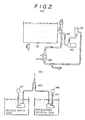
- Fig. 1 diagrammatically shows an automatic developing machine to which a method of supplying a replenishing solution is applicable in accordance with the present invention.
- An automatic developing machine constituting a first preferred embodiment is indicated generally at 10, and has the function of developing an unprocessed film, the function of fixing the thus-developed film, the function of washing the fixed film and the function of drying the washed film.
- the automatic developing machine 10 includes a box 12 for shielding the aforesaid functions from external light.
- the box 12 has a film inserting table 14 at an upper portion of the front thereof, and unprocessed film are inserted through the film inserting table 14.
- the box 12 further has a film stocker 16 at an upper portion of the rear thereof, and processed films are stocked in the film stocker 16.
- An opening through which an unprocessed film is inserted is formed in the portion of the box 12 on which the film inserting table 14 is mounted, and a sensor 80 for detecting the passage of the unprocessed film is disposed in the vicinity of the film inserting opening.
- the sensor 80 is arranged in such a manner that light emitting elements and light receiving elements are disposed in face-to-face relationship with each other in the vicinity of the film inserting opening, the respective pairs of light emitting and receiving elements being provided throughout the width of an inserted film.
- the sensor 80 may be a sensor of the kind in which the light emitting elements cast light on the inserted film and thus the light receiving elements is turned on and off by receiving light reflected from the inserted film.
- a developing tank 18, a fixing tank 20, a washing tank 22 and a drying section 24 are disposed in this order from the film inserting table 14 toward the film stocker 16.
- the box 12 further includes a solution supplying device 28, and a solution circulating device 30 and a control section 34.
- the developing tank 18, the fixing tank 20, the washing tank 22 and the drying section 24 are disposed in the order of film processing, and include a plurality of guide rollers 18A, 20A, 22A and 24A, respectively, so as to convey the film to be processed therealong.
- the plurality of guide rollers 18A, 20A, 22A and 24A constitute in combination a passageway along which the film is conveyed by the rotation of these rollers.
- the solution circulating device 30 disposed in the interior of the box 12 includes a processing-solution filter 36, a heat exchanger 38 and a circulating pump 40.
- a pipe 42 provides communication between the developing tank 18 and the circulating pump 40, and the heat exchanger 38 provides communication between the processing-solution filter 36 and the developing tank 18.
- the solution supplying device 28 includes: a replenishing-solution tank 44 for storing therein a replenishing solution; a diluting-water tank 45 for storing therein diluting water used in diluting the replenishing solution; bellows pumps 46, 47; and motors 48, 49.
- the bellows pump 46 is disposed so as to supply the replenishing solution from the replenishing-solution tank 44, and includes an expandable bellows 46A, a piping 64 and a replenishing-solution sucking portion 50.
- the bellows pumps 47 is also constructed in a similar manner.
- the bellows pumps 46 and 47 are disposed so as to supply the replenishing solution and the diluting water, respectively, to the developing tank 18.
- a diluting-water sucking portion 51 serves to suck the water in place of the replenishing-solution sucking portion 50.
- the bellows 46A is interlockingly connected at one end thereof to a corresponding end of a connecting rod 52 which constitutes a clank mechanism.
- the bellows 46A is further connected at the other end via the piping 46 to the replenishing-solution sucking portion 50 which is placed under the replenishing solution charged in the replenishing-solution tank 44.
- a motor 48 has an output shaft 48A, a rotary disc 54 being mounted on the output shaft 48A, and an eccentric shaft 54A being fixed at a position away from the center of the rotary disc 54.
- the connecting rod 52 is rotatably supported by the eccentric shaft 54A.
- the bellows pump 47 used in supplying the diluting water is also arranged in a manner similar to the bellows pump 46.
- check valves 58 and 60 are accommodated in the replenishing-solution sucking portion 50 placed under the replenishing solution charged in the replenishing-solution tank 44.
- the check valve 58 is disposed so as to open and close an inlet 62 while the check valve 60 is disposed so as to open and close a flow channel 68 which provides communication between the piping 64 and a piping 66. Since the diluting-water tank 45 also has a similar construction, the detailed description is omitted for the sake of simplicity.
- control section 34 is constructed including a CPU 78, an input port 70, an output port 72, a ROM 74 and a RAM 76. Also, counters 75 and 74 are connected to the control section 34 so that measurement may be made with respect to the operating and stop periods of the automatic developing machine 10.
- the sensor 80 is connected to the input port 70 while the output port 72 is connected both to the pump 46 for supplying the replenishing solution and to the pump 47 for suppling the diluting water.
- a film to be processed is inserted through the film inserting table 14.
- the sensor 80 detects the passage of the film and delivers the thus-detected signal to the input port 70 of the control section 34.
- the unprocessed film is conveyed toward the bottom of the developing tank 18 along the film passageway which is formed by the plurality of guide rollers 18A disposed in the developing tank 18.
- the thus-conveyed film is reversed by the motion of the guide rollers 18A disposed at the bottom, and then is conveyed toward the top of the developing tank 18.
- the unprocessed film is passed through the developer stored in the tank 18. While the unprocessed film is being passed through the developing tank 18, it is developed.
- the thus-developed film is further conveyed into the fixing tank 20 along the film passageway which is formed by the plurality of guide rollers 20A arranged in the fixing tank 20, and is fixed therein.
- the film fixed in the fixing tank 20 is then conveyed toward the washing tank 22 along the film passageway which is formed by the plurality of guide rollers 22A arranged in the washing tank 22, and is washed therein.
- the washed film is guided by the plurality of guide rollers 24A toward the drying section 24, and, after being dried, it is accumulated in the film stocker 16.
- the developer stored in the developing tank 18 is circulated by the circulating pump 40. During the circulation, the developer is cleaned through the processing-solution filter 36, and the temperature of the solution is adjusted by the heat exchanger 38 and is recirculated into the developing tank 18.
- the replenishing solution is diluted with the diluting water, and is supplied to the developing tank 18. If the developer deteriorates due to development, the replenishing solution and the diluting water are supplied to the developing tank 18 so that the ratio of the former to the latter may be 1 : 1. Also, if the developer deteriorates due to its oxidization in air, the replenishing solution and the diluting water are supplied to the developing tank 18 so that the ratio of the former to the latter may be 4 : 5. As shown in Fig. 1, in the method of supplying both solutions, the replenishing solution discharged from the replenishing-solution tank 44 and the diluting water discharged from the diluting-water tank 45 are combined midway and supplied to the developing tank 18.
- the bellows 46A is connected to one end of the connecting rod 52 constituting a clank mechanism. Rotation of the output shaft of the motor 48 causes linear movement of such end in the vertical direction, thereby expanding and contracting the bellows 46A.
- the replenishing solution present in the pump 46 and the piping 64 acts on the check valve 58, thereby blocking the inlet 62.
- the operation acts on the replenishing solution present in the flow channel 68 and the check valve 66 is thereby pushed up in the vertical direction. As the consequence, the replenishing solution is discharged through the piping 66.
- the check valve 58 is sucked and moved upward in the vertical direction, thereby causing the replenishing solution to flow into the flow channel 68 through the inlet 62.
- the thus-discharged replenishing solution is passed through the piping 66 and is supplied to the developing tank 18.
- the diluting water is likewise discharged from the diluting-water tank 45 into the piping 66 by means of the bellows pump 47, mixed with the replenishing solution and then supplied to the developing tank 18.
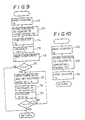
- a method of supplying the replenishing solution by controlling the solution supplying device 38 will be described below with reference to the flow charts shown in Figs. 6, 7 and 8.
- Step 82 judgement is made as to whether or not the automatic developing machine 10 is activated, that is, it is switched on. If the answer is "NO”, the main routine is not executed. If the answer is "YES”, the process proceeds to Step 84 in which judgement is made as to whether or not film processing is started. If the film processing has not yet started, the process returns to Step 82 and the aforementioned Step is repeated until the film processing is started. When the film processing is started, the process proceeds to Step 86, in which judgement is made as to the frequency of transition of the automatic developing machine 10 from the OFF state to the ON state. If a transition concerned is the second or following one, the process proceeds to Step 88, in which arithmetic operations are performed on a quantity X i+1 to be supplied.
- the operating period TP0 is calculated from an interrupt routine such as that shown in Fig. 9, the interrupt routine interrupting the main routine and being executed when the automatic developing machine 10 is set from "ON" to "OFF".
- the stop period TR0 is calculated from an interrupt routine such as that shown in Fig.
- Step 10 the interrupt routine interrupting the main routine and being executed when the automatic developing machine 10 is set from "ON" to "OFF".
- the process proceeds to Step 90, in which judgement is made as to whether or not the film is being processed. If the answer is "YES”, the process proceeds to Step 92, in which both the pump 46 for supplying the replenishing solution and the pump 47 for supplying the diluting water are driven to commence a new supply in accordance with the graph A shown in Fig. 6. At this point of time, the replenishing solution is diluted with the diluting water in the ratio of four to five, and thus the supply of less active replenishing solution is carried out. Following such supply, calculations are performed in Step 94 on a quantity Q of 4 : 5 diluted, less active replenishing solution which was supplied in Step 92.
- Step 96 a comparison is made between the supplied quantity Q and the previously calculated quantity X i+1 to be supplied, and the operations of from steps 90 to 96 are repeated until the calculated quantity X i+1 is completely supplied. If it is judged in Step 86 that the transition is the first one, that is, it is neither the second nor subsequent one, the process jumps to Step 98, and Step 98 and the subsequent Steps are executed. When the supply of the calculated quantity X i+1 is completed, calculations are performed on a quantity Q0 to be supplied to compensate for the deterioration of the developer which is derived from the film processing.
- Step 100 in which both the pump 46 for the replenishing solution and the pump 47 for the diluting water are driven to commence a new supply in accordance with the graph B shown in Fig. 6.
- the replenishing solution is diluted with the diluting water in the ratio of one to one.
- Step 102 calculations are performed on the quantity Q of the 1 : 1 diluted, replenishing solution which was supplied.
- a comparison is made in Step 104 between the quantity Q supplied and the previously calculated quantity Q0 to be supplied. The process from Step 100 to Step 104 is repeated until the calculated quantity Q0 is completely supplied.
- Step 90 while the film is being processed, such processing may be stopped or the power supply of the automatic developing machine 10 may be turned off. In either of these cases, the process proceeds to Step 106, in which calculations are performed on a deficiency q which was not completely supplied. (Refer to the graph C shown in Fig. 6.)
- the deficiency q is stored in the RAM 76 in Step 108. This deficiency q is subsequently supplied by an interrupt routine which interrupts the main routine when the automatic developing machine 10 goes from the OFF state to the ON state.
- the above-described main routine is repetitively executed when the automatic developing machine 10 is ON.
- Step 110 a counter 73 is driven to commence measurement of the operating period TP.
- the process proceeds to Step 112, in which storage of the contents of the counter 75, i.e., stop period TR is carried out.
- the counter 75 is adapted to be driven by the interrupt routine which interrupts the main routine and is executed when the automatic developing machine 10 goes from the OFF state to the ON state.
- the counter 75 is stopped in Step 114, and counts in Step 116 how many transitions from "OFF" to "ON” are carried out.
- the previously stored deficiency q during running of the main routine is read out in Step 118, and judgement is made in Step 120 as to whether the deficiency q is present or absent.
- Step 122 in which the pumps 46 and 47 are driven to commence supply of the deficiency q.
- the replenishing solution is diluted with the diluting water in the ratio of four to five.
- Step 124 in which calculations are performed on the quantity Q supplied.
- the quantity Q supplied is subtracted from the deficiency q in Step 126.
- Step 128 judgesment is made in Step 128 as to whether or not the deficiency q reaches a zero level, that is, the supply of the deficiency q is completed. If the answer is "NO”, the process returns to Step 122, and Steps 122 to 128 are repeatedly executed. When the deficiency q is completely supplied, the process returns to the main routine and this routine is executed.
- Step 130 the counter 75 is driven to commence measurement of the stop period TR.
- the contents of the counter 73, i.e., the operating period TP is stored in Step 132, the counter 73 being adapted to be driven by the interrupt routine which interrupts the main routine and is executed when the automatic developing machine 10 goes from the OFF state to the ON state.
- the counter 73 is stopped in Step 134.
- the second embodiment will now be described below.
- the construction thereof is similar to that of the first embodiment.
- the second embodiment refers to a method of supplying the replenishing solution in a case where the operation period of the automatic developing machine 10 exceeds continuous twenty-four hours.
- Step 136 judgement is made as to whether or not film processing is commenced. If it is judged that the film processing is commenced, the process proceeds to Step 138 in which calculations are performed on the quantity X i+1 to be supplied. Steps 138 and subsequent Steps are the same as Steps 90 to 108 described previously in the first embodiment. Therefore, like reference numerals are used to denote the like or corresponding Steps in the first embodiment, and the description is omitted for the sake of simplicity.
- Step 140 judgement is made as to the presence or absence of the deficiency q to be supplied. If it is judged that the deficiency q is present (refer to the graph E of Fig. 7), the process proceeds to Step 142 in which the pumps 46 and 47 are driven to commence to supply the deficiency q in accordance with the graph F shown in Fig. 7. The quantity Q thus supplied is calculated in Step 144, and in Step 146 the quantity Q supplied is subtracted from the deficiency q. In Step 148, judgement is made as to whether the deficiency q reaches a zero level, that is, the deficiency q is completely supplied.
- Step 142 the process returns to Step 142, and Steps 142 to 148 are repeatedly executed.
- Step 136 the process returns ahead of Step 136, in which judgement is made as to whether or not film processing is resumed.
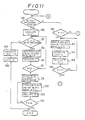
- FIG. 12 there is shown a control routine depicting control exerted in a method of supplying the replenishing solution which is applied to the third embodiment.
- Step 200 judgement is made as to whether or not the automatic developing machine 10 is in operation. If the answer is "NO”, such judgement is repeated. If the answer is "YES”, the process proceeds to Step 204.
- Step 204 Calculations are performed in Step 204 on the preceding true MDR value.
- Step 206 a comparison is made between the preceding quantity which was actually supplied and the preceding target quantity to be supplied. In other words, judgement is made as to whether the preceding processing handled a large or small quantity of film. If the actually supplied quantity is greater than the target quantity to be supplied, it is judged that the preceding processing handled a large quantity of film. Thus, the process proceeds to Step 208. On the other hand, if it is judged that the former quantity is less than the latter quantity, the process proceeds to Step 210.
- Step 208 a comparison is made between the target MDR value and the true MDR value. If the true MDR value is greater than the target MDR value, it is judged that a long period of time has elapsed after completion of the preceding processing. Thus, calculations are performed in Step 214 on a difference l1 between the true MDR value and the target MDR value, and in Step 216 calculations are performed on a difference l2 between the virtual MDR value and the target MDR value.
- Step 218 the differences ll and l2 are compared in Step 218. If l1 > l2, the quantity supplied is greater than the difference l2 between the virtual MDR value and the target MDR value. Thus, the process proceeds to Step 220 in which the replenishing solution is supplied in an amount equivalent to the resultant difference (l1 - l2). The process proceeds to Step 222, in which the target MDR value is set to the virtual MDR value to obtain the succeeding target MDR value. (Refer to the graph A of Fig. 5.)
- Step 226 the aforesaid difference l1 is added to the target MDR value to obtain the succeeding target MDR value. Accordingly, in this case, no supply of the replenishing solution is carried out. (Refer to the graph B of Fig. 5.)
- Step 210 If it is judged in Step 206 that the target MDR value is equal to or greater than the actually supplied quantity, that is, the preceding processing handled a small quantity of film, the process proceeds to Step 210., The actually supplied quantity is compared with the true quantity to be supplied. If the true quantity is equal to or greater than the MDR value, the process proceeds to Step 228. After calculations have been performed on the difference l1 between the true MDR value and the quantity supplied, the process proceeds to Step 216. Subsequently, the process proceeds to Steps 218, 220 and 222 in this order. (Refer to the graph C of Fig. 5.) Alternatively, the process proceeds from Step 218 to Step 226. (Refer to the graph D of Fig. 5.)
- Step 210 determines whether the actually supplied quantity is greater than the true MDR value. If it is judged in Step 210 that the actually supplied quantity is greater than the true MDR value, a short period of time has elapsed after the preceding processing has been completed. Thus, the process proceeds to Step 230, in which calculations are performed on the differencel between the actually supplied quantity and the true MDR value. Subsequently, in Step 232, this l is subtracted from the target MDR value to obtain the succeeding target MDR value. In this case as well, no supply of the replenishing solution is carried out. (Refer to the graph E of Fig. 5.
- Step 208 if the target MDR value is greater than the true MDR value, it is judged that a short period of time has elapsed after completion of the processing of a large quantity of film. Thus, the process proceeds to Step 234. After the difference l1 between the target MDR value and the true MDR value has been calculated in Step 234, the process proceeds to Step 232. (Refer to the graph F of Fig. 5.)
Landscapes
- Physics & Mathematics (AREA)
- General Physics & Mathematics (AREA)
- Photographic Processing Devices Using Wet Methods (AREA)
Applications Claiming Priority (4)
| Application Number | Priority Date | Filing Date | Title |
|---|---|---|---|
| JP151214/86 | 1986-06-27 | ||
| JP61151214A JPS638646A (ja) | 1986-06-27 | 1986-06-27 | 自動現像機の補充液補充方法 |
| JP61237569A JPH0697337B2 (ja) | 1986-10-06 | 1986-10-06 | 自動現像機の補充液補充方法 |
| JP237569/86 | 1986-10-06 |
Publications (3)
| Publication Number | Publication Date |
|---|---|
| EP0251178A2 true EP0251178A2 (fr) | 1988-01-07 |
| EP0251178A3 EP0251178A3 (en) | 1990-03-14 |
| EP0251178B1 EP0251178B1 (fr) | 1994-04-20 |
Family
ID=26480529
Family Applications (1)
| Application Number | Title | Priority Date | Filing Date |
|---|---|---|---|
| EP87109075A Expired - Lifetime EP0251178B1 (fr) | 1986-06-27 | 1987-06-24 | Méthode d'alimentation de solution de régénération dans une machine de développement automatique |
Country Status (4)
| Country | Link |
|---|---|
| US (1) | US4786584A (fr) |
| EP (1) | EP0251178B1 (fr) |
| DE (1) | DE3789634T2 (fr) |
| DK (1) | DK173941B1 (fr) |
Cited By (5)
| Publication number | Priority date | Publication date | Assignee | Title |
|---|---|---|---|---|
| GB2196748B (en) * | 1986-10-22 | 1990-10-31 | Solartron Electronics Inc | Strain gage beam having integral overload protection |
| EP0517209A3 (en) * | 1991-06-07 | 1993-05-05 | Eastman Kodak Company | Processor with automatic chemical dilution and mixing system |
| EP0867765A1 (fr) * | 1997-03-27 | 1998-09-30 | Eastman Kodak Company | Methode et appareil pour le traitement de matériaux photographiques photosensibles |
| EP0909983A1 (fr) * | 1997-10-17 | 1999-04-21 | Eastman Kodak Company | Méthode de traitement de matériau photographique |
| EP3168704A1 (fr) | 2015-11-12 | 2017-05-17 | Hexagon Technology Center GmbH | Inspection en 3d d'une surface au moyen de véhicules mobiles |
Families Citing this family (7)
| Publication number | Priority date | Publication date | Assignee | Title |
|---|---|---|---|---|
| JPS6128949A (ja) * | 1984-05-16 | 1986-02-08 | Konishiroku Photo Ind Co Ltd | ハロゲン化銀カラ−写真感光材料の処理方法 |
| EP0649055B1 (fr) * | 1993-10-14 | 2000-03-15 | Konica Corporation | Méthode de remplissage d'un développateur |
| US5436118A (en) * | 1994-03-31 | 1995-07-25 | Eastman Kodak Company | Method of processing silver halide photographic elements using a low volume thin tank processing system |
| EP0752618A3 (fr) * | 1995-06-12 | 1997-01-22 | E.I. Du Pont De Nemours And Company | Révélateur à base d'hydroquinone, procédé de recyclage de ce révélateur usagé et le révélateur recyclé |
| GB2306686A (en) * | 1995-10-18 | 1997-05-07 | Kodak Ltd | Processing system for developing photographic materials |
| US7078162B2 (en) * | 2003-10-08 | 2006-07-18 | Eastman Kodak Company | Developer regenerators |
| US20050076801A1 (en) * | 2003-10-08 | 2005-04-14 | Miller Gary Roger | Developer system |
Family Cites Families (12)
| Publication number | Priority date | Publication date | Assignee | Title |
|---|---|---|---|---|
| US3647462A (en) * | 1969-02-19 | 1972-03-07 | Eastman Kodak Co | Methods and materials for replenishment of developers for color photographic films (b) |
| US3647461A (en) * | 1969-02-19 | 1972-03-07 | Eastman Kodak Co | Methods and materials for replenishment of developers for color photographic films |
| DE2004893A1 (en) * | 1970-02-04 | 1971-08-12 | Klinisch & Co, 6000 Frankfurt | Two-component regenerator soln for developing machine |
| US3970457A (en) * | 1974-04-22 | 1976-07-20 | The Mead Corporation | Automatic replenishment method and apparatus for photographic processes |
| CH618800A5 (fr) * | 1976-02-04 | 1980-08-15 | Agfa Gevaert Nv | |
| FR2379096A1 (fr) * | 1977-01-28 | 1978-08-25 | Fuji Photo Film Co Ltd | Procede de regeneration d'un revelateur photolithographique |
| DE3268792D1 (en) * | 1981-07-23 | 1986-03-13 | Du Pont | Stable photographic developer and replenisher therefor |
| US4372666A (en) * | 1981-11-16 | 1983-02-08 | Pako Corporation | Automatic variable-quantity/variable-time anti-oxidation replenisher control system |
| JPS60220344A (ja) * | 1984-04-16 | 1985-11-05 | Konishiroku Photo Ind Co Ltd | 発色現像液補充剤組成物の補充方法 |
| JPS6250828A (ja) * | 1985-08-30 | 1987-03-05 | Konishiroku Photo Ind Co Ltd | 処理液の補充方法 |
| JPH0679142B2 (ja) * | 1985-10-18 | 1994-10-05 | 富士写真フイルム株式会社 | 現像処理方法 |
| US4732666A (en) * | 1985-10-25 | 1988-03-22 | Sentrachem Limited | Froth flotation |
-
1987
- 1987-06-24 DE DE3789634T patent/DE3789634T2/de not_active Expired - Fee Related
- 1987-06-24 EP EP87109075A patent/EP0251178B1/fr not_active Expired - Lifetime
- 1987-06-26 DK DK198703266A patent/DK173941B1/da not_active IP Right Cessation
- 1987-06-29 US US07/067,182 patent/US4786584A/en not_active Expired - Lifetime
Cited By (7)
| Publication number | Priority date | Publication date | Assignee | Title |
|---|---|---|---|---|
| GB2196748B (en) * | 1986-10-22 | 1990-10-31 | Solartron Electronics Inc | Strain gage beam having integral overload protection |
| EP0517209A3 (en) * | 1991-06-07 | 1993-05-05 | Eastman Kodak Company | Processor with automatic chemical dilution and mixing system |
| EP0867765A1 (fr) * | 1997-03-27 | 1998-09-30 | Eastman Kodak Company | Methode et appareil pour le traitement de matériaux photographiques photosensibles |
| US5933674A (en) * | 1997-03-27 | 1999-08-03 | Eastman Kodak Company | Processing of photographic light sensitive materials and apparatus therefor |
| EP0909983A1 (fr) * | 1997-10-17 | 1999-04-21 | Eastman Kodak Company | Méthode de traitement de matériau photographique |
| US6164845A (en) * | 1997-10-17 | 2000-12-26 | Eastman Kodak Company | Processing photographic material |
| EP3168704A1 (fr) | 2015-11-12 | 2017-05-17 | Hexagon Technology Center GmbH | Inspection en 3d d'une surface au moyen de véhicules mobiles |
Also Published As
| Publication number | Publication date |
|---|---|
| DK326687D0 (da) | 1987-06-26 |
| EP0251178B1 (fr) | 1994-04-20 |
| EP0251178A3 (en) | 1990-03-14 |
| DE3789634D1 (de) | 1994-05-26 |
| DE3789634T2 (de) | 1994-08-04 |
| US4786584A (en) | 1988-11-22 |
| DK173941B1 (da) | 2002-03-04 |
| DK326687A (da) | 1987-12-28 |
Similar Documents
| Publication | Publication Date | Title |
|---|---|---|
| US4786584A (en) | Method of supplying replenishing solution in automatic developing machine | |
| EP0515454B1 (fr) | Procede et appareil de traitement photographique | |
| CA1041823A (fr) | Mode et dispositif de recharge automatique lors de procedes photographiques | |
| EP0546136B1 (fr) | Appareil de traitement photographique | |
| DE69120717T2 (de) | Verfahren zum Zufügen von Wasser zum Gebrauch in einem Behandlungsgerät für photoempfindliches Material | |
| EP0557330B1 (fr) | Procede de developpement d'un materiau de support photographique couleur d'halogenure d'argent | |
| US4372665A (en) | Automatic variable-quantity/fixed-time anti-oxidation replenisher control system | |
| EP0623842A1 (fr) | Appareil de développement photographique | |
| US5124239A (en) | Method of replenishing photographic processing apparatus with processing solution | |
| EP0241858B1 (fr) | Méthode d'approvisionnement de liquide de régénération dans une machine de développement automatique | |
| WO1992007301A1 (fr) | Appareil de traitement photographique | |
| US5439784A (en) | Method and apparatus for photographic processing solution replenishment | |
| JPH0621953B2 (ja) | 写真感光材料用現像処理装置 | |
| JPS638646A (ja) | 自動現像機の補充液補充方法 | |
| US5842074A (en) | Photographic developing apparatus and method of supplying water to the apparatus | |
| US5619742A (en) | Photographic processing condition managing method, and method and apparatus for managing image forming devices | |
| US5736304A (en) | Method of processing black-and-white photographic materials | |
| EP0741324A1 (fr) | Traitement photographique | |
| JP2704668B2 (ja) | カラー印画紙の処理方法 | |
| US5683839A (en) | Method of processing black and white photographic silver halide materials | |
| JPH06214368A (ja) | 感光材料処理装置 | |
| JPH075644A (ja) | 自動現像機の処理液補充方法 | |
| JP2942672B2 (ja) | 補充液の補充方法及び補充装置 | |
| EP0742481A1 (fr) | Procédé de traitement de matériaux photographiques en noir et blanc | |
| JP3364337B2 (ja) | 感光材料処理装置の補充液補充方法 |
Legal Events
| Date | Code | Title | Description |
|---|---|---|---|
| PUAI | Public reference made under article 153(3) epc to a published international application that has entered the european phase |
Free format text: ORIGINAL CODE: 0009012 |
|
| AK | Designated contracting states |
Kind code of ref document: A2 Designated state(s): DE GB |
|
| PUAL | Search report despatched |
Free format text: ORIGINAL CODE: 0009013 |
|
| AK | Designated contracting states |
Kind code of ref document: A3 Designated state(s): DE GB |
|
| 16A | New documents despatched to applicant after publication of the search report | ||
| 17P | Request for examination filed |
Effective date: 19900405 |
|
| 17Q | First examination report despatched |
Effective date: 19920416 |
|
| GRAA | (expected) grant |
Free format text: ORIGINAL CODE: 0009210 |
|
| AK | Designated contracting states |
Kind code of ref document: B1 Designated state(s): DE GB |
|
| REF | Corresponds to: |
Ref document number: 3789634 Country of ref document: DE Date of ref document: 19940526 |
|
| RIN2 | Information on inventor provided after grant (corrected) |
Free format text: ENDO, YOICHI |
|
| PLBE | No opposition filed within time limit |
Free format text: ORIGINAL CODE: 0009261 |
|
| STAA | Information on the status of an ep patent application or granted ep patent |
Free format text: STATUS: NO OPPOSITION FILED WITHIN TIME LIMIT |
|
| 26N | No opposition filed | ||
| REG | Reference to a national code |
Ref country code: GB Ref legal event code: IF02 |
|
| PGFP | Annual fee paid to national office [announced via postgrant information from national office to epo] |
Ref country code: GB Payment date: 20020528 Year of fee payment: 16 |
|
| PGFP | Annual fee paid to national office [announced via postgrant information from national office to epo] |
Ref country code: DE Payment date: 20020729 Year of fee payment: 16 |
|
| PG25 | Lapsed in a contracting state [announced via postgrant information from national office to epo] |
Ref country code: GB Free format text: LAPSE BECAUSE OF NON-PAYMENT OF DUE FEES Effective date: 20030624 |
|
| PG25 | Lapsed in a contracting state [announced via postgrant information from national office to epo] |
Ref country code: DE Free format text: LAPSE BECAUSE OF NON-PAYMENT OF DUE FEES Effective date: 20040101 |
|
| GBPC | Gb: european patent ceased through non-payment of renewal fee |
Effective date: 20030624 |