EP0264640B1 - Elektronisch gesteuertes Einspritzsystem - Google Patents
Elektronisch gesteuertes Einspritzsystem Download PDFInfo
- Publication number
- EP0264640B1 EP0264640B1 EP87113751A EP87113751A EP0264640B1 EP 0264640 B1 EP0264640 B1 EP 0264640B1 EP 87113751 A EP87113751 A EP 87113751A EP 87113751 A EP87113751 A EP 87113751A EP 0264640 B1 EP0264640 B1 EP 0264640B1
- Authority
- EP
- European Patent Office
- Prior art keywords
- fuel
- pressure
- injectors
- pump
- injector
- Prior art date
- Legal status (The legal status is an assumption and is not a legal conclusion. Google has not performed a legal analysis and makes no representation as to the accuracy of the status listed.)
- Expired - Lifetime
Links
- 239000000446 fuel Substances 0.000 title claims abstract description 126
- 238000002347 injection Methods 0.000 title claims abstract description 99
- 239000007924 injection Substances 0.000 title claims abstract description 99
- 238000002485 combustion reaction Methods 0.000 claims abstract description 14
- 238000011144 upstream manufacturing Methods 0.000 claims abstract description 8
- 230000001052 transient effect Effects 0.000 claims abstract description 7
- 238000005086 pumping Methods 0.000 claims description 20
- 230000000694 effects Effects 0.000 claims description 2
- 230000008901 benefit Effects 0.000 description 4
- 230000015572 biosynthetic process Effects 0.000 description 2
- 239000002828 fuel tank Substances 0.000 description 2
- 230000010349 pulsation Effects 0.000 description 2
- 230000004044 response Effects 0.000 description 2
- 238000007789 sealing Methods 0.000 description 2
- 238000010276 construction Methods 0.000 description 1
- 239000002826 coolant Substances 0.000 description 1
- 230000001627 detrimental effect Effects 0.000 description 1
- 238000007599 discharging Methods 0.000 description 1
- 239000012530 fluid Substances 0.000 description 1
- 230000006870 function Effects 0.000 description 1
- 230000009467 reduction Effects 0.000 description 1
- 230000001105 regulatory effect Effects 0.000 description 1
- 230000007363 regulatory process Effects 0.000 description 1
- 239000000243 solution Substances 0.000 description 1
- 230000003068 static effect Effects 0.000 description 1
- 238000013024 troubleshooting Methods 0.000 description 1
- 238000003466 welding Methods 0.000 description 1
Images


Classifications
-
- F—MECHANICAL ENGINEERING; LIGHTING; HEATING; WEAPONS; BLASTING
- F02—COMBUSTION ENGINES; HOT-GAS OR COMBUSTION-PRODUCT ENGINE PLANTS
- F02M—SUPPLYING COMBUSTION ENGINES IN GENERAL WITH COMBUSTIBLE MIXTURES OR CONSTITUENTS THEREOF
- F02M59/00—Pumps specially adapted for fuel-injection and not provided for in groups F02M39/00 -F02M57/00, e.g. rotary cylinder-block type of pumps
- F02M59/20—Varying fuel delivery in quantity or timing
- F02M59/36—Varying fuel delivery in quantity or timing by variably-timed valves controlling fuel passages to pumping elements or overflow passages
- F02M59/366—Valves being actuated electrically
-
- F—MECHANICAL ENGINEERING; LIGHTING; HEATING; WEAPONS; BLASTING
- F02—COMBUSTION ENGINES; HOT-GAS OR COMBUSTION-PRODUCT ENGINE PLANTS
- F02M—SUPPLYING COMBUSTION ENGINES IN GENERAL WITH COMBUSTIBLE MIXTURES OR CONSTITUENTS THEREOF
- F02M47/00—Fuel-injection apparatus operated cyclically with fuel-injection valves actuated by fluid pressure
- F02M47/02—Fuel-injection apparatus operated cyclically with fuel-injection valves actuated by fluid pressure of accumulator-injector type, i.e. having fuel pressure of accumulator tending to open, and fuel pressure in other chamber tending to close, injection valves and having means for periodically releasing that closing pressure
- F02M47/027—Electrically actuated valves draining the chamber to release the closing pressure
-
- F—MECHANICAL ENGINEERING; LIGHTING; HEATING; WEAPONS; BLASTING
- F02—COMBUSTION ENGINES; HOT-GAS OR COMBUSTION-PRODUCT ENGINE PLANTS
- F02M—SUPPLYING COMBUSTION ENGINES IN GENERAL WITH COMBUSTIBLE MIXTURES OR CONSTITUENTS THEREOF
- F02M63/00—Other fuel-injection apparatus having pertinent characteristics not provided for in groups F02M39/00 - F02M57/00 or F02M67/00; Details, component parts, or accessories of fuel-injection apparatus, not provided for in, or of interest apart from, the apparatus of groups F02M39/00 - F02M61/00 or F02M67/00; Combination of fuel pump with other devices, e.g. lubricating oil pump
- F02M63/02—Fuel-injection apparatus having several injectors fed by a common pumping element, or having several pumping elements feeding a common injector; Fuel-injection apparatus having provisions for cutting-out pumps, pumping elements, or injectors; Fuel-injection apparatus having provisions for variably interconnecting pumping elements and injectors alternatively
- F02M63/0225—Fuel-injection apparatus having a common rail feeding several injectors ; Means for varying pressure in common rails; Pumps feeding common rails
-
- F—MECHANICAL ENGINEERING; LIGHTING; HEATING; WEAPONS; BLASTING
- F02—COMBUSTION ENGINES; HOT-GAS OR COMBUSTION-PRODUCT ENGINE PLANTS
- F02M—SUPPLYING COMBUSTION ENGINES IN GENERAL WITH COMBUSTIBLE MIXTURES OR CONSTITUENTS THEREOF
- F02M65/00—Testing fuel-injection apparatus, e.g. testing injection timing ; Cleaning of fuel-injection apparatus
- F02M65/005—Measuring or detecting injection-valve lift, e.g. to determine injection timing
-
- F—MECHANICAL ENGINEERING; LIGHTING; HEATING; WEAPONS; BLASTING
- F02—COMBUSTION ENGINES; HOT-GAS OR COMBUSTION-PRODUCT ENGINE PLANTS
- F02B—INTERNAL-COMBUSTION PISTON ENGINES; COMBUSTION ENGINES IN GENERAL
- F02B2275/00—Other engines, components or details, not provided for in other groups of this subclass
- F02B2275/14—Direct injection into combustion chamber
-
- F—MECHANICAL ENGINEERING; LIGHTING; HEATING; WEAPONS; BLASTING
- F02—COMBUSTION ENGINES; HOT-GAS OR COMBUSTION-PRODUCT ENGINE PLANTS
- F02M—SUPPLYING COMBUSTION ENGINES IN GENERAL WITH COMBUSTIBLE MIXTURES OR CONSTITUENTS THEREOF
- F02M2200/00—Details of fuel-injection apparatus, not otherwise provided for
- F02M2200/24—Fuel-injection apparatus with sensors
-
- Y—GENERAL TAGGING OF NEW TECHNOLOGICAL DEVELOPMENTS; GENERAL TAGGING OF CROSS-SECTIONAL TECHNOLOGIES SPANNING OVER SEVERAL SECTIONS OF THE IPC; TECHNICAL SUBJECTS COVERED BY FORMER USPC CROSS-REFERENCE ART COLLECTIONS [XRACs] AND DIGESTS
- Y02—TECHNOLOGIES OR APPLICATIONS FOR MITIGATION OR ADAPTATION AGAINST CLIMATE CHANGE
- Y02T—CLIMATE CHANGE MITIGATION TECHNOLOGIES RELATED TO TRANSPORTATION
- Y02T10/00—Road transport of goods or passengers
- Y02T10/10—Internal combustion engine [ICE] based vehicles
- Y02T10/12—Improving ICE efficiencies
Definitions
- the present invention relates to an accumulator type fuel injection system for an internal combustion engine as defined in the pre-characterizing clause of claim 1.
- a fuel injection system of this type is disclosed in DE-A-32 27 742 and corresponding US-A-4,566,416.
- This known injection system employs injectors provided with an accumulator volume or chamber with a volume substantially larger than the maximum volume of fuel injected during each injection event.
- This accumulator chamber is located in the injector body upstream of the seat of the injector needle valve.
- the injection orifices are located downstream of this seat. These orifices communicate with the combustion chamber of the related internal combustion engine.
- the fuel stored in the accumulator chamber under high pressure is partly discharged through the injection orifices during each injection event with a simultaneous pressure drop in the accumulator chamber.
- Each accumulator chamber communicates with the high pressure fuel supply line of the injection system by means of a restricted passage or orifice.
- the orifice due to its small cross-sectional flow area, prevents the formation of noticeable pressure waves in the fuel supply lines during each injection event. Such pressure waves would highly affect the uniform fuel distribution in a multicylinder engine and the stability of the injection events of a single injector from cycle to cycle.
- a very uniform fuel distribution from cylinder to cylinder must be achieved in a multicylinder engine at each engine operating point. The same holds true for each injector from cycle to cycle.
- a plenum fuel chamber communicating with the fuel supply lines of all injectors of the injection system is provided in order to achieve the desired uniform fuel distribution. Due to its relatively large volume, the plenum chamber evens out the pressure pulsations created by the high pressure fuel supply pump and thus creates a constant pressure level for all injectors. However, this relatively large volume of the plenum chamber does not allow to rapidly increase and drop the fuel pressure in the plenum chamber. Therefore, a quick adjustment of the fuel injection pressure to the varying engine operating conditions, in particular during transient speed and load conditions, is not possible.
- DE-A-26 47 744 discloses a fuel injection system which is provided with a pressure accumulator arranged downstream of a high pressure pump.
- a pressure relief valve keeps the pressure in the system constant for all operating conditions of the engine.
- the present invention it is therefore possible to largely reduce the total high pressure volume of the injection system (by over an order of magnitude) compared to the prior art systems referred to earlier. This allows to rapidly adjust the injection pressure to the varying driver demands and thus to achieve a fast response during transient operation of the engine. This makes the injection system also suitable for use in passenger car engines without the need of an overdimensioned fuel injection pump or of a complex control scheme taking care of the transient engine operating conditions.
- the disclosed electronically controlled fuel injection system is employed in a four cylinder engine 2.
- the fuel comes from a fuel tank 6 and reaches through a low pressure pipe 6a a fuel filter 8 and, through another low pressure pipe 9, a high pressure pump 10.
- the drive shaft 5 of pump 10 which can be a one- or multicylinder pump, depending on the specific application, is driven by a shaft 3 of the engine 2 with a constant drive ratio, for example by means of a gear or a tooth-belt 11.
- the motion of the plunger or plungers of pump 10 shall be harmonic and each pumping event shall take place over a large angle of rotation of the pump drive shaft 5 and thus also of the engine crankshaft 7.
- the maximum fuel delivery of the pump 10 per revolution of the engine crankshaft 7 shall be substantially equal to the maximum fuel quantity delivered to the engine and spilled back to the tank by the totality of the injectors 4 of the injection system in one revolution of the engine crankshaft 7.
- the number of pumping strokes taking place shall be the same or an entire multiple of the number of injecticn events.
- the engine 2 is a four cycle engine
- two combustion events and thus two injection events take place during each revolution of the engine crankshaft 7.
- Each pumping event would then take place during an 180 degrees rotation of crankshaft 7.
- the injection event of each of the injectors 4 of the injection system takes place during the pumping stroke of any one of the pumping plungers of the pump 10.
- a single-plunger pump 10 driven by the engine 2 with a drive ratio between pump shaft 5 and crankshaft 7 of 2:1.
- a single-plunger pump 10 driven with a 1:1 drive ratio but with a construction providing two strokes of the plunger per revolution of the pump shaft 5 could be employed.
- the outlet of pump 10 is connected to a plurality of high pressure lines 12 wich belong to the high pressure section of the injection system.
- the fuel delivered by the pump 10 to this high pressure section of the injection system and to the high pressure lines 12 can be regulated, depending on the engine operating conditions, within the pump 10 in a manner known from already employed in-line or distributor type fuel injection pumps. As shown in the drawings, this regulating process is taken care of by an electronic control unit 20 and appropriate actuators 21 (not shown in detail) placed within the housing of the pump 10 and connected to the control unit 20 by means of an electrical connection 19.
- the control unit 20 also operates the solenoid 74 of each injector 4.
- the main input signals to the control unit 20 are the crankshaft angle position sensed by a pick-up sensor 22 and the position of the throttle pedal 24. Further input signals 26 such as engine coolant temperature, intake air or boost pressure etc. can be fed to the control unit 20 as well.
- the control unit 20 is powered by a battery 28.
- the control unit 20 comprises a one-chip microprocessor and the required input and output power modules.
- the desired relationships between the input signals and the output signals to the injector solenoids 74 and to the actuator 21 of the pump 10 are programmed into the microprocessor.
- the required data needed to determine the momentary value of the output signals as a function of the momentary input signals are stored in the microprocessor memory.
- the microprocessor can also be used to perform troubleshooting diagnostics of the combined engine and fuel-injection systems.
- the high pressure section of the injection system of Fig. 1 consists of the high pressure pipes 12 and the high pressure section 34 of each injector 4. From each injector 4 a low pressure spill pipe 38 and a low pressure pipe 40 connecting all pipes 38 returns low pressure fuel released form each injector 4 back to the fuel tank 6.
- each high pressure pipe 12 provides for a direct flow path without any restriction from the high pressure pump 10 to each injector 4.
- a direct and unrestricted hydraulic connection is made between the outlet side of the high pressure pump 10 to the region around the seat of the injector needle valve in the tip of each injector 4 by means of the high pressure pipes 12 and the high pressure section 34 of the injector 4.
- an injector design insensitive to pressure waves must be used in conjunction with this system in order to maintain the desired uniformity of fuel delivery of the injectors 4.
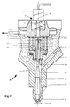
- a preferred design of such an injector 4 is shown in Fig. 2.
- each pumping event takes place over a large angle of rotation of the engine crankshaft 7.
- Fig. 1 with a two plunger pump, driven by the engine with a drive ratio of 1:1, each pumping event takes place over 180 degrees of rotation of the crankshaft 7.
- the slow, harmonic pumping motion makes it possible to avoid high pressure peaks at a high engine speed, which would be detrimental to the mechanical durability of the components of the injection system.
- the injection pressure can be maintained at a high level when the engine speed is slow. Both attributes allow to optimise the engine performance with respect to power, noise and emissions.
- the injection system's high pressure section is built in such a way that it is symmetrical with respect to the arrangement of the fuel lines 12. Accordingly, the time for a pressure wave to travel from anyone of the injectors 4 to the outlet side of the pump 10 or vice-versa will be the same for all injectors 4 employed.
- each injector 4 is connected by fuel lines 12 of equal length directly to the housing of the pump 10. In this case a hydraulic connection between the fuel lines 12 would also be provided within the housing of the pump 10.
- Fig. 2 shows the main portion of an injector 4 of preferred design, which can be employed advantageously in conjunction with the injection system of Fig. 1.
- the pressurized fuel coming from one of the high pressure lines 12 shown in Fig. 1 enters the injector 4 through bore 42, which is machined into the housing 44 of the injector 4.
- the bore 42 is connected to a bore 54 which extends downwards in axial direction to the needle valve seat 56.
- An injector needle valve 52 is arranged within the bore 54 and extends downwards into the injector neck 55 and to the needle valve seat 56. As shown in Fig. 2 the tip of the needle valve 52 is engaged with the valve seat 56 and closes the injection orifices 58, thus preventing pressurized fuel to be injected from the bore 54 through the seat 56 and the injection orifices 58 into the combustion chamber of the related internal combustion engine (not shown). As already mentioned, the cross-sections of the flow passages from bore 42 to the valve seat 56 are big compared to the total cross-sectional flow area of all injection orifices 58. The needle valve 52 can be momentarily shifted axially in order to open the injection orifices 58 and to allow injection of a desired quantity of fuel.
- the injector needle valve 52 On the end opposite to its tip, the injector needle valve 52 is provided with a needle valve piston 60 with two sections of different outer diameters.
- the outer diameter of the lower section 63 is tightly matched to the inner diameter of a guide-piece 62.
- the latter has an enlarged portion which, together with a sealing ring 64, is pressed against a shoulder 44a of the injector housing 44 by an internal hexagon-screw 66, thus sealing the high pressure section of the injector 4.
- the outer diameter of the upper section 69 of the needle valve piston 60 is larger than the outer diameter of the lower section 63.
- the needle valve piston 60 with its two sections 63, 69 of different outer diameters is firmly connected to the injector needle valve 52, either because it is made of one piece with the injector needle valve 52 as shown on Fig. 2, or by firmly connecting the two parts 52, 60 to one another, for example by press-fitting or by welding the parts together.
- a bore 65 machined in the inner part of the needle valve piston 60 is connected at one end to the bore 54 of the injector 4.
- the other end of bore 65 is connected to a restricted orifice 67 with a substantially smaller flow cross-sectional area compared to the cross-sectional area of bore 65.
- the other end of the orifice 67 extends through the upper end surface 69a of the thicker section 69 of the needle valve piston 60.
- the outer diameter of the thicker section 69 is tightly matched to the inner bore 71a of a cylindrical piece 71 which is closed at one end and provided with an orifice 70 opening into a chamber or space 72.
- the latter is defined by the piece 71 and by the thicker section 69 of the needle valve piston 60.
- Both orifices 67 and 70 are axially aligned and extend along the longitudinal axis 4a of the injector 4.
- a solenoid valve S is provided having a solenoid 74 which actuates a valve stem 76.
- the valve stem 76 is closing the outlet of the orifice 70, thus preventing fuel to flow through the orifice 70 into the neighbouring low pressure region 78 which is connected the return line 38 (see also in Fig. 1).
- the piece 71 will be pushed by the fuel pressure in the chamber 72 against a flat surface 79a of a support 79, which determines the axial position of the piece 71 and at the same time guides the valve stem 76.
- the piece 71 is guided in a tight fit relationship at an inner surface 71a only by the thicker section 69 of the needle valve piston 60.
- the outer surface 71b of the piece 71 is not guided. This allows a substantially seal-tight, leak-free design and an unhindered axial motion of the injector needle valve 52 during the injection event. If the piece 71 had to be guided also at its outer surface 71b, due to the tight fits needed for reasons of fluid seal tightness, jammming of the neddle valve piston 60 or at least undesired high frictional forces could occur in case the tight fits needed for a tight seal are not perfectly concentrical to one another.
- the mode of operation of the injector 4 is as follows:
- the solenoid 74 When at a desired point in time the solenoid 74 is energized by an electric pulse of a predetermined duration coming from the control unit 20, the valve stem 76 is retracted from its seat and the outlet of the orifice 70 is opened.
- the pressure in the chamber 72 will abruptly drop, due to the formation of a single fuel jet in the two aligned orifices 67 and 70.
- the fuel pressure acting on the underside 63a of the lower section 63 of the injector needle valve piston 60 can now shift the needle valve 52 in its opened position and the injection event begins by discharging fuel through the injection orifices 58.
- the release of fuel results in a negative pressure wave which propagates from the injector 4 into the high pressure section of the injection system of Fig. 1.
- the mentioned pressure waves have an influence on the shape of the injection rate during the injection event. To make sure that all injectors of a multicylinder engine do have the same performance it is preferable to build the high pressure section of the injection system of Fig. 1 symmetrically.
- the electronic control unit 20 controls an electrically driven high-to-low pressure spill valve 80.
- the electrical connection 19 and the actuator 21 within the housing of the pump 10 in the embodiment of Fig. 1 can be eliminated.
- the high pressure pump 10 will have a constant fuel delivery per revolution of the pump shaft 5, which will be entirely pumped into the high pressure lines 12 (except for some leakage of the pump 10).
- the spill valve 80 is of the on/off type valve, timed by the control unit 20 in a suitable way to release the excess fuel delivered by the pump 10 in a return line 30 and establish the desired pressure in the lines 12 according to the operating conditions of the engine 2.
- An electrical connection 82 connects the control unit 20 with the electrically driven on/off spill valve 80.
- the valve 80 could also be a very sensitive adjustable pressure regulator valve capable to even out to some extent any undesired pressure pulsations generated by the fuel pump 10 or induced by the injectors 4.
- the spill valve 80 is an electrically driven on/off valve, when it is switched on by means of an electric signal of the control unit 20 fuel will flow in the line section 12a from the pump 10 to the valve 80.
- the valve 80 is switched off, the moving fuel column in line 12a will be stopped and a positive dynamic pressure wave will propagate upstream of the valve 80 into the line 12a as well as into the remaining lines 12 leading to the injectors. After a given travel time this positive dynamic pressure wave will reach the seat 56 (see also Fig. 2) of one or more injectors 4.
- the timing of the off-signal of the valve 80 is determined by the electronic control unit 20, it can be governed flexibly to obtain the desired effect for all injectors 4 employed in the injection system as well as, if needed, at different engine running speeds and load conditions. It has to be noted that the essential criteria of the injection system of the present invention, as explained earlier while describing Fig. 1, must still apply in order to obtain the benefit of the advantage of said positive dynamic pressure wave.
Landscapes
- Engineering & Computer Science (AREA)
- Chemical & Material Sciences (AREA)
- Combustion & Propulsion (AREA)
- Mechanical Engineering (AREA)
- General Engineering & Computer Science (AREA)
- Physics & Mathematics (AREA)
- Fluid Mechanics (AREA)
- Fuel-Injection Apparatus (AREA)
- Electrical Control Of Air Or Fuel Supplied To Internal-Combustion Engine (AREA)
Claims (11)
- Akkumulator-Brennstoffeinspritzsystem für eine Brennkraftmaschine (2)a) welches eine Mehrzahl von elektromagnetisch betätigten Brennstoffeinspritzventilen (4) zur intermittierenden Einspritzung von unter Druck stehendem Brennstoff in den Brennraum der Brennkraftmaschine (2) aufweist,b) jedes Brennstoffeinspritzventil (4) weist einen Körperteil (44) mit einem Ventilsitz (56), mindestens eine Einspritzöffnung (58) und ein längliches Einspritzventilglied (52) auf, welches im Körperteil (44) zum Zusammenwirken mit dem Ventilsitz (56) eingebaut ist, um die Einspritzöffnung (58) zu verschliessen, wobei das Einspritzventilglied (52) momentan in axialer Richtung bewegbar ist, um vom Ventilsitz (56) wegbewegt zu werden, um die Einspritzöffnung (58) zu öffnen,c) welches weiter eine allen Brennstoffeinspritzventilen (4) gemeinsame Hochdruckpumpe (10) aufweist, welche von der Brennkraftmaschine (2) angetrieben ist und Brennstoff in einen Brennstofffliesspfad (12, 42) bei einem im wesentlichen gleichmässigen Druckpegel liefert, welcher dem jeweiligen Betriebszustand der Brennkraftmaschine anpassbar ist,d) der Brennstofffliesspfad (12, 42) führt von der Auslassseite der Hochdruckpumpe (10) zu einem Bereich (54) unmittelbar vor dem Ventilsitz (56) jedes Einspritzventils (4), bildet ein allen Brennstoffeinspritzventilen (4) gemeinsames Volumen von dauernd unter Druck stehendem Brennstoff und ist von Brennstoffleitungen (12) gebildet, welche die Auslassseite der Hochdruckpumpe (10) mit Durchgängen (42) in den Brennstoffeinspritzventilen (4) verbinden, die zu den Bereichen (54) unmittelbar vor den Ventilsitzen (56) führen,e) die Brennstoffeinspritzventile (4) weisen einen mit dem Brennstofffliesspfad (12, 42) verbindbaren Steuerraum (72) auf, wobei der Brennstoffdruck in diesem Steuerraum (72) auf das Einspritzventilglied (52) einwirkt und es an den Ventilsitz (56) andrückt, ferner Steuermittel (67, 74, 76), die einen Niederdruckauslass (70) des Steuerraumes (72) steuern, um den Brennstoffdruck im Steuerraum (72) rasch abzusenken, um die momentane axiale Bewegung des Einspritzventilgliedes (52) in Oeffnungsrichtung durch den auf das Einspritzventilglied (52) einwirkenden Brennstoffdruck zuzulassen, und um den Brennstoffdruck im Steuerraum (72) rasch wiederaufzubauen, um das Einspritzventilglied (52) in Schliessrichtung zu bewegen,dadurch gekennzeichnet, dassf) das gemeinsame Volumen von dauernd unter Druck stehendem Brennstoff ausschliesslich vom Brennstofffliesspfad (12, 42) gebildet ist,g) der Brennstofffliesspfad (12, 42) so ausgebildet ist, dass der Querschnitt des Brennstofffliesspfades (12, 42) wesentlich grösser ist als der gesamte Querschnitt aller Einspritzöffnungen (58) eines Brennstoffeinspritzventils (4), dass der Brennstofffliesspfad (12, 42) im wesentlichen frei ist von Durchflussverengungen, welche einen wesentlichen Druckabfall verglichen mit dem Druckpegel verursachen würden, und eine im wesentlichen ungehinderte Brennstoffverbindung zulässt zwischen der Auslassseite der Hochdruckpumpe (10) und dem Bereich (54) um und unmittelbar vor dem Ventilsitz (56), und dass das gesamte Volumen von dauernd unter Druck stehendem Brennstoff im Brennstofffliesspfad (12, 42) einerseits so klein ist, dass eine rasche Aenderung des einstellbaren Druckpegels im Brennstofffliesspfad (12, 42) während dem transitorischen Betrieb der Brennkraftmaschine (2) erzielt wird, und andererseits gross genug ist um sicherzustellen, dass der Brennstoffdruck im Brennstofffliesspfad (12, 42) sowohl vor, während und nach einem Einspritzvorgang als auch im Zeitintervall zwischen zwei nacheinander stattfindenden Einspritzvorgängen im wesentlichen dem benötigten Brennstoffdruck bei einem gegebenen Betriebszustand entspricht,h) der Hochdruckteil, gebildet durch die Brennstoffleitungen (12) und dem Hochdruckteil (34) jedes Brennstoffeinspritzventils (4), derart ausgebildet ist, dass die Auswirkungen von Druckwellen, welche sich während jedem Einspritzvorgang bilden, für alle Brennstoffeinspritzventile (4) gleich sind.
- Einspritzsystem nach Anspruch 1; bei dem das Einspritzventilglied (52) eine erste vom Brennstoffdruck im Steuerraum (72) beaufschlagte Fläche (69a) sowie eine zweite vom Brennstoffdruck im Brennstofffliesspfad (12, 14, 42) beaufschlagte Fläche (63a) aufweist, und die Querschnittfläche der ersten Fläche (69a) grösser ist als die Querschnittfläche der zweiten Fläche (63a).
- Einspritzsystem nach Anspruch 1; bei dem die Frequenz der Pumphübe der Hochdruckpumpe (10) die gleiche oder ein ganzzahliges Vielfaches der Frequenz der Einspritzvorgänge der Gesamtheit der Brennstoffeinspritzventile (4) ist.
- Einspritzsystem nach Anspruch 1; bei dem die Hochdruckpumpe (10) eine von der Kurbelwelle (7) der Brennkraftmaschine (2) angetriebenen Antriebswelle (5) aufweist, und das Antriebsverhältnis zwischen der Kurbelwelle (7) und der Antriebswelle (5) 1:1 oder ein ganzzahliges Vielfaches von 1:1 ist.
- Einspritzsystem nach Anspruch 1; bei dem die Hochdruckpumpe (10) Pumpenkolben aufweist, die gemäss einer harmonischen Funktion bewegbar sind.
- Einspritzsystem nach Anspruch 5; bei dem ein beliebiger Einspritzvorgang während eines Teils eines Pumphubes eines beliebigen Pumpenkolbens stattfindet.
- Einspritzsystem nach Anspruch 1; welches zusätzlich ein an die Hochdruckleitung (12, 42) angeschlossenes, elektrisch betätigtes Ablassventil (80) und eine Niederdruck-Rücklaufleitung (30) aufweist, und ferner eine Steuereinheit (20) zum Steuern des Oeffnens und des Schliessens des Ablassventils (80), um von der Hochdruckkpumpe (10) gelieferten Brennstoff in die Rücklaufleitung (30) zu befördern, um die den Brennstoffeinspritzventilen (4) von der Hochdruckpumpe (10) gelieferte Brennstoffmenge zu steuern.
- Einspritzsystem nach Anspruch 7; bei dem die Hochdruckpumpe (10) eine konstante Brennstoffmenge pro Pumphub fördert.
- Einspritzsystem nach Anspruch 7; bei dem der Zeitpunkt des Signals zum Schliessen des Ablassventils (80) von der Steuereinheit so gewählt wird, dass die durch das Schliessen des Ablassventils (80) in die Hochdruckleitung (12, 42) induzierte Druckwelle den Bereich (54) unmittelbar um und vor dem Ventilsitz (56) eines Brennstoffeinspritzventils (4) unmittelbar vor oder während dem momentanen Oeffnen der Einspritzöffnung (58) des Brennstoffeinspritzventils (4) erreicht.
- Einspritzsystem nach Anspruch 1; mit mindestens vier Brennstoffeinspritzventilen (4), welche in Gruppen von mindestens zwei Brennstoffeinspritzventilen (4) angeordnet sind, wobei die Brennstoffeinspritzventile (4) jeder Gruppe untereinander mittels Brennstoff-Verbindugsleitungen (12) verbunden sind, die einen ungedrosselten Brennstofffliesspfad bilden, und wobei die Brennstoffeinspritzventile (4) jeder Gruppe weiter mit einer gemeinsamen, mit der Auslassseite der Hochdruckpumpe (10) verbundenen Förderleitung (12, 12a) verbunden sind.
- Einspritzsystem nach Anspruch 1, bei dem die Länge des Brennstofffliesspfades von der Auslassseite der Hochdruckpumpe (10) zum Bereich (54) unmittelbar vor dem Ventilsitz (56) für alle Brennstoffeinspritzventile (4) gleich ist.
Priority Applications (1)
| Application Number | Priority Date | Filing Date | Title |
|---|---|---|---|
| AT87113751T ATE98340T1 (de) | 1986-09-25 | 1987-09-19 | Elektronisch gesteuertes einspritzsystem. |
Applications Claiming Priority (2)
| Application Number | Priority Date | Filing Date | Title |
|---|---|---|---|
| CH383686 | 1986-09-25 | ||
| CH3836/86 | 1986-09-25 |
Publications (2)
| Publication Number | Publication Date |
|---|---|
| EP0264640A1 EP0264640A1 (de) | 1988-04-27 |
| EP0264640B1 true EP0264640B1 (de) | 1993-12-08 |
Family
ID=4264513
Family Applications (2)
| Application Number | Title | Priority Date | Filing Date |
|---|---|---|---|
| EP87113752A Expired - Lifetime EP0262539B1 (de) | 1986-09-25 | 1987-09-19 | Kraftstoffeinspritzventil |
| EP87113751A Expired - Lifetime EP0264640B1 (de) | 1986-09-25 | 1987-09-19 | Elektronisch gesteuertes Einspritzsystem |
Family Applications Before (1)
| Application Number | Title | Priority Date | Filing Date |
|---|---|---|---|
| EP87113752A Expired - Lifetime EP0262539B1 (de) | 1986-09-25 | 1987-09-19 | Kraftstoffeinspritzventil |
Country Status (5)
| Country | Link |
|---|---|
| US (2) | US4798186A (de) |
| EP (2) | EP0262539B1 (de) |
| JP (2) | JP2539635B2 (de) |
| AT (2) | ATE59885T1 (de) |
| DE (2) | DE3788406T2 (de) |
Families Citing this family (93)
| Publication number | Priority date | Publication date | Assignee | Title |
|---|---|---|---|---|
| DE3888468T2 (de) * | 1987-12-02 | 1994-09-29 | Ganser Hydromag | Elektronisch gesteuertes Brennstoffeinspritzventil. |
| US4899935A (en) * | 1988-03-14 | 1990-02-13 | Yamaha Hatsudoki Kabushiki Kaisha | Valve support for accumulator type fuel injection nozzle |
| JPH01244144A (ja) * | 1988-03-25 | 1989-09-28 | Yamaha Motor Co Ltd | エンジンの高圧燃料噴射装置 |
| GB2223799A (en) * | 1988-10-11 | 1990-04-18 | Lucas Ind Plc | I.C. engine fuel injection nozzle |
| JP2753712B2 (ja) * | 1988-10-17 | 1998-05-20 | ヤマハ発動機株式会社 | エンジンの高圧燃料噴射装置 |
| DE3843162A1 (de) * | 1988-12-22 | 1990-06-28 | Bosch Gmbh Robert | Kraftstoffeinspritzpumpe fuer brennkraftmaschinen |
| DE3936619A1 (de) * | 1989-11-03 | 1991-05-08 | Man Nutzfahrzeuge Ag | Verfahren zum einspritzen eines brennstoffes in einen brennraum einer luftverdichtenden, selbstzuendenden brennkraftmaschine, sowie vorrichtungen zur durchfuehrung dieses verfahrens |
| GB2240587A (en) * | 1990-02-03 | 1991-08-07 | Lucas Ind Plc | I.c. engine fuel injection nozzle |
| FR2673246B1 (fr) * | 1991-02-25 | 1994-01-28 | Melchior Jean | Dispositif d'injection de liquide, notamment de combustible, dans au moins une chambre pressurisee d'une machine a fonctionnement periodique tel que moteur a combustion interne et moteur de ce type equipe de ce dispositif. |
| US5738071A (en) * | 1991-05-22 | 1998-04-14 | Wolff Controls Corporation | Apparatus and method for sensing movement of fuel injector valve |
| DE69121904D1 (de) * | 1991-10-11 | 1996-10-10 | Caterpillar Inc | Gedämpfte betätigungs- und ventilanordnung für eine elektronisch-gesteuerte einspritzeinheit |
| US5235954A (en) * | 1992-07-09 | 1993-08-17 | Anatoly Sverdlin | Integrated automated fuel system for internal combustion engines |
| US5355856A (en) * | 1992-07-23 | 1994-10-18 | Paul Marius A | High pressure differential fuel injector |
| DE59310268D1 (de) * | 1992-12-23 | 2002-04-11 | Ganser Hydromag Ag Zuerich | Brennstoffeinspritzventil |
| US5438968A (en) * | 1993-10-06 | 1995-08-08 | Bkm, Inc. | Two-cycle utility internal combustion engine |
| DE4341543A1 (de) * | 1993-12-07 | 1995-06-08 | Bosch Gmbh Robert | Kraftstoffeinspritzeinrichtung für Brennkraftmaschinen |
| US6161770A (en) | 1994-06-06 | 2000-12-19 | Sturman; Oded E. | Hydraulically driven springless fuel injector |
| US6257499B1 (en) | 1994-06-06 | 2001-07-10 | Oded E. Sturman | High speed fuel injector |
| DE4427378C2 (de) * | 1994-08-03 | 1996-07-11 | Bosch Gmbh Robert | Magnetventilgesteuerte Einspritzdüse zur Kraftstoffeinspritzung in den Brennraum einer Dieselbrennkraftmaschine |
| AT1624U1 (de) * | 1995-03-30 | 1997-08-25 | Avl Verbrennungskraft Messtech | Speichereinspritzsystem mit voreinspritzung für eine brennkraftmaschine |
| DE19616812B4 (de) * | 1995-04-27 | 2004-09-30 | Nippon Soken, Inc., Nishio | Kraftstoffeinspritzvorrichtung |
| GB9508623D0 (en) * | 1995-04-28 | 1995-06-14 | Lucas Ind Plc | "Fuel injection nozzle" |
| US6148778A (en) | 1995-05-17 | 2000-11-21 | Sturman Industries, Inc. | Air-fuel module adapted for an internal combustion engine |
| EP0745764B1 (de) * | 1995-06-02 | 2001-03-21 | Ganser-Hydromag Ag | Brennstoffeinspritzventil für Verbrennungskraftmaschinen |
| DE19532599A1 (de) * | 1995-09-04 | 1997-03-06 | Siemens Ag | Common-Rail-Kraftstoffversorgungssystem |
| US6027037A (en) * | 1995-12-05 | 2000-02-22 | Denso Corporation | Accumulator fuel injection apparatus for internal combustion engine |
| US5819704A (en) * | 1996-07-25 | 1998-10-13 | Cummins Engine Company, Inc. | Needle controlled fuel system with cyclic pressure generation |
| US5685273A (en) * | 1996-08-07 | 1997-11-11 | Bkm, Inc. | Method and apparatus for controlling fuel injection in an internal combustion engine |
| DE19632196B4 (de) * | 1996-08-09 | 2004-11-04 | Robert Bosch Gmbh | Elektromagnetisch betätigbares Ventil |
| JP3653882B2 (ja) * | 1996-08-31 | 2005-06-02 | いすゞ自動車株式会社 | エンジンの燃料噴射装置 |
| US5681146A (en) | 1996-10-04 | 1997-10-28 | Future Sea Farms Inc. | Low head pumping system for fish farms |
| EP0844385B1 (de) | 1996-11-21 | 2003-03-05 | Denso Corporation | Speicherkraftstoffeinspritzvorrichtung für Verbrennungsmotor |
| DE19712135C1 (de) * | 1997-03-22 | 1998-08-13 | Mtu Friedrichshafen Gmbh | Kraftstoffeinspritzsystem für eine Brennkraftmaschine |
| US5860597A (en) * | 1997-03-24 | 1999-01-19 | Cummins Engine Company, Inc. | Injection rate shaping nozzle assembly for a fuel injector |
| GB9714647D0 (en) * | 1997-07-12 | 1997-09-17 | Lucas Ind Plc | Injector |
| DE19732802A1 (de) * | 1997-07-30 | 1999-02-04 | Bosch Gmbh Robert | Kraftstoffeinspritzvorrichtung für Brennkraftmaschinen |
| US6142125A (en) * | 1997-08-22 | 2000-11-07 | Isuzu Motors Limited | Supply pump for common rail fuel injection system |
| US6199533B1 (en) | 1999-02-01 | 2001-03-13 | Cummins Engine Company, Inc. | Pilot valve controlled three-way fuel injection control valve assembly |
| DE19746568C2 (de) * | 1997-10-22 | 2000-11-02 | Daimler Chrysler Ag | Kraftstoffeinspritzanlage für eine mehrzylindrige Brennkraftmaschine |
| IT1296143B1 (it) * | 1997-11-18 | 1999-06-09 | Elasis Sistema Ricerca Fiat | Dispositivo di comando di un iniettore di combustibile per motori a combustione interna. |
| US5988142A (en) * | 1997-12-22 | 1999-11-23 | Stanadyne Automotive Corp. | Duration control of common rail fuel injector |
| US5890653A (en) * | 1998-04-23 | 1999-04-06 | Stanadyne Automotive Corp. | Sensing and control methods and apparatus for common rail injectors |
| US5875764A (en) * | 1998-05-13 | 1999-03-02 | Siemens Aktiengesellschaft | Apparatus and method for valve control |
| US6085991A (en) | 1998-05-14 | 2000-07-11 | Sturman; Oded E. | Intensified fuel injector having a lateral drain passage |
| DE19907544C2 (de) * | 1999-02-22 | 2002-12-05 | Siemens Ag | Injektor für eine Einspritzanlage einer Brennkraftmaschine |
| DE19933328A1 (de) * | 1999-07-16 | 2001-01-25 | Bosch Gmbh Robert | Common-Rail-Injektor |
| DE19936667A1 (de) * | 1999-08-04 | 2001-02-22 | Bosch Gmbh Robert | Common-Rail-Injektor |
| DE19939419A1 (de) * | 1999-08-20 | 2001-03-01 | Bosch Gmbh Robert | Kraftstoffeinspritzeinrichtung |
| DE19939939A1 (de) * | 1999-08-23 | 2001-04-19 | Bosch Gmbh Robert | Injektor für ein Common-Rail-Einspritzsystem für Brennkraftmaschinen mit kompakter Bauweise |
| DE60014813T2 (de) * | 1999-08-31 | 2006-03-09 | Denso Corp., Kariya | Kraftstoffeinspritzvorrichtung |
| DE19950223A1 (de) * | 1999-10-19 | 2001-04-26 | Bosch Gmbh Robert | Injektor für ein Common-Rail-Einspritzsystem für Brennkraftmaschinen mit teilweisem Kraftausgleich der Düsennadel |
| DE19958565B4 (de) * | 1999-12-04 | 2009-04-16 | Dr. Ing. H.C. F. Porsche Aktiengesellschaft | Kraftstoffversorgungseinrichtung für eine mehrzylindrige Brennkraftmaschine |
| US6293254B1 (en) * | 2000-01-07 | 2001-09-25 | Cummins Engine Company, Inc. | Fuel injector with floating sleeve control chamber |
| US6499467B1 (en) | 2000-03-31 | 2002-12-31 | Cummins Inc. | Closed nozzle fuel injector with improved controllabilty |
| DE10055267B4 (de) * | 2000-11-08 | 2004-07-29 | Robert Bosch Gmbh | Druckgesteuerter Injektor für Hocheinspritzung mit Schieberdrosseln |
| JP3555588B2 (ja) * | 2001-03-23 | 2004-08-18 | トヨタ自動車株式会社 | コモンレール式燃料噴射装置 |
| DE10121340A1 (de) * | 2001-05-02 | 2002-11-14 | Bosch Gmbh Robert | Common-Rail-Injektor |
| DE10122256A1 (de) * | 2001-05-08 | 2002-11-21 | Bosch Gmbh Robert | Kraftstoff-Einspritzvorrichtung für Brennkraftmaschinen, insbesondere Common-Rail-Injektor, sowie Kraftstoffsystem und Brennkraftmaschine |
| DE10122245A1 (de) * | 2001-05-08 | 2002-12-12 | Bosch Gmbh Robert | Leckagereduzierter druckgesteuerter Kraftstoffinjektor |
| DE10155406A1 (de) * | 2001-11-10 | 2003-05-22 | Bosch Gmbh Robert | Kraftstoffeinspritzeinrichtung für eine Brennkraftmaschine |
| US7331329B2 (en) * | 2002-07-15 | 2008-02-19 | Caterpillar Inc. | Fuel injector with directly controlled highly efficient nozzle assembly and fuel system using same |
| JP2005069135A (ja) * | 2003-08-26 | 2005-03-17 | Toyota Motor Corp | 燃料噴射装置 |
| DE10350892A1 (de) * | 2003-10-31 | 2005-06-09 | Siemens Ag | Einspritzsystem für eine Brennkraftmaschine, insbesondere für einen Dieselmotor |
| ES2355146T3 (es) * | 2004-02-25 | 2011-03-23 | Ganser-Hydromag Ag | Válvula de inyección de combustible para una máquina de combustión interna. |
| DE602004004254T2 (de) | 2004-06-30 | 2007-07-12 | C.R.F. S.C.P.A. | Servoventil zum Steuern eines Einspritzventils einer Brennkraftmaschine |
| EP1621764B1 (de) * | 2004-06-30 | 2007-11-07 | C.R.F. Società Consortile per Azioni | Einspritzventil einer Brennkraftmaschine |
| US7334741B2 (en) * | 2005-01-28 | 2008-02-26 | Cummins Inc. | Fuel injector with injection rate control |
| DE102005026514B4 (de) * | 2005-02-18 | 2008-12-24 | Robert Bosch Gmbh | Einspritzdüse |
| DE102005014180A1 (de) * | 2005-03-29 | 2006-10-05 | Robert Bosch Gmbh | Kraftstoffeinspritzeinrichtung für eine Brennkraftmaschine |
| DE102005022534B4 (de) * | 2005-05-17 | 2012-12-20 | Continental Automotive Gmbh | Einspritzventil |
| EP1731752B1 (de) | 2005-05-27 | 2010-01-20 | C.R.F. Società Consortile per Azioni | Brennstoffsteuer-Servoventil und Brennstoffeinspritzventil mit einem solchen Ventil |
| ATE488690T1 (de) | 2005-07-18 | 2010-12-15 | Ganser Hydromag | Speichereinspritzsystem für brennkraftmaschine |
| US7415969B2 (en) * | 2006-02-28 | 2008-08-26 | Caterpillar Inc. | Fuel injector having recessed check top |
| CN101078388B (zh) * | 2006-05-25 | 2012-09-26 | C.R.F.索奇埃塔·孔索尔蒂莱·佩尔·阿齐奥尼 | 燃油控制伺服阀以及设有该伺服阀的燃油喷射器 |
| US7353806B2 (en) * | 2006-09-06 | 2008-04-08 | Cummins Inc. | Fuel injector with pressure balancing valve |
| DE102007002282A1 (de) * | 2007-01-16 | 2008-07-17 | Robert Bosch Gmbh | Kraftstoffinjektor mit Koppler |
| US7658179B2 (en) * | 2008-05-28 | 2010-02-09 | Caterpillar Inc. | Fluid leak limiter |
| DE102008036300B3 (de) * | 2008-08-04 | 2010-01-28 | Mtu Friedrichshafen Gmbh | Verfahren zur Steuerung einer Brennkraftmaschine in V-Anordnung |
| US7661410B1 (en) | 2008-08-18 | 2010-02-16 | Caterpillar Inc. | Fluid leak limiter |
| US9163597B2 (en) * | 2008-10-01 | 2015-10-20 | Caterpillar Inc. | High-pressure containment sleeve for nozzle assembly and fuel injector using same |
| US7832374B2 (en) * | 2008-10-21 | 2010-11-16 | Gm Global Technology Operations, Inc. | Fuel pressure amplifier |
| DE102009002793B4 (de) * | 2009-05-04 | 2011-07-07 | MTU Friedrichshafen GmbH, 88045 | Common-Rail-Kraftstoffeinspritzsystem sowie Brennkraftmaschine, Elektronische Einrichtung und Verfahren zur Steuerung und/oder Regelung einer Brennkraftmaschine |
| US8201543B2 (en) * | 2009-05-14 | 2012-06-19 | Cummins Intellectual Properties, Inc. | Piezoelectric direct acting fuel injector with hydraulic link |
| WO2010144559A2 (en) * | 2009-06-10 | 2010-12-16 | Cummins Intellectual Properties, Inc. | Piezoelectric direct acting fuel injector with hydraulic link |
| JP5303418B2 (ja) * | 2009-09-29 | 2013-10-02 | 本田技研工業株式会社 | 燃料供給装置 |
| EP2302193B1 (de) | 2009-09-29 | 2012-02-15 | Honda Motor Co., Ltd. | Brennstofferwärmungsvorrichtung |
| CH705729A1 (de) * | 2011-11-07 | 2013-05-15 | Liebherr Machines Bulle Sa | Einspritzsystem. |
| US9651013B2 (en) * | 2012-04-24 | 2017-05-16 | International Engine Intellectual Property Company, Llc | Low leakage seat valve guide |
| US8775054B2 (en) | 2012-05-04 | 2014-07-08 | GM Global Technology Operations LLC | Cold start engine control systems and methods |
| JP6182905B2 (ja) * | 2013-03-01 | 2017-08-23 | 株式会社デンソー | 燃料レール |
| EP2829718B1 (de) * | 2013-07-22 | 2016-07-13 | Delphi International Operations Luxembourg S.à r.l. | Injektoranordnung |
| US9822748B2 (en) * | 2014-05-31 | 2017-11-21 | Cummins Inc. | Restrictive flow passage in common rail injectors |
| IT201900025390A1 (it) * | 2019-12-23 | 2021-06-23 | Westport Fuel Systems Italia S R L | Gruppo regolatore di pressione per un impianto di alimentazione di un carburante gassoso ad un motore a combustione interna |
Citations (1)
| Publication number | Priority date | Publication date | Assignee | Title |
|---|---|---|---|---|
| DE2647744A1 (de) * | 1975-10-24 | 1977-04-28 | Karl Marx Stadt Automobilbau | Elektromagnetisches einspritzventil fuer brennkraftmaschinen mit einem elektromagnetisch gesteuerten wegeventil fuer die be- und entlastung der duesennadelrueckseite |
Family Cites Families (21)
| Publication number | Priority date | Publication date | Assignee | Title |
|---|---|---|---|---|
| BE554051A (de) * | 1956-01-31 | |||
| CH434875A (de) * | 1966-06-21 | 1967-04-30 | Huber Robert | Brennstoff-Einspritzventil mit elektromagnetischer Betätigung |
| CH495504A (de) * | 1968-08-28 | 1970-08-31 | Sopromi Soc Proc Modern Inject | Brennstoff-Einspritzventil mit elektromagnetischer Betätigung |
| US3908621A (en) * | 1973-04-25 | 1975-09-30 | Ambac Ind | Hydraulically loaded injector nozzle |
| FR2449795B1 (fr) * | 1979-02-24 | 1986-11-28 | Huber Motorenbau Inst | Systeme d'injection pour moteur a combustion interne |
| US4258674A (en) * | 1979-03-28 | 1981-03-31 | Wolff George D | Engine fuel injection system |
| DE3105686A1 (de) * | 1981-02-17 | 1982-09-02 | Robert Bosch Gmbh, 7000 Stuttgart | "kraftstoffeinspritzduese" |
| JPS57135260A (en) * | 1981-02-17 | 1982-08-20 | Nissan Motor Co Ltd | Fuel injecting device of diesel engine |
| JPS5820959A (ja) * | 1981-07-30 | 1983-02-07 | Diesel Kiki Co Ltd | 燃料噴射装置の燃料増圧器に圧油の供給を制御する弁装置 |
| AT378242B (de) * | 1981-07-31 | 1985-07-10 | Berchtold Max Prof | Kraftstoffeinspritzanlage fuer brennkraftmaschinen, insbesondere dieselmotoren |
| DE3148671A1 (de) * | 1981-12-09 | 1983-07-21 | Robert Bosch Gmbh, 7000 Stuttgart | Kraftstoffeinspritzvorrichtung fuer brennkraftmaschinen, insbesondere fuer dieselmotoren |
| JPS58155274A (ja) * | 1982-03-12 | 1983-09-14 | Mitsubishi Heavy Ind Ltd | 燃料噴射装置 |
| JPS5930215U (ja) * | 1982-08-17 | 1984-02-24 | 株式会社ヨシダ | 歯肉嚢測定用器具 |
| FR2541379B1 (fr) * | 1983-02-21 | 1987-06-12 | Renault | Perfectionnement aux systemes d'injection a commande electromagnetique pour moteur diesel de type pression-temps ou l'aiguille de l'injecteur est pilotee par la decharge puis la charge d'une capacite |
| JPS6043165A (ja) * | 1983-08-17 | 1985-03-07 | Nippon Soken Inc | 内燃機関用燃料噴射弁 |
| US4603671A (en) * | 1983-08-17 | 1986-08-05 | Nippon Soken, Inc. | Fuel injector for an internal combustion engine |
| JPS60204961A (ja) * | 1984-03-29 | 1985-10-16 | Mazda Motor Corp | デイ−ゼルエンジンの燃料噴射装置 |
| US4709679A (en) * | 1985-03-25 | 1987-12-01 | Stanadyne, Inc. | Modular accumulator injector |
| US4674448A (en) * | 1985-07-04 | 1987-06-23 | Sulzer Brothers Limited | Fuel injection system for a multi-cylinder reciprocating internal combustion engine |
| EP0426205B1 (de) * | 1985-12-02 | 1993-07-21 | Marco Alfredo Ganser | Steuereinrichtung für elektro-hydraulisch betätigte Kraftstoffeinspritzventile |
| CH668621A5 (de) * | 1986-01-22 | 1989-01-13 | Dereco Dieselmotoren Forschung | Kraftstoffeinspritzanlage fuer eine brennkraftmaschine. |
-
1987
- 1987-09-19 EP EP87113752A patent/EP0262539B1/de not_active Expired - Lifetime
- 1987-09-19 EP EP87113751A patent/EP0264640B1/de not_active Expired - Lifetime
- 1987-09-19 DE DE87113751T patent/DE3788406T2/de not_active Expired - Fee Related
- 1987-09-19 AT AT87113752T patent/ATE59885T1/de not_active IP Right Cessation
- 1987-09-19 DE DE8787113752T patent/DE3767260D1/de not_active Expired - Fee Related
- 1987-09-19 AT AT87113751T patent/ATE98340T1/de not_active IP Right Cessation
- 1987-09-25 JP JP62239079A patent/JP2539635B2/ja not_active Expired - Fee Related
- 1987-09-25 US US07/100,949 patent/US4798186A/en not_active Expired - Lifetime
- 1987-09-25 US US07/101,101 patent/US4838231A/en not_active Expired - Lifetime
- 1987-09-25 JP JP62239080A patent/JPH07107380B2/ja not_active Expired - Fee Related
Patent Citations (1)
| Publication number | Priority date | Publication date | Assignee | Title |
|---|---|---|---|---|
| DE2647744A1 (de) * | 1975-10-24 | 1977-04-28 | Karl Marx Stadt Automobilbau | Elektromagnetisches einspritzventil fuer brennkraftmaschinen mit einem elektromagnetisch gesteuerten wegeventil fuer die be- und entlastung der duesennadelrueckseite |
Also Published As
| Publication number | Publication date |
|---|---|
| US4798186A (en) | 1989-01-17 |
| JP2539635B2 (ja) | 1996-10-02 |
| JPH07107380B2 (ja) | 1995-11-15 |
| JPS63147967A (ja) | 1988-06-20 |
| ATE98340T1 (de) | 1993-12-15 |
| EP0262539A1 (de) | 1988-04-06 |
| DE3788406T2 (de) | 1994-04-14 |
| ATE59885T1 (de) | 1991-01-15 |
| DE3788406D1 (de) | 1994-01-20 |
| EP0262539B1 (de) | 1991-01-09 |
| JPS63147966A (ja) | 1988-06-20 |
| EP0264640A1 (de) | 1988-04-27 |
| US4838231A (en) | 1989-06-13 |
| DE3767260D1 (de) | 1991-02-14 |
Similar Documents
| Publication | Publication Date | Title |
|---|---|---|
| US4838231A (en) | Electronically controlled fuel injection system | |
| US5042445A (en) | Electronic controlled fuel supply system for high pressure injector | |
| JP3583784B2 (ja) | 油圧駆動電子燃料噴射システム | |
| US5740782A (en) | Positive-displacement-metering, electro-hydraulic fuel injection system | |
| US5456233A (en) | Fuel injection arrangement for internal combustion engines | |
| US5012786A (en) | Diesel engine fuel injection system | |
| US5423484A (en) | Injection rate shaping control ported barrel for a fuel injection system | |
| US6273032B1 (en) | Dual nozzle for injecting fuel and an additional fluid | |
| US5507260A (en) | Fuel management system for internal combustion engines | |
| US4971016A (en) | Electronic controlled fuel supply system for high pressure injector | |
| US4699103A (en) | Fuel injection system | |
| US5460133A (en) | Solenoid operated pump-line-nozzle fuel injection system and inline pump therefor | |
| US5487508A (en) | Injection rate shaping control ported check stop for a fuel injection nozzle | |
| WO1996041945A1 (en) | Fuel injection rate shaping control system | |
| EP0509954A1 (de) | Hochdruck-Kraftstoffeinspritzsystem | |
| GB2126650A (en) | I c engine injection system providing a stratified charge of two fuels | |
| US6647966B2 (en) | Common rail fuel injection system and fuel injector for same | |
| US5762033A (en) | Injection device for combined injection of fuel and supplementary fluid or liquid | |
| EP0340807B1 (de) | Verfahren und Gerät für die genaue Steuerung der Kraftstoffeinspritzung in einer Brennkraftmaschine | |
| EP0138730A2 (de) | Kraftstoffpumpe-Düse-Element und System dafür | |
| GB2092223A (en) | Fuel Injection System | |
| RU2302550C2 (ru) | Система впрыска топлива (варианты) | |
| US7270114B2 (en) | Fuel injection system for internal combustion engines | |
| JPH08261112A (ja) | 燃料インジェクター用分流器 | |
| KR100897135B1 (ko) | 내연기관용 연료-분사 장치 |
Legal Events
| Date | Code | Title | Description |
|---|---|---|---|
| PUAI | Public reference made under article 153(3) epc to a published international application that has entered the european phase |
Free format text: ORIGINAL CODE: 0009012 |
|
| AK | Designated contracting states |
Kind code of ref document: A1 Designated state(s): AT CH DE ES FR GB IT LI NL SE |
|
| 17P | Request for examination filed |
Effective date: 19881021 |
|
| 17Q | First examination report despatched |
Effective date: 19890321 |
|
| GRAA | (expected) grant |
Free format text: ORIGINAL CODE: 0009210 |
|
| AK | Designated contracting states |
Kind code of ref document: B1 Designated state(s): AT CH DE ES FR GB IT LI NL SE |
|
| PG25 | Lapsed in a contracting state [announced via postgrant information from national office to epo] |
Ref country code: NL Effective date: 19931208 |
|
| REF | Corresponds to: |
Ref document number: 98340 Country of ref document: AT Date of ref document: 19931215 Kind code of ref document: T |
|
| REF | Corresponds to: |
Ref document number: 3788406 Country of ref document: DE Date of ref document: 19940120 |
|
| ITF | It: translation for a ep patent filed | ||
| PG25 | Lapsed in a contracting state [announced via postgrant information from national office to epo] |
Ref country code: ES Free format text: LAPSE BECAUSE OF FAILURE TO SUBMIT A TRANSLATION OF THE DESCRIPTION OR TO PAY THE FEE WITHIN THE PRESCRIBED TIME-LIMIT Effective date: 19940319 |
|
| ET | Fr: translation filed | ||
| NLV1 | Nl: lapsed or annulled due to failure to fulfill the requirements of art. 29p and 29m of the patents act | ||
| PLBE | No opposition filed within time limit |
Free format text: ORIGINAL CODE: 0009261 |
|
| STAA | Information on the status of an ep patent application or granted ep patent |
Free format text: STATUS: NO OPPOSITION FILED WITHIN TIME LIMIT |
|
| 26N | No opposition filed | ||
| EAL | Se: european patent in force in sweden |
Ref document number: 87113751.9 |
|
| REG | Reference to a national code |
Ref country code: GB Ref legal event code: IF02 |
|
| PGFP | Annual fee paid to national office [announced via postgrant information from national office to epo] |
Ref country code: FR Payment date: 20050823 Year of fee payment: 19 |
|
| PGFP | Annual fee paid to national office [announced via postgrant information from national office to epo] |
Ref country code: DE Payment date: 20050912 Year of fee payment: 19 Ref country code: GB Payment date: 20050912 Year of fee payment: 19 |
|
| PGFP | Annual fee paid to national office [announced via postgrant information from national office to epo] |
Ref country code: SE Payment date: 20050914 Year of fee payment: 19 |
|
| PGFP | Annual fee paid to national office [announced via postgrant information from national office to epo] |
Ref country code: CH Payment date: 20050915 Year of fee payment: 19 |
|
| PGFP | Annual fee paid to national office [announced via postgrant information from national office to epo] |
Ref country code: AT Payment date: 20050919 Year of fee payment: 19 |
|
| PG25 | Lapsed in a contracting state [announced via postgrant information from national office to epo] |
Ref country code: AT Free format text: LAPSE BECAUSE OF NON-PAYMENT OF DUE FEES Effective date: 20060919 |
|
| PG25 | Lapsed in a contracting state [announced via postgrant information from national office to epo] |
Ref country code: SE Free format text: LAPSE BECAUSE OF NON-PAYMENT OF DUE FEES Effective date: 20060920 |
|
| PG25 | Lapsed in a contracting state [announced via postgrant information from national office to epo] |
Ref country code: CH Free format text: LAPSE BECAUSE OF NON-PAYMENT OF DUE FEES Effective date: 20060930 Ref country code: LI Free format text: LAPSE BECAUSE OF NON-PAYMENT OF DUE FEES Effective date: 20060930 |
|
| PGFP | Annual fee paid to national office [announced via postgrant information from national office to epo] |
Ref country code: IT Payment date: 20060930 Year of fee payment: 20 |
|
| PG25 | Lapsed in a contracting state [announced via postgrant information from national office to epo] |
Ref country code: DE Free format text: LAPSE BECAUSE OF NON-PAYMENT OF DUE FEES Effective date: 20070403 |
|
| REG | Reference to a national code |
Ref country code: CH Ref legal event code: PL |
|
| EUG | Se: european patent has lapsed | ||
| GBPC | Gb: european patent ceased through non-payment of renewal fee |
Effective date: 20060919 |
|
| REG | Reference to a national code |
Ref country code: FR Ref legal event code: ST Effective date: 20070531 |
|
| PG25 | Lapsed in a contracting state [announced via postgrant information from national office to epo] |
Ref country code: GB Free format text: LAPSE BECAUSE OF NON-PAYMENT OF DUE FEES Effective date: 20060919 |
|
| PG25 | Lapsed in a contracting state [announced via postgrant information from national office to epo] |
Ref country code: FR Free format text: LAPSE BECAUSE OF NON-PAYMENT OF DUE FEES Effective date: 20061002 |