EP0278423A2 - Dispositif pour l'agencement d'une pluralité de fibres optiques et méthode de soudage collectif par fusion utilisant ce dispositif - Google Patents
Dispositif pour l'agencement d'une pluralité de fibres optiques et méthode de soudage collectif par fusion utilisant ce dispositif Download PDFInfo
- Publication number
- EP0278423A2 EP0278423A2 EP88101690A EP88101690A EP0278423A2 EP 0278423 A2 EP0278423 A2 EP 0278423A2 EP 88101690 A EP88101690 A EP 88101690A EP 88101690 A EP88101690 A EP 88101690A EP 0278423 A2 EP0278423 A2 EP 0278423A2
- Authority
- EP
- European Patent Office
- Prior art keywords
- optical fibers
- coated optical
- adhesive tape
- slot
- tape
- Prior art date
- Legal status (The legal status is an assumption and is not a legal conclusion. Google has not performed a legal analysis and makes no representation as to the accuracy of the status listed.)
- Granted
Links
Images








Classifications
-
- G—PHYSICS
- G02—OPTICS
- G02B—OPTICAL ELEMENTS, SYSTEMS OR APPARATUS
- G02B6/00—Light guides; Structural details of arrangements comprising light guides and other optical elements, e.g. couplings
- G02B6/24—Coupling light guides
- G02B6/255—Splicing of light guides, e.g. by fusion or bonding
- G02B6/2558—Reinforcement of splice joint
-
- G—PHYSICS
- G02—OPTICS
- G02B—OPTICAL ELEMENTS, SYSTEMS OR APPARATUS
- G02B6/00—Light guides; Structural details of arrangements comprising light guides and other optical elements, e.g. couplings
- G02B6/24—Coupling light guides
- G02B6/255—Splicing of light guides, e.g. by fusion or bonding
- G02B6/2551—Splicing of light guides, e.g. by fusion or bonding using thermal methods, e.g. fusion welding by arc discharge, laser beam, plasma torch
-
- G—PHYSICS
- G02—OPTICS
- G02B—OPTICAL ELEMENTS, SYSTEMS OR APPARATUS
- G02B6/00—Light guides; Structural details of arrangements comprising light guides and other optical elements, e.g. couplings
- G02B6/24—Coupling light guides
- G02B6/255—Splicing of light guides, e.g. by fusion or bonding
- G02B6/2555—Alignment or adjustment devices for aligning prior to splicing
-
- G—PHYSICS
- G02—OPTICS
- G02B—OPTICAL ELEMENTS, SYSTEMS OR APPARATUS
- G02B6/00—Light guides; Structural details of arrangements comprising light guides and other optical elements, e.g. couplings
- G02B6/46—Processes or apparatus adapted for installing or repairing optical fibres or optical cables
- G02B6/56—Processes for repairing optical cables
- G02B6/566—Devices for opening or removing the mantle
Definitions
- the present invention generally relates to optical fibers and more particularly, to an apparatus for arranging a plurality of coated optical fibers in a predetermined plane and a collective fusion splicing method using the apparatus, in which the coated optical fibers are collectively fusion spliced and reinforced.
- optical fibers have been utilized for public communication, there is, at present, a keen demand for rationalization and facilitation of removal of coating from coated optical fibers and cutting and fusion splicing of the coated optical fibers in manufacture of optical fiber cables.
- a fusion splicing method is widely employed in which the optical fibers are joined with each other through fusion thereof by heat of aerial discharge.
- the manufacturing processes are simplified and the production cost is reduced, thereby resulting in rationalization and facilitation of joining of the coated optical fibers 1.
- the coated optical fibers 1 are joined one by one by using a single-core type fusion splicing apparatus.
- the loose tube type multi-fiber optical fiber cables have such a drawback that a time period required for joining the coated optical fibers 1 increases further.
- Figs. 2a and 2b show a known method of joining the coated optical fibers 1.
- the coated optical fibers 1 accommodated in a multi-fiber optical fiber cable 3 are separated from one another in the vicinity of an end of the cable 3 and glass portions 4 of the coated optical fibers 1 are fusion spliced with corresponding ones of the opposite coated optical fibers 1 individually, respectively such that joints 5 of the glass portions 4 are produced.
- Each of the joints 5 is reinforced by a reinforcing member such as a heat-shrinkable tube 6.
- the heat-shrinkable tube 6 contains hot-melt adhesive 8 in which a reinforcing core 7 is embedded.
- the known joining method has such disadvantages that since a number of the coated optical fibers 1 are joined with each other individually, its operation is quite troublesome and time-consuming and that the joints 5 become large in size.
- an essential object of the present invention is to provide a collective fusion splicing method which enables speedup of joining of coated optical fibers and reduction of size of joints of the coated optical fibers as well as joining of the coated optical fibers of a loose tube type multi-fiber optical fiber cable with those of a ribbon type multi-fiber optical fiber cable.
- Another important object of the present invention is to provide, with a view to rationalization, facilitation and speedup of joining of the coated optical fibers, an apparatus of simple construction for arranging the coated optical fibers easily, which forms the coated optical fibers of a loose tube type optical fiber cable into those of ribbon type multi-fiber optical fiber cable.
- a collective fusion splicing method embodying the present invention comprises the steps of: arranging a set of a plurality of coated optical fibers independent of one another and another set of a plurality of opposite coated optical fibers independent of one another, in a plane; clamping, in each of the sets, end portions of the coated optical fibers by a clamping device; collectively removing, in each of the sets, coatings from end portions of the coated optical fibers so as to obtain exposed fiber end portions of the coated optical fibers, respectively; collectively cutting, in each of the sets, the exposed fiber end portions so as to obtain cut end faces of the exposed fiber end portions, respectively; collectively fusion splicing the set of the cut end faces with another set of the cut end faces so as to produce joints of the two sets of the cut end faces, respectively; and collectively reinforcing the joints.
- Figs. 3 to 10 show a collective fusion splicing method of the present invention. Operational steps of the method of the present invention are sequentially described, hereinbelow.
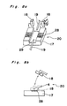
- Figs. 10a and 10b show another example of reinforcement of the joints 5.
- a heat-shrinkable tube 6 containing a reinforcing core 7 and hot-melt adhesive 8 is beforehand passed around one of the two sets of the coated optical fibers 1 as shown by the solid lines and is, after collective fusion splicing of the exposed fiber end portions 4, displaced to the position shown by the broken lines, at which the heat-shrinkable tube 6 embraces the joints 5.
- the heat-shrinkable tube 6 is heated by the heating coil 33 such that the hot-melt adhesive 8 is melted and thus, the exposed fiber end portions 4 and the reinforcing core 7 are integrally embedded in the hot-melt adhesive 8 as shown in Fig. 10b.
- the method of the present invention is applicable to any type of optical fibers regardless of whether the optical fibers are single-mode optical fibers or multimode optical fibers. It is apparent that the collective fusion splicing method of the present invention is also applicable to a ribbon type multi-fiber optical fiber cable in which a plurality of the coated optical fibers are arranged integrally as referred to earlier. Thus, a branch portion from the coated optical fibers of the ribbon type multi-fiber optical fiber cable to those of a loose tube type multi-fiber optical fiber cable can be made compact in size and can be produced rapidly.
- the apparatus K1 mainly includes a rolled tape (tape feeding means) 44a for feeding an adhesive tape 44 for bonding the coated optical fibers 1 thereto, a tape fixing base (tape fixing means) 46 for fixing the adhesive tape 44 and a pair of positioning slit portions (positioning means) 47 for arranging the coated optical fibers 1.
- a plurality of the coated optical fibers 1 are inserted into the loose tube 2 at random and are integrally held by, for example, a clamp mechanism 43.
- This apparatus K1 is provided along optical axes of the coated optical fibers 1 and the adhesive tape 44 is disposed substantially at right angles to the optical axes of the coated optical fibers 1.
- a fiber fixing member 45 for fixing end portions of the coated optical fibers 1 is provided adjacent to one end of a fixed base 49 remote from the clamp mechanism 43.
- a block 45a of rectangular parallelopiped stands and a double-sided adhesive tape 45b having opposite adhesive faces is bonded to one side face of the block 45a, which extends substantially in parallel with the optical axes of the coated optical fibers 1.
- the clamp mechanism 43 and the fiber fixing member 45 are not essential constituents elements of the apparatus K1 but are subordinate constituent elements of the apparatus K1. Therefore, the clamp mechanism 43 and the fiber fixing member 45 are not necessarily required for the apparatus K1 of the present invention.
- the rolled tape 44a is placed on the tape fixing base 46 so as to be stretched in a direction substantially perpendicular to the optical axes of the coated optical fibers 1 such that an adhesive face of the adhesive tape 44 faces forwardly from the tape fixing base 46.
- the adhesive tape 44 may be a heat-resistant adhesive tape.
- the rolled tape 44a is placed at an upper portion of the tape fixing base 46 but satisfaction of such a requirement is important that the adhesive face of the adhesive tape 44 faces forwardly from the tape fixing base 46 so as to extend in the direction substantially perpendicular to the optical axes of the coated optical fibers 1.
- the rolled tape 44a can also be disposed at a lower portion of the tape fixing base 46.
- the tape fixing base 46 has a flat portion 46a disposed obliquely in the direction substantially perpendicular to the optical axes of the coated optical fibers 1 and a tape support portion 46b for supporting the rolled tape 44a, which is disposed at an upper portion of the tape fixing base 46.
- a fixing member 46c for fixing a distal end portion 44b of the adhesive tape 44 is provided at a lower portion of the tape fixing base 46.
- the fixing member 46c and the tape support portion 46b are, respectively, provided at the upper portion and the lower portion of the tape fixing base 46.
- the flat portion 46a has at least such an area as to enable the coated optical fibers of the ribbon type multi-fiber optical fiber cable to be arranged side by side.
- the fixing member 46c is formed by a magnet and the tape fixing base 46 is made of a magnetic metal such that the distal end portion 44b of the adhesive tape 44 is secured between the fixing member 46c and the tape fixing base 46.
- a pair of the positioning slit portions 47 for arranging the coated optical fibers 1 in parallel with each other at a predetermined interval either in numerical order or according to colors are provided, respectively.
- Each of the positioning slit portions 47 has a slit 47a defined by opposite members 47b and 47c therebetween.
- the slit 47a is so formed as to extend substantially in parallel with the plane of the flat portion 46a of the tape fixing base 46 and a width of the slit 47a is so set as to be slightly larger than the outside diameter of the coated optical fibers 1.
- the width of the slit 47a can be changed if one of the opposite members 47b and 47c is of movable construction. In this case, scatter of size of the coated optical fibers can be dealt with and the apparatus is applicable to the coated optical fibers of various sizes.
- the opposite members 47c can be depressed horizontally in a direction substantially perpendicular to the optical axes of the coated optical fibers 1 by a distal end of a micrometer head 48 as shown in Fig. 12, the width of the slits 47a can be increased. Meanwhile, since the opposite members 47c and the tape fixing base 46 are secured to the fixed base 49, relative position of the opposite members 47c and the tape fixing base 46 does not change.
- the coated optical fibers 1 are inserted into the slit 47a either in numerical order or according to colors such as brown, red, black, etc. Since the opposite members 47c are of movable construction as described above, the width of the slit 47a can be adjusted by screwing the micrometer head 48 in case the coated optical fibers 1 of a larger outside diameter are inserted into the slit 47a.
- Fig. 13a the coated optical fibers 1 are inserted into the slit 47a either in numerical order or according to colors such as brown, red, black, etc. Since the opposite members 47c are of movable construction as described above, the width of the slit 47a can be adjusted by screwing the micrometer head 48 in case the coated optical fibers 1 of a larger outside diameter are inserted into the slit 47a.
- 13b shows a profile a (shown by the two-dot chain line) of the flat portion 46a of the tape fixing base 46 and profiles b and c (shown by the two-dot chain lines) of the opposite members 47b and 47c defining the slit 47a therebetween.
- the coated optical fibers 1 are accommodated between the two-dot chain lines b and c, i.e. in the slit 47a but the two-dot chain line a slightly deviates from the two-dot chain lines b and c.
- the coated optical fibers 1 are so disposed as to be depressed against the flat portion 46a. Therefore, the coated optical fibers 1 can be easily attached to the adhesive tape 44 secured to the flat portion 46a.
- step S101 the 12 coated optical fibers 1 in the loose tube 2 are longitudinally equally arranged at distal ends thereof and are collectively clamped, at a location thereof spaced about 20cm from the distal ends, by the clamp mechanism 43.
- step S102 a first one of the 12 coated optical fibers 1 is selected and is inserted into the two slits 47a.
- the coated optical fiber 1 is slid to the bottom of the slits 47a so as to be in a linear state and a predetermined tensile force is applied to the coated optical fiber 1.
- the coated optical fiber 1 is attached to the adhesive tape 44 at step S104.
- a distal end portion of the coated optical fiber 1 is secured to the fiber fixing member 45 such that the coated optical fiber 1 is kept in a clamping state.
- step S106 If it is found at step S106 that all the 12 coated optical fibers 1 have been arranged side by side in the slits 47a, the distal end portion 44b of the adhesive tape 44 is folded back so as to embrace the 12 coated optical fibers 1 such that the 12 coated optical fibers 1 are clamped by the adhesive tape 44 at step S107. Then, at step S108, an end portion of the adhesive tape 44 is cut so as to be separated from the 12 coated optical fibers 1 embraced by the distal end portion 44b. Subsequently, at step S109, the clamp mechanism 43 is released such that the 12 coated optical fibers 1 are taken out of the slits 47a. At this time, the coated optical fibers 1 are of a construction of a ribbon type multi-fiber optical fiber cable.
- the coated optical fibers can be easily arranged in a predetermined order by the apparatus of simple construction. Therefore, in accordance with the apparatus of the present invention, the coated optical fibers of the loose tube type multi-fiber optical fiber cable can be easily formed into those of the ribbon type multi-fiber optical fiber cable, thereby resulting in rationalization, facilitation and speedup of joining of the coated optical fibers.
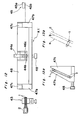
- FIG. 15 there is shown an apparatus K2 for arranging the coated optical fibers 1 in a plane, according to a second embodiment of the present invention.
- the apparatus K2 is applicable to the collective fusion splicing method of the present invention.
- the apparatus K2 is used for arranging 12 coated optical fibers 1 of the loose tube type multi-fiber optical fiber cable 2 into those of the ribbon type multi-fiber optical fiber cable.
- a slot 52 is formed in a longitudinal direction on a fixed base 51 having a shape of rectangular parallelopiped substantially.
- Three pairs of guide pins 53 and 53 ⁇ , 54 and 54 ⁇ and 55 and 55′ stand on the fixed base 51 along and at opposite sides of the slot 52.
- the guide pins 53 and 53 ⁇ are provided at one end of the fixed base 51, while the guides pins 54 and 54 ⁇ and the guide pins 55 and 55 ⁇ are provided relatively adjacent to one another.
- a plurality of V-shaped grooves are formed on a bottom of the slot 52 at an interval equal to that for arranging the coated optical fibers 1. In this case, positional deviation of the coated optical fibers 1 can be obviated and positioning of the coated optical fibers 1 can be performed easily.
- An adhesive tape 57a for securing the coated optical fibers 1 is supplied between the guide pins 54 and 55 and the guide pins 54 ⁇ and 55 ⁇ .
- the adhesive tape 57a may be a heat-resistant adhesive tape and is drawn from a rolled tape 47 contained in a tape case 56.
- the adhesive tape 57a is used for bonding thereto the coated optical fibers 1 arranged in the slot 52 and extends in a direction substantially perpendicular to the longitudinal direction of the slot 52 such that an adhesive face of the adhesive tape 57a confronts the slot 52.
- the tape case 56 is provided such that not only a reel shaft 57b of the tape case 56 extends in parallel with the longitudinal direction of the slot 52 but a tape outlet 56a of the tape case 56 is disposed at one side of the tape case 56 adjacent to the slot 52.
- a clamp mechanism 58 for collectively holding a plurality of the coated optical fibers 1 supplied from the loose tube type multi-fiber optical fiber cable 2 is mounted on the fixed base 51.
- the equiangular plate 59 having 12 angles is mounted on the fixed base 51 so as to be rotated about a vertical rotational axis 59a.
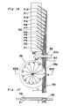
- Figs. 16 and 17 show a state in which the 12 coated optical fibers 1 are temporarily held by the equiangular plate 59.
- a distance between the angle "1" and the rotational axis 59a assumes a value of (L+d) as shown in Fig. 18b and a distance between the angle "2" and the rotational axis 59a assumes a value of (L+2d) as shown in Fig. 18c.
- a distance between the angle "12" and the rotational axis 59a assumes a value of (L+12d) as shown in Figs. 16 and 17. Therefore, when the first coated optical fiber 1 is positioned, the angle "1" is set to a point A shown in Fig.
- the point A is located on a line drawn at right angles to the longitudinal direction of the slot 52 from the rotational axis 59a. At this time, the equiangular plate 59 does not pose any problem in insertion of the second coated optical fiber 1 into the slot 52.
- the equiangular plate 59 may be formed by an eccentric circular plate in which an eccentricity between its rotational axis and its circular center is at least twice the width of the slot 52. Since the circular plate is simpler, in construction, than the equiangular plate 59, the circular plate has such an advantage as its easy manufacture.
- the equiangular plate 59 is provided in the vicinity of the adhesive tape 57a.
- the equiangular plate 59 is is provided adjacent to the guide pins 54 and 54 ⁇ .
- positioning pins P1 to P12 are driven into the slot 52 at predetermined intervals so as to be disposed gradually forwardly in the longitudinal direction from the guide pins 55 and 55 ⁇ and deviate gradually from one side to the other side of the slot 52.
- the positioning pins P1 to P12 are so formed as to become larger in height as the positioning pins P1 to P12 come closer to the adhesive tape 7a such that the coated optical fibers 1 can be easily hung from the corresponding positioning pins P1 to P12.
- the positioning pins P1 to P12 are positioned at an interval of at least 10 times the outside diameter of the coated optical fibers 1, i.e.
- the coated optical fibers 1 can be positioned easily without applying a large bending stress to the coated optical fibers 1.
- Fig. 16 shows a state in which the 12 coated optical fibers 1 are positioned by the positioning pins P1 to P12, respectively.
- a double-sided adhesive tape 62 having opposite adhesive faces is bonded to the fixed base 51.
- the coated optical fibers 1 hung from the respective positioning pins P1 to P12 are temporarily attached to the adhesive tape 62 so as to kept in this state.
- step S201 the 12 coated optical fibers 1 in the loose tube 2 are longitudinally equally arranged at distal ends thereof and are bundled, at a location thereof spaced about 20cm from the distal ends, into a parallel state so as to be collectively held and clamped by the clamp mechanism 58.
- step S203 a first one of the coated optical fibers 1 is selected and is inserted into the slot 52 along the guide pins 53 ⁇ , 54 ⁇ and 55 ⁇ .
- the first coated optical fiber 1 is positioned by hanging the first coated optical fiber 1 from the positioning pin P1. Then, at step S205, an end portion of the first coated optical fiber 1 is attached to the adhesive tape 62 while being slightly stretched so as to be kept in the positioning state.
- step S206 the equiangular plate 59 is rotated so as to set the graduation "1" to the point A such that the first coated optical fiber 1 is retained between the equiangular plate 59 and the slot 52. Furthermore, by repeating the above described steps, the second coated optical fiber 1 is inserted along the first coated optical fiber 1 into the slot 52 and is hung from the positioning pin P2 such that an end portion of the second coated optical fiber 1 is attached to the adhesive tape 62. Subsequently, the graduation "2" of the equiangular plate 59 is set to the point A such that the positioned two coated optical fibers 1 are retained between the equiangular plate 59 and the slot 52 as shown in Fig. 18c.
- the 12 coated optical fibers 1 are clamped in parallel with each other in the slot 52. If it is found at step S207 that all the 12 coated optical fibers 1 have been arranged in the slot 52 either in numerical order or according to colors, the adhesive tape 57a is drawn from the tape case 56 and is attached to upper portions of the 12 coated optical fibers 1 at step S208. Namely, in Fig. 15, the adhesive tape 57a has an adhesive face confronting the fixed base 51.
- step S209 the end portions of the coated optical fibers 1 are removed from the adhesive tape 62 and thus, the coated optical fibers 1 are unclamped by setting the graduation "0" to the point A and releasing the coated optical fibers 1 from the clamp mechanism 58.
- step S210 a distal end portion of the adhesive tape 57a is folded back to a lower side of the coated optical fibers 1 so as to embrace the coated optical fibers 1.
- step S211 an end portion of the adhesive tape 57a is cut so as to be separated from the coated optical fibers 1 embraced by the distal end portion of the adhesive tape 57a.
- a ribbon type multi-fiber optical fiber cable having the 12 coated optical fibers 1 is obtained, thereby resulting in completion of arrangement of the 12 coated optical fibers 1.
- a plurality of the coated optical fibers can be arranged at a predetermined interval and in a predetermined order. Therefore, in accordance with the apparatus of the present invention, the coated optical fibers of the loose tube type multi-fiber optical fiber cable can be easily formed into those of the ribbon type multi-fiber optical fiber cable, thereby resulting in rationalization, facilitation and speedup of joining of the coated optical fibers.
Landscapes
- Physics & Mathematics (AREA)
- Engineering & Computer Science (AREA)
- Plasma & Fusion (AREA)
- General Physics & Mathematics (AREA)
- Optics & Photonics (AREA)
- Mechanical Coupling Of Light Guides (AREA)
Applications Claiming Priority (6)
| Application Number | Priority Date | Filing Date | Title |
|---|---|---|---|
| JP26778/87 | 1987-02-06 | ||
| JP62026778A JPH0660967B2 (ja) | 1987-02-06 | 1987-02-06 | 光フアイバの一括融着接続方法 |
| JP62240218A JPS6481916A (en) | 1987-09-25 | 1987-09-25 | Device for arraying optical fiber |
| JP240217/87 | 1987-09-25 | ||
| JP62240217A JPS6481922A (en) | 1987-09-25 | 1987-09-25 | Device for arraying optical fiber |
| JP240218/87 | 1987-09-25 |
Publications (4)
| Publication Number | Publication Date |
|---|---|
| EP0278423A2 true EP0278423A2 (fr) | 1988-08-17 |
| EP0278423A3 EP0278423A3 (en) | 1990-06-27 |
| EP0278423B1 EP0278423B1 (fr) | 1993-06-02 |
| EP0278423B2 EP0278423B2 (fr) | 1996-10-16 |
Family
ID=27285535
Family Applications (1)
| Application Number | Title | Priority Date | Filing Date |
|---|---|---|---|
| EP88101690A Expired - Lifetime EP0278423B2 (fr) | 1987-02-06 | 1988-02-05 | Dispositif pour l'agencement d'une pluralité de fibres optiques et méthode de soudage collectif par fusion utilisant ce dispositif |
Country Status (7)
| Country | Link |
|---|---|
| US (1) | US4812010A (fr) |
| EP (1) | EP0278423B2 (fr) |
| KR (1) | KR910004713B1 (fr) |
| CN (1) | CN1024221C (fr) |
| CA (1) | CA1303340C (fr) |
| DE (1) | DE3881410T3 (fr) |
| NO (1) | NO176077C (fr) |
Cited By (20)
| Publication number | Priority date | Publication date | Assignee | Title |
|---|---|---|---|---|
| EP0340867A3 (en) * | 1988-05-06 | 1990-08-29 | Philips Patentverwaltung Gmbh | Method and device for mounting a multiplicity of light-guides in a clamping fixture |
| US5046813A (en) * | 1988-09-07 | 1991-09-10 | Fujikura Ltd. | Method and apparatus for aligning a plurality of single-fiber cables, and method of simultaneously fusion-splicing such cables |
| US5170456A (en) * | 1988-09-07 | 1992-12-08 | Fujikura Ltd. | Apparatus for aligning a plurality of single-fiber cables |
| US5546491A (en) * | 1994-06-27 | 1996-08-13 | Siemens Aktiengesellschaft | Method for producing a spliced connection between two groups of light waveguides |
| GB2324167A (en) * | 1997-04-09 | 1998-10-14 | Siemens Ag | Optical waveguide splice protection system |
| ES2122895A1 (es) * | 1996-02-20 | 1998-12-16 | Univ Zaragoza | Acoplador para fibra optica de plastico. |
| EP0893721A1 (fr) * | 1997-07-17 | 1999-01-27 | Litton Systems, Inc. | Dispositif d'interconnexion optique |
| US5933564A (en) * | 1995-11-22 | 1999-08-03 | Litton Systems, Inc. | Optical interconnection apparatus |
| WO2003052474A1 (fr) * | 2001-12-14 | 2003-06-26 | Tyco Electronics Raychem Nv | Procede d'assemblage d'un circuit de fibres optiques |
| EP1408357A1 (fr) | 2002-10-08 | 2004-04-14 | Fujikura Ltd. | Procédé d'alignement axial d'une fibre optique et dispositif associé, et procédé d'épissage par fusion et dispositif associé |
| WO2014060999A1 (fr) * | 2012-10-19 | 2014-04-24 | Tyco Electronics (Shanghai) Co. Ltd. | Machine et procédé pour dénuder thermiquement des câbles optiques |
| EP2787380A1 (fr) * | 2013-04-03 | 2014-10-08 | Tyco Electronics Nederland B.V. | Trieuse de câble automatisé et procédé permettant de trier automatiquement des câbles |
| US20200012047A1 (en) | 2017-03-21 | 2020-01-09 | Corning Research & Development Corporation | Fiber optic cable assembly with thermoplastically overcoated fusion splice, and related method and apparatus |
| US11209594B2 (en) | 2018-09-07 | 2021-12-28 | Corning Incorporated | Cable with overcoated non-coplanar groups of fusion spliced optical fibers, and fabrication method |
| US11347014B2 (en) | 2018-09-07 | 2022-05-31 | Corning Incorporated | Optical fiber fan-out assembly with ribbonized interface for mass fusion splicing, and fabrication method |
| US11353658B2 (en) | 2020-03-31 | 2022-06-07 | Corning Research & Development Corporation | Multi-fiber splice protector, fiber optic cable assembly incorporating same, and fabrication method |
| US11360265B2 (en) | 2019-07-31 | 2022-06-14 | Corning Research & Development Corporation | Fiber optic cable assembly with overlapping bundled strength members, and fabrication method and apparatus |
| US11808983B2 (en) | 2020-11-24 | 2023-11-07 | Corning Research & Development Corporation | Multi-fiber splice protector with compact splice-on furcation housing |
| US11867947B2 (en) | 2021-04-30 | 2024-01-09 | Corning Research & Development Corporation | Cable assembly having routable splice protectors |
| US11886009B2 (en) | 2020-10-01 | 2024-01-30 | Corning Research & Development Corporation | Coating fusion spliced optical fibers and subsequent processing methods thereof |
Families Citing this family (21)
| Publication number | Priority date | Publication date | Assignee | Title |
|---|---|---|---|---|
| DE3735886A1 (de) * | 1987-10-23 | 1989-05-03 | Kabelmetal Electro Gmbh | Verfahren und vorrichtung zum verbinden von aus glas bestehenden lichtwellenleitern |
| US5013345A (en) * | 1987-12-04 | 1991-05-07 | Fujikura Ltd. | Method of fusion-splicing polarization maintaining optical fibers |
| JPH0675023B2 (ja) * | 1988-01-30 | 1994-09-21 | 株式会社フジクラ | 光ファイバの接続損失推定法 |
| US4932747A (en) * | 1989-09-07 | 1990-06-12 | The United States Of America As Represented By The Secretary Of The Navy | Fiber bundle homogenizer and method utilizing same |
| GB9011506D0 (en) * | 1990-05-23 | 1990-07-11 | Bicc Plc | Optical fibre fusion splicing |
| US5207857A (en) * | 1990-05-29 | 1993-05-04 | The Furukawa Electric Co., Ltd. | Forced aligning jig for loose wires |
| GB9104951D0 (en) * | 1991-03-08 | 1991-04-24 | Bicc Plc | Optical fibre fusion splicing |
| GB9117761D0 (en) * | 1991-08-16 | 1991-10-02 | Bicc Plc | Optical fibre splicing |
| WO1994024591A1 (fr) * | 1993-04-19 | 1994-10-27 | Sumitomo Electric Industries, Ltd. | Coupleur de cable optique du type multifibre et procede pour sa production |
| SE504587C2 (sv) * | 1995-10-09 | 1997-03-10 | Ericsson Telefon Ab L M | Fanoutanordning samt förfarande för tillverkning av en sådan |
| EP0901026A1 (fr) * | 1997-08-04 | 1999-03-10 | PIRELLI CAVI E SISTEMI S.p.A. | Procédé de couplage optique de components optiques dans un appareil opto-electronique et appareil construit selon ledit procédé |
| US6332722B1 (en) | 1997-08-04 | 2001-12-25 | Pirelli Cavi E Sistemi S.P.A. | Method for optically connecting optical components in an optoelectronic rig, and optoelectronic rig constructed according to this method |
| US6594437B1 (en) * | 2000-08-15 | 2003-07-15 | Fci Americas Technology, Inc. | Optical fiber separation and regrouping device |
| JP4200383B2 (ja) * | 2002-08-20 | 2008-12-24 | 住友電気工業株式会社 | 線状体のテープ化治具及びテープ化方法 |
| JP4263509B2 (ja) * | 2003-03-14 | 2009-05-13 | 株式会社フジクラ | 光ファイバ把持装置及び光ファイバ突合わせ装置、並びに光ファイバ融着接続装置 |
| US9069143B2 (en) * | 2010-03-16 | 2015-06-30 | Ofs Fitel, Llc | Multifiber connectors for multicore optical fiber cables |
| DE102012205723A1 (de) * | 2012-04-05 | 2013-10-10 | Nokia Siemens Networks Oy | Lichtwellenleiter-ribbonisierungs-vorrichtung und -verfahren |
| TWI565986B (zh) * | 2012-11-13 | 2017-01-11 | 鴻海精密工業股份有限公司 | 光纖固定裝置 |
| US10663666B2 (en) * | 2013-12-05 | 2020-05-26 | United States Of America As Represented By The Secretary Of The Navy | Flexible, low profile kink resistant fiber optic splice tension sleeve |
| EP3923049B1 (fr) * | 2019-02-05 | 2026-01-14 | Sumitomo Electric Optifrontier Co., Ltd. | Dispositif d'épissage par fusion et procédé d'épissage par fusion |
| CN110908038B (zh) * | 2019-12-16 | 2021-05-25 | 江苏永鼎股份有限公司 | 一种大芯数散纤光缆接续工艺 |
Family Cites Families (6)
| Publication number | Priority date | Publication date | Assignee | Title |
|---|---|---|---|---|
| FR2367295A1 (fr) * | 1976-10-05 | 1978-05-05 | Cables De Lyon Geoffroy Delore | Procede et disposit |
| EP0164784A1 (fr) * | 1984-05-23 | 1985-12-18 | Koninklijke Philips Electronics N.V. | Procédé pour la connexion de fibres optiques |
| US4666240A (en) * | 1985-02-01 | 1987-05-19 | Amp Incorporated | Splice organizer for optical cable splices |
| JPS623208A (ja) * | 1985-06-28 | 1987-01-09 | Sumitomo Electric Ind Ltd | 光フアイバの接続方法 |
| JPS6279209U (fr) * | 1985-11-05 | 1987-05-21 | ||
| GB8611361D0 (en) * | 1986-05-09 | 1986-06-18 | Bicc Plc | Splicing optical fibre ribbon |
-
1988
- 1988-02-02 KR KR1019880000937A patent/KR910004713B1/ko not_active Expired
- 1988-02-02 US US07/151,643 patent/US4812010A/en not_active Expired - Lifetime
- 1988-02-04 CA CA000558195A patent/CA1303340C/fr not_active Expired - Lifetime
- 1988-02-05 NO NO880521A patent/NO176077C/no not_active IP Right Cessation
- 1988-02-05 DE DE3881410T patent/DE3881410T3/de not_active Expired - Lifetime
- 1988-02-05 EP EP88101690A patent/EP0278423B2/fr not_active Expired - Lifetime
- 1988-02-06 CN CN88101187A patent/CN1024221C/zh not_active Expired - Lifetime
Cited By (30)
| Publication number | Priority date | Publication date | Assignee | Title |
|---|---|---|---|---|
| EP0340867A3 (en) * | 1988-05-06 | 1990-08-29 | Philips Patentverwaltung Gmbh | Method and device for mounting a multiplicity of light-guides in a clamping fixture |
| US5046813A (en) * | 1988-09-07 | 1991-09-10 | Fujikura Ltd. | Method and apparatus for aligning a plurality of single-fiber cables, and method of simultaneously fusion-splicing such cables |
| US5170456A (en) * | 1988-09-07 | 1992-12-08 | Fujikura Ltd. | Apparatus for aligning a plurality of single-fiber cables |
| EP0358214B1 (fr) * | 1988-09-07 | 1995-12-13 | Fujikura Ltd. | Méthode et dispositif pour l'alignement d'une pluralité de câbles à fibres optiques et méthode de soudure simultanée de ces câbles pour arc électrique |
| US5546491A (en) * | 1994-06-27 | 1996-08-13 | Siemens Aktiengesellschaft | Method for producing a spliced connection between two groups of light waveguides |
| US5933564A (en) * | 1995-11-22 | 1999-08-03 | Litton Systems, Inc. | Optical interconnection apparatus |
| ES2122895A1 (es) * | 1996-02-20 | 1998-12-16 | Univ Zaragoza | Acoplador para fibra optica de plastico. |
| FR2762101A1 (fr) * | 1997-04-09 | 1998-10-16 | Siemens Ag | Protection d'epissure et dispositif de reception de guides d'ondes lumineuses ainsi que dispositif pour inserer les guides d'ondes lumineuses dans la protection d'epissure |
| GB2324167A (en) * | 1997-04-09 | 1998-10-14 | Siemens Ag | Optical waveguide splice protection system |
| US6116793A (en) * | 1997-04-09 | 2000-09-12 | Siemens Aktiengesellschaft | Splice protection device, a receptacle device for light waveguides and an arrangement for placing the light waveguides into the splice protection device |
| GB2324167B (en) * | 1997-04-09 | 2001-03-07 | Siemens Ag | Optical waveguide splice protection system |
| EP0893721A1 (fr) * | 1997-07-17 | 1999-01-27 | Litton Systems, Inc. | Dispositif d'interconnexion optique |
| WO2003052474A1 (fr) * | 2001-12-14 | 2003-06-26 | Tyco Electronics Raychem Nv | Procede d'assemblage d'un circuit de fibres optiques |
| US7151877B2 (en) | 2002-10-08 | 2006-12-19 | Fujikura Ltd. | Optical fiber axial alignment method and related device, and optical fiber fusion splicing method and related device |
| EP1408357A1 (fr) | 2002-10-08 | 2004-04-14 | Fujikura Ltd. | Procédé d'alignement axial d'une fibre optique et dispositif associé, et procédé d'épissage par fusion et dispositif associé |
| WO2014060999A1 (fr) * | 2012-10-19 | 2014-04-24 | Tyco Electronics (Shanghai) Co. Ltd. | Machine et procédé pour dénuder thermiquement des câbles optiques |
| EP2787380A1 (fr) * | 2013-04-03 | 2014-10-08 | Tyco Electronics Nederland B.V. | Trieuse de câble automatisé et procédé permettant de trier automatiquement des câbles |
| WO2014161750A1 (fr) * | 2013-04-03 | 2014-10-09 | Te Connectivity Nederland Bv | Distributeur automatique de trieur de câbles et procédé de tri automatique de câbles |
| CN105264417A (zh) * | 2013-04-03 | 2016-01-20 | 泰科电子连接荷兰公司 | 用于自动地分拣电缆的电缆自动分拣机和方法 |
| US20200012047A1 (en) | 2017-03-21 | 2020-01-09 | Corning Research & Development Corporation | Fiber optic cable assembly with thermoplastically overcoated fusion splice, and related method and apparatus |
| US11131811B2 (en) | 2017-03-21 | 2021-09-28 | Corning Research & Development Corporation | Fiber optic cable assembly with thermoplastically overcoated fusion splice, and related method and apparatus |
| US11561344B2 (en) | 2017-03-21 | 2023-01-24 | Corning Research & Development Corporation | Fiber optic cable assembly with thermoplastically overcoated fusion splice, and related method and apparatus |
| US11347014B2 (en) | 2018-09-07 | 2022-05-31 | Corning Incorporated | Optical fiber fan-out assembly with ribbonized interface for mass fusion splicing, and fabrication method |
| US11209594B2 (en) | 2018-09-07 | 2021-12-28 | Corning Incorporated | Cable with overcoated non-coplanar groups of fusion spliced optical fibers, and fabrication method |
| US11360265B2 (en) | 2019-07-31 | 2022-06-14 | Corning Research & Development Corporation | Fiber optic cable assembly with overlapping bundled strength members, and fabrication method and apparatus |
| US11774677B2 (en) | 2019-07-31 | 2023-10-03 | Corning Research & Development Corporation | Fiber optic cable assembly with overlapping bundled strength members, and fabrication method and apparatus |
| US11353658B2 (en) | 2020-03-31 | 2022-06-07 | Corning Research & Development Corporation | Multi-fiber splice protector, fiber optic cable assembly incorporating same, and fabrication method |
| US11886009B2 (en) | 2020-10-01 | 2024-01-30 | Corning Research & Development Corporation | Coating fusion spliced optical fibers and subsequent processing methods thereof |
| US11808983B2 (en) | 2020-11-24 | 2023-11-07 | Corning Research & Development Corporation | Multi-fiber splice protector with compact splice-on furcation housing |
| US11867947B2 (en) | 2021-04-30 | 2024-01-09 | Corning Research & Development Corporation | Cable assembly having routable splice protectors |
Also Published As
| Publication number | Publication date |
|---|---|
| US4812010A (en) | 1989-03-14 |
| NO880521D0 (no) | 1988-02-05 |
| CA1303340C (fr) | 1992-06-16 |
| EP0278423B1 (fr) | 1993-06-02 |
| NO176077B (no) | 1994-10-17 |
| NO176077C (no) | 1995-01-25 |
| EP0278423B2 (fr) | 1996-10-16 |
| DE3881410T3 (de) | 1997-04-10 |
| DE3881410D1 (de) | 1993-07-08 |
| CN88101187A (zh) | 1988-08-31 |
| EP0278423A3 (en) | 1990-06-27 |
| KR910004713B1 (ko) | 1991-07-10 |
| DE3881410T2 (de) | 1993-11-18 |
| NO880521L (no) | 1988-08-08 |
| CN1024221C (zh) | 1994-04-13 |
| KR880010342A (ko) | 1988-10-08 |
Similar Documents
| Publication | Publication Date | Title |
|---|---|---|
| EP0278423B1 (fr) | Dispositif pour l'agencement d'une pluralité de fibres optiques et méthode de soudage collectif par fusion utilisant ce dispositif | |
| US11428889B2 (en) | Tooling and method for manufacturing a fiber optic array | |
| US4980007A (en) | Methods of fabricating an optical fiber ribbon | |
| JPH11506546A (ja) | 光ファイバリボンケーブルおよびその製造方法 | |
| US4123137A (en) | Optical fiber arrangement for splicing fibers secured to ribbonlike tape | |
| EP4163686A1 (fr) | Procédés et ensembles d'épissure de masse de fibre optique | |
| JP3125030B2 (ja) | 光ファイバの端末処理台とそれを使用する光ファイバの処理方法 | |
| CA1334478C (fr) | Appareil pour positionner une multiplicite de fibres optiques gainees | |
| JP4878833B2 (ja) | 光ファイバホルダ及び一括融着接続方法 | |
| EP4109159A1 (fr) | Cassette de multiplexage par répartition en longueur d'onde pour un réseau à fibres optiques et son procédé de fabrication | |
| JP2685153B2 (ja) | 光ファイバv溝台 | |
| JP3710538B2 (ja) | 光ファイバ接続器付きの多心単心変換用光ファイバ | |
| JPH10332976A (ja) | 光ファイバ心線の接続方法 | |
| JPH0827413B2 (ja) | 多心光ファイバの一括融着接続方法 | |
| JP2011002858A (ja) | 一括融着接続方法 | |
| JPH09230158A (ja) | 光ファイバの配列構造 | |
| JPS62254108A (ja) | 多対光フアイバテ−プの心線融着接続装置 | |
| CA1052549A (fr) | Appareils et methodes pour le soudage des fibres optiques | |
| JPH07128539A (ja) | 光フアイバの接続方法および光フアイバ接続部の集線補強構造ならびに光フアイバ接続部への荷重試験方法 | |
| JPH05181032A (ja) | 高強度接続のための均一薄膜被覆用ファイバクランプ装置 | |
| WO2003104873A1 (fr) | Plaque d'epissure pour fibres optiques | |
| JPS61245114A (ja) | 光フアイバの融着接続装置 | |
| JPH07159644A (ja) | 融着接続機 | |
| JPH0440685B2 (fr) | ||
| JPH07119861B2 (ja) | 擬似リボン心線の製造方法及び心線整列装置 |
Legal Events
| Date | Code | Title | Description |
|---|---|---|---|
| PUAI | Public reference made under article 153(3) epc to a published international application that has entered the european phase |
Free format text: ORIGINAL CODE: 0009012 |
|
| AK | Designated contracting states |
Kind code of ref document: A2 Designated state(s): BE DE FR GB IT NL SE |
|
| PUAL | Search report despatched |
Free format text: ORIGINAL CODE: 0009013 |
|
| RHK1 | Main classification (correction) |
Ipc: C03B 37/14 |
|
| AK | Designated contracting states |
Kind code of ref document: A3 Designated state(s): BE DE FR GB IT NL SE |
|
| 17P | Request for examination filed |
Effective date: 19900820 |
|
| 17Q | First examination report despatched |
Effective date: 19911104 |
|
| GRAA | (expected) grant |
Free format text: ORIGINAL CODE: 0009210 |
|
| AK | Designated contracting states |
Kind code of ref document: B1 Designated state(s): BE DE FR GB IT NL SE |
|
| REF | Corresponds to: |
Ref document number: 3881410 Country of ref document: DE Date of ref document: 19930708 |
|
| ITF | It: translation for a ep patent filed | ||
| ET | Fr: translation filed | ||
| PLBI | Opposition filed |
Free format text: ORIGINAL CODE: 0009260 |
|
| PLBI | Opposition filed |
Free format text: ORIGINAL CODE: 0009260 |
|
| PLAB | Opposition data, opponent's data or that of the opponent's representative modified |
Free format text: ORIGINAL CODE: 0009299OPPO |
|
| PLAB | Opposition data, opponent's data or that of the opponent's representative modified |
Free format text: ORIGINAL CODE: 0009299OPPO |
|
| 26 | Opposition filed |
Opponent name: KABELMETAL ELECTRO GMBH Effective date: 19940219 |
|
| 26 | Opposition filed |
Opponent name: KABELMETAL ELECTRO GMBH Effective date: 19940219 Opponent name: SIEMENS AKTIENGESELLSCHAFT ABT. ZFE GR PA 7 Effective date: 19940301 |
|
| R26 | Opposition filed (corrected) |
Opponent name: KABELMETAL ELECTRO GMBH * 940301 SIEMENS AKTIENGES Effective date: 19940219 |
|
| R26 | Opposition filed (corrected) |
Opponent name: KABELMETAL ELECTRO GMBH * 940301 SIEMENS AKTIENGES Effective date: 19940219 |
|
| NLR1 | Nl: opposition has been filed with the epo |
Opponent name: SIEMENS AKTIENGESELLSCHAFT ABT. ZFE GR PA 7 Opponent name: KABELMETAL ELECTRO GMBH. |
|
| EAL | Se: european patent in force in sweden |
Ref document number: 88101690.1 |
|
| PLAB | Opposition data, opponent's data or that of the opponent's representative modified |
Free format text: ORIGINAL CODE: 0009299OPPO |
|
| R26 | Opposition filed (corrected) |
Opponent name: KABELMETAL ELECTRO GMBH * 940301 SIEMENS AKTIENGES Effective date: 19940219 |
|
| NLR1 | Nl: opposition has been filed with the epo |
Opponent name: SIEMENS AKTIENGESELLSCHAFT ABT. ZFE GR PA 7 Opponent name: KABELMETAL ELECTRO GMBH |
|
| PLAW | Interlocutory decision in opposition |
Free format text: ORIGINAL CODE: EPIDOS IDOP |
|
| PLAW | Interlocutory decision in opposition |
Free format text: ORIGINAL CODE: EPIDOS IDOP |
|
| PUAH | Patent maintained in amended form |
Free format text: ORIGINAL CODE: 0009272 |
|
| STAA | Information on the status of an ep patent application or granted ep patent |
Free format text: STATUS: PATENT MAINTAINED AS AMENDED |
|
| 27A | Patent maintained in amended form |
Effective date: 19961016 |
|
| AK | Designated contracting states |
Kind code of ref document: B2 Designated state(s): BE DE FR GB IT NL SE |
|
| NLR2 | Nl: decision of opposition | ||
| ITF | It: translation for a ep patent filed | ||
| ET3 | Fr: translation filed ** decision concerning opposition | ||
| NLR3 | Nl: receipt of modified translations in the netherlands language after an opposition procedure | ||
| REG | Reference to a national code |
Ref country code: GB Ref legal event code: IF02 |
|
| PGFP | Annual fee paid to national office [announced via postgrant information from national office to epo] |
Ref country code: SE Payment date: 20030205 Year of fee payment: 16 |
|
| PGFP | Annual fee paid to national office [announced via postgrant information from national office to epo] |
Ref country code: NL Payment date: 20030226 Year of fee payment: 16 |
|
| PGFP | Annual fee paid to national office [announced via postgrant information from national office to epo] |
Ref country code: BE Payment date: 20030425 Year of fee payment: 16 |
|
| PG25 | Lapsed in a contracting state [announced via postgrant information from national office to epo] |
Ref country code: SE Free format text: LAPSE BECAUSE OF NON-PAYMENT OF DUE FEES Effective date: 20040206 |
|
| PG25 | Lapsed in a contracting state [announced via postgrant information from national office to epo] |
Ref country code: BE Free format text: LAPSE BECAUSE OF NON-PAYMENT OF DUE FEES Effective date: 20040228 |
|
| BERE | Be: lapsed |
Owner name: *SUMITOMO ELECTRIC INDUSTRIES LTD Effective date: 20040228 |
|
| PG25 | Lapsed in a contracting state [announced via postgrant information from national office to epo] |
Ref country code: NL Free format text: LAPSE BECAUSE OF NON-PAYMENT OF DUE FEES Effective date: 20040901 |
|
| EUG | Se: european patent has lapsed | ||
| NLV4 | Nl: lapsed or anulled due to non-payment of the annual fee |
Effective date: 20040901 |
|
| PGFP | Annual fee paid to national office [announced via postgrant information from national office to epo] |
Ref country code: GB Payment date: 20070131 Year of fee payment: 20 |
|
| PGFP | Annual fee paid to national office [announced via postgrant information from national office to epo] |
Ref country code: DE Payment date: 20070201 Year of fee payment: 20 |
|
| PGFP | Annual fee paid to national office [announced via postgrant information from national office to epo] |
Ref country code: IT Payment date: 20070622 Year of fee payment: 20 |
|
| REG | Reference to a national code |
Ref country code: GB Ref legal event code: PE20 |
|
| PGFP | Annual fee paid to national office [announced via postgrant information from national office to epo] |
Ref country code: FR Payment date: 20070208 Year of fee payment: 20 |
|
| PG25 | Lapsed in a contracting state [announced via postgrant information from national office to epo] |
Ref country code: GB Free format text: LAPSE BECAUSE OF EXPIRATION OF PROTECTION Effective date: 20080204 |