EP0281773B1 - Abstimmbares Mikrowellenfilter - Google Patents
Abstimmbares Mikrowellenfilter Download PDFInfo
- Publication number
- EP0281773B1 EP0281773B1 EP88101782A EP88101782A EP0281773B1 EP 0281773 B1 EP0281773 B1 EP 0281773B1 EP 88101782 A EP88101782 A EP 88101782A EP 88101782 A EP88101782 A EP 88101782A EP 0281773 B1 EP0281773 B1 EP 0281773B1
- Authority
- EP
- European Patent Office
- Prior art keywords
- filter
- ground
- variable capacitance
- diodes
- filter according
- Prior art date
- Legal status (The legal status is an assumption and is not a legal conclusion. Google has not performed a legal analysis and makes no representation as to the accuracy of the status listed.)
- Expired - Lifetime
Links
Images

Classifications
-
- H—ELECTRICITY
- H01—ELECTRIC ELEMENTS
- H01P—WAVEGUIDES; RESONATORS, LINES, OR OTHER DEVICES OF THE WAVEGUIDE TYPE
- H01P1/00—Auxiliary devices
- H01P1/20—Frequency-selective devices, e.g. filters
- H01P1/201—Filters for transverse electromagnetic waves
- H01P1/203—Strip line filters
Definitions
- the present invention relates to a tunable filter, in particular in the band from 800 to 1800 MHz.
- the signal received at the antenna of the earth station is in the bands 10.95-11.7 GHz or 12.25-12.75 GHz or 11.7-12.5 GHz etc ...
- a first stage transposes these bands to the RF (radio frequency) bands 950-1700 MHz, 950-1450 MHz, 950-1750 MHz, respectively.
- a second transposition brings these frequencies around an intermediate frequency, or IF, of a few hundred MHz, for example 450 MHz.
- Each channel in the radio frequency band, or RF is a few tens of MHz wide.
- the role of the tunable filter is to transmit only the channel chosen in the total RF input band.
- the rejection of the local oscillator frequencies, or OL, of the last transposition, of the image frequencies and of the mixing products are clearly improved.
- the document EP-0138438 describes a tunable microwave filter which comprises two branches of the same type which, at each end, are connected to ground and which each comprise, connected in series, a fixed inductance, a first adjustable inductance, a first diode with variable capacitance, a filter for high frequencies formed by a series resonance circuit comprising a second diode with variable capacitance and a second variable inductance, and a coupling element comprising a series inductance between the input point and the output point of the filter.
- the object of the invention is to overcome this drawback.
- a tunable microwave filter comprising two branches of the same type each connected at the two ends to ground and each comprising, connected in series: the second end, grounded, a first and a second diode with variable capacity, a connection line, and the first end, grounded, the diodes being controlled by a DC signal, said filter being arranged on the first face of a planar substrate, characterized in that the line of connection is a microstrip line, and in that the microwave input and output are connected to the common points between the microstrip line and the second variable capacity diode of the first and second branch respectively by a symmetrical adapter
- Such a filter has the great advantage of being able to be easily produced in a reproducible manner and therefore of allowing automatic mounting. The cost price of such a filter is therefore very low; it can therefore be used in the case of reception for satellite links, intended for a large audience.
- the filter of the invention is produced on a substrate, the second face of which is completely metallized and forms a ground plane, the ground points being produced by metallized holes.
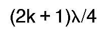
- the filter of the invention is such that the DC voltage supply for each branch is produced by means of an RC filter, this DC voltage supply being connected to the common point of the two variable capacity diodes by a first microstrip line in length (2k + 1) ⁇ / 4 and by the resistance of the RC filter, and at the ground end of the first variable capacitance diode by the capacity of the RC filter; a second microstrip line, connecting the two branches to the DC voltage source, such that the total length of the first and second line is (2k '+ 1) ⁇ / 4 ; k and k 'being any integers.
- variable capacitance diodes are arranged in holes drilled in the substrate; which allows for great positioning accuracy.
- This figure represents a substrate 8 on the first face 9 of which is the filter of the invention.
- This consists of two symmetrical parts or branches 10 (10A) with respect to an axis ⁇ located on the face 9 of this substrate 8.
- This adaptation line 17 (17A) constitutes in the first part (10), the input to which the microwave signal E is connected. It constitutes for the second part (10A) the output on which the microwave signal S is obtained in output of the inventive filter.
- the two lines 11 and 11A of the two parts 10 and 10A of the filter of the invention are coupled together and connected at their end by a section of line 20 itself connected to the ground 22.
- the midpoint of the two varicaps 12A and 13A of the second part is connected to the DC voltage source V via a line 21 such that the length 21 + 14A is equal to (2k '+ 1) ⁇ / 4 .
- the substrate is completely metallized on its second face.
- the ground points are therefore metallized holes 22 and 24.
- Varicaps 12 (12A) and 13 (13A) are arranged in positioning holes 220 (220A) and 23 (23A).
- the structure of the filter of the invention is produced in microstrip technique and the substrate used is for example made of epoxy glass; which is a factor in reducing the cost price.
- the filter is tuned by modifying the DC voltage V applied to varicaps 12, 13, 12A and 13A. These varicaps are for example therefore cheaper than varicaps in AsGa.
- the insulation capacities 16 (16A) as well as the resistors 15 (15A) have the role of bringing to the level of the junction of the two varicaps 12 and 13 (12A and 13A) an infinite impedance for the microwave frequencies considered: these are "surface mount components” (CMS); which allows automatic serial production of the filter of the invention and therefore a reduction in the cost price.
- CMS surface mount components
- the varicaps are housed in circular holes drilled in the substrate to allow better reproducibility of the assembly, so the lengths of the connection tails are not very variable from one assembly to another.
- the filter of the invention is therefore a two-pole filter in which each resonator is composed of a line, two varicaps, and chokes due to the connection tails of the varicaps.
- the coupling between the two resonators takes place at the level of the lines: the coupling between the two lines 11 and 11A depends on their thickness, their spacing and their length.
- the coupling between resonators depends on the operating frequency. Due to the impedance inversions, the necessary filtering function would not be broadband, which would introduce the deterioration of the adaptation in the tuning band according to the voltage applied to the varicaps.
- the purpose of the adapters 18, 19 and 18A, 19A is to overcome this drawback: the elements of these symmetrical adaptations in fact make it possible to obtain a broadband adaptation which is preserved practically throughout the frequency band considered.
- Varicaps can be used whose capacity can, for example, vary from 18 pF to 2pF for a voltage V varying from 0 to 24 Volts (at 500 KHz).
- the capacity ratio which is then 9, limits the band in which the filter is adjustable. It is possible, by increasing this ratio, to obtain filters adjustable over a wider band.
Landscapes
- Physics & Mathematics (AREA)
- Electromagnetism (AREA)
- Control Of Motors That Do Not Use Commutators (AREA)
Claims (6)
- Abstimmbares Mikrowellenfilter mit zwei Zweigen gleichen Typs, von denen jeder mit beiden Enden (22, 24) an Masse angeschlossen ist und jeweils in Reihenschaltung aufweist: das zweite Ende (24) an Masse gelegt, eine erste (13, 13A) und eine zweite Diode (12, 12A) mit veränderlicher Kapazität, eine Verbindungsleitung (11, 11A), und das erste Ende (22) an Masse gelegt, wobei die Dioden von einem Gleichstromsignal (V) angesteuert werden und das Filter auf der ersten Seite (9) eines ebenen Substrats (8) angeordnet ist, dadurch gekennzeichnet, daß die Verbindungsleitung (11, 11A) eine Mikrobandleitung ist und daß der Mikrowelleneingang (E) bzw. der Mikrowellenausgang (S) mit dem gemeinsamen Punkt zwischen der Mikrobandleitung (11, 11A) und der zweiten Diode mit veränderlicher Kapazität (12, 12A) des ersten bzw. des zweiten Zweigs über einen symmetrischen Adapter (18, 19 und 18A, 19A) verbunden ist.
- Filter nach Anspruch 1, dadurch gekennzeichnet, daß die zweite Seite des Substrats vollständig metallisiert ist und eine Erdungsfläche bildet, wobei die Erdungspunkte (22, 24) aus metallisierten Löchern bestehen.
- Filter nach Anspruch 1 oder 2, dadurch gekennzeichnet, daß die Gleichspannungsversorgung (V) jedes Zweigs über ein RC-Filter (15, 16 und 15A, 16A) erfolgt.
- Filter nach Anspruch 3, dadurch gekennzeichnet, daß die Gleichspannungsversorgung (V) an den gemeinsamen Punkt der beiden Dioden veränderlicher Kapazität (12, 13 und 12A, 13A) über eine erste Mikrobandleitung (12A, 14) mit der Länge

- Filter nach Anspruch 1, dadurch gekennzeichnet, daß jeder Adapter aus einem zentralen Arm (19, 19A) und zwei Seitenarmen (18, 18A) besteht, die relativ zum zentralen Arm zwei parallele Arme bilden.
- Filter nach einem beliebigen der vorhergehenden Ansprüche, dadurch gekennzeichnet, daß die Dioden mit veränderlicher Kapazität (12, 12A und 13, 13A) in den in das Substrat gebohrten Löchern (22, 22A und 13, 13A) angeordnet sind und so sehr genau positioniert werden könne.
Applications Claiming Priority (2)
| Application Number | Priority Date | Filing Date | Title |
|---|---|---|---|
| FR8701718 | 1987-02-11 | ||
| FR8701718A FR2610765B1 (fr) | 1987-02-11 | 1987-02-11 | Filtre hyperfrequence accordable |
Publications (2)
| Publication Number | Publication Date |
|---|---|
| EP0281773A1 EP0281773A1 (de) | 1988-09-14 |
| EP0281773B1 true EP0281773B1 (de) | 1992-09-30 |
Family
ID=9347810
Family Applications (1)
| Application Number | Title | Priority Date | Filing Date |
|---|---|---|---|
| EP88101782A Expired - Lifetime EP0281773B1 (de) | 1987-02-11 | 1988-02-08 | Abstimmbares Mikrowellenfilter |
Country Status (5)
| Country | Link |
|---|---|
| US (1) | US4806890A (de) |
| EP (1) | EP0281773B1 (de) |
| JP (1) | JPH01132201A (de) |
| DE (1) | DE3874916T2 (de) |
| FR (1) | FR2610765B1 (de) |
Families Citing this family (12)
| Publication number | Priority date | Publication date | Assignee | Title |
|---|---|---|---|---|
| CA1278106C (en) * | 1988-11-02 | 1990-12-18 | Gordon Glen Rabjohn | Tunable microwave wafer probe |
| JPH02152302A (ja) * | 1988-12-02 | 1990-06-12 | Fujitsu Ltd | 2倍波阻止回路 |
| FR2652211A1 (fr) * | 1989-09-15 | 1991-03-22 | Alcatel Transmission | Resonateur hyperfrequence actif et filtre actif utilisant ce resonateur. |
| FR2679702A1 (fr) * | 1991-07-23 | 1993-01-29 | Thomson Csf | Element semi-conducteur a capacite variable pour circuit integre en micro-ondes et circuit integre equipe d'au moins un tel element. |
| ES2403019B1 (es) * | 2011-10-07 | 2014-03-11 | Universidad Politécnica De Valencia | Filtro de microondas sintonizable en tecnología de montaje superficial basado en cavidades resonantes coaxiales integradas en substrato |
| CN104810596A (zh) * | 2015-04-29 | 2015-07-29 | 清华大学 | 多模谐振器及其双频带滤波器 |
| CN106848600B (zh) * | 2016-12-30 | 2019-10-11 | 广东通宇通讯股份有限公司 | 超宽带水平极化水平全向天线 |
| CN110247143B (zh) * | 2019-06-19 | 2023-12-19 | 南京信息工程大学 | 一种具有可切换和可调谐的微带带通滤波器 |
| CN114552152B (zh) * | 2022-04-06 | 2022-12-27 | 成都美数科技有限公司 | 一种多模超宽带滤波器及其设计方法 |
| PL446023A1 (pl) * | 2023-09-04 | 2025-03-10 | Politechnika Śląska | Układ dwuobwodowego, przestrajanego, planarnego mikrofalowego filtru pasmowoprzepustowego o regulowanej szerokości pasma |
| PL446024A1 (pl) * | 2023-09-04 | 2025-03-10 | Politechnika Śląska | Układ dwuobwodowego, przestrajanego, planarnego, mikrofalowego filtru pasmowoprzepustowego sprzężonego pojemnościowo |
| PL248903B1 (pl) * | 2023-09-04 | 2026-02-09 | Politechnika Slaska Im Wincent | Układ dwuobwodowego, przestrajanego, planarnego mikrofalowego filtru pasmowoprzepustowego |
Family Cites Families (11)
| Publication number | Priority date | Publication date | Assignee | Title |
|---|---|---|---|---|
| US2915716A (en) * | 1956-10-10 | 1959-12-01 | Gen Dynamics Corp | Microstrip filters |
| FR1523984A (fr) * | 1967-05-25 | 1968-05-03 | Fernsehgeratewerke Stassfurt V | Dispositif de couplage conducteur pouvant être accordé pour oscillations électriques de haute fréquence |
| US3530411A (en) * | 1969-02-10 | 1970-09-22 | Bunker Ramo | High frequency electronic circuit structure employing planar transmission lines |
| GB1457806A (en) * | 1974-03-04 | 1976-12-08 | Mullard Ltd | Semiconductor device manufacture |
| US4023125A (en) * | 1975-10-17 | 1977-05-10 | General Electric Company | Printed broadband rf bias circuits |
| US4031488A (en) * | 1976-04-05 | 1977-06-21 | The United States Of America As Represented By The Secretary Of The Navy | Multiple polarization switch |
| US4211987A (en) * | 1977-11-30 | 1980-07-08 | Harris Corporation | Cavity excitation utilizing microstrip, strip, or slot line |
| US4500854A (en) * | 1981-04-20 | 1985-02-19 | John Fluke Mfg. Co., Inc. | Voltage-controlled RF oscillator employing wideband tunable LC resonator |
| US4468644A (en) * | 1982-09-23 | 1984-08-28 | General Instrument Corp. | Tunable reject filter for radar warning receiver |
| US4619001A (en) * | 1983-08-02 | 1986-10-21 | Matsushita Electric Industrial Co., Ltd. | Tuning systems on dielectric substrates |
| FI67980C (fi) * | 1983-10-13 | 1985-06-10 | Salora Oy | Koppling foer ett foer mikrovaogsfrekvenser avstaembart filtersamt foerverkligande av densamma |
-
1987
- 1987-02-11 FR FR8701718A patent/FR2610765B1/fr not_active Expired
-
1988
- 1988-02-08 EP EP88101782A patent/EP0281773B1/de not_active Expired - Lifetime
- 1988-02-08 DE DE8888101782T patent/DE3874916T2/de not_active Expired - Fee Related
- 1988-02-08 JP JP8827386A patent/JPH01132201A/ja active Pending
- 1988-02-10 US US07/154,409 patent/US4806890A/en not_active Expired - Lifetime
Also Published As
| Publication number | Publication date |
|---|---|
| FR2610765A1 (fr) | 1988-08-12 |
| FR2610765B1 (fr) | 1989-02-17 |
| JPH01132201A (ja) | 1989-05-24 |
| DE3874916D1 (de) | 1992-11-05 |
| EP0281773A1 (de) | 1988-09-14 |
| US4806890A (en) | 1989-02-21 |
| DE3874916T2 (de) | 1993-02-18 |
Similar Documents
| Publication | Publication Date | Title |
|---|---|---|
| EP0117178B1 (de) | Mikrowellenfilter mit linienförmigen Resonatoren | |
| EP0012093B1 (de) | Verteilter Mikrowellenverstärker und diesen Verstärker enthaltende Verstärkervorrichtung | |
| EP0281773A1 (de) | Abstimmbares Mikrowellenfilter | |
| EP0098192B1 (de) | Multiplexanordnung zum Zusammenfügen von zwei Frequenzbändern | |
| EP0888647A1 (de) | Wendelantenne mit integrierter breitbandspeisung und verfahren zu deren herstellung | |
| FR2681729A1 (fr) | Circuit integre micro-onde hybride. | |
| EP2178152A1 (de) | Elektronische Umschaltvorrichtung für Hochfrequenzsignale | |
| EP2202838B1 (de) | Kompakt geschalteter MEMS-Kondensator | |
| FR2578123A1 (fr) | Reseau d'accouplement entre etages a bande changee comprenant un condensateur couple cote haut | |
| EP2652835A1 (de) | Aktives bandstopp-filter | |
| FR2653615A1 (fr) | Cellule de filtrage et filtre correspondant. | |
| EP0649571B1 (de) | Bandpassfilter mit gekoppelten resonatoren | |
| EP0563370A1 (de) | Halbleitergerät mit mehreren funktionellen Blöcken, jeder Block mit einer Gleichspannungsverteilungsleitung. | |
| FR2678450A1 (fr) | Dispositif de filtrage coupe-bande hyperfrequence. | |
| FR2509535A1 (fr) | Filtre hyperfrequence comportant des troncons de lignes couples et des moyens de reglage | |
| EP0013223B1 (de) | Vorrichtung zur Unterdrückung von Oberschwingungen für einen Radiosender | |
| EP0736971A1 (de) | Kerbfilter mit variabler Sperrfrequenz | |
| FR2774216A1 (fr) | Module a hautes frequences pour communications | |
| EP0221608A1 (de) | Linear frequenzmodulierter Mikrowellenoszillator mit einem hohen externen Gütefaktor | |
| EP0337825B1 (de) | Mikrowellensperrfilter in Mikrostreifenausführung | |
| EP0326498A1 (de) | Resonanzschaltung und Filter mit dergleichen | |
| FR2494929A1 (fr) | Oscillateur hyperfrequence a transistor, accordable par tension | |
| FR2778288A1 (fr) | Filtre passe-bande accordable | |
| EP0654845A1 (de) | Anpassbares Dipolstrahlerelement in gedruckter Schaltungstechnik, Verfahren zur Einstellung der Anpassung und entsprechende Gruppenantenne | |
| FR2496997A1 (fr) | Dispositif de reglage de l'accord d'une ligne de transmission resonnante, ligne de transmission et filtre de bande hyperfrequence munis de tels dispositifs. |
Legal Events
| Date | Code | Title | Description |
|---|---|---|---|
| PUAI | Public reference made under article 153(3) epc to a published international application that has entered the european phase |
Free format text: ORIGINAL CODE: 0009012 |
|
| AK | Designated contracting states |
Kind code of ref document: A1 Designated state(s): DE FR GB IT NL SE |
|
| 17P | Request for examination filed |
Effective date: 19890309 |
|
| RAP1 | Party data changed (applicant data changed or rights of an application transferred) |
Owner name: ALCATEL TRANSMISSION PAR FAISCEAUX HERTZIENS A.T.F |
|
| 17Q | First examination report despatched |
Effective date: 19910423 |
|
| RAP1 | Party data changed (applicant data changed or rights of an application transferred) |
Owner name: ALCATEL TELSPACE |
|
| GRAA | (expected) grant |
Free format text: ORIGINAL CODE: 0009210 |
|
| AK | Designated contracting states |
Kind code of ref document: B1 Designated state(s): DE FR GB IT NL SE |
|
| GBT | Gb: translation of ep patent filed (gb section 77(6)(a)/1977) | ||
| REF | Corresponds to: |
Ref document number: 3874916 Country of ref document: DE Date of ref document: 19921105 |
|
| ITF | It: translation for a ep patent filed | ||
| PGFP | Annual fee paid to national office [announced via postgrant information from national office to epo] |
Ref country code: FR Payment date: 19921230 Year of fee payment: 6 |
|
| PGFP | Annual fee paid to national office [announced via postgrant information from national office to epo] |
Ref country code: GB Payment date: 19930104 Year of fee payment: 6 |
|
| PGFP | Annual fee paid to national office [announced via postgrant information from national office to epo] |
Ref country code: SE Payment date: 19930122 Year of fee payment: 6 |
|
| PGFP | Annual fee paid to national office [announced via postgrant information from national office to epo] |
Ref country code: DE Payment date: 19930217 Year of fee payment: 6 |
|
| PGFP | Annual fee paid to national office [announced via postgrant information from national office to epo] |
Ref country code: NL Payment date: 19930228 Year of fee payment: 6 |
|
| PLBE | No opposition filed within time limit |
Free format text: ORIGINAL CODE: 0009261 |
|
| STAA | Information on the status of an ep patent application or granted ep patent |
Free format text: STATUS: NO OPPOSITION FILED WITHIN TIME LIMIT |
|
| 26N | No opposition filed | ||
| PG25 | Lapsed in a contracting state [announced via postgrant information from national office to epo] |
Ref country code: GB Effective date: 19940208 |
|
| PG25 | Lapsed in a contracting state [announced via postgrant information from national office to epo] |
Ref country code: SE Effective date: 19940209 |
|
| PG25 | Lapsed in a contracting state [announced via postgrant information from national office to epo] |
Ref country code: NL Effective date: 19940901 |
|
| GBPC | Gb: european patent ceased through non-payment of renewal fee |
Effective date: 19940208 |
|
| NLV4 | Nl: lapsed or anulled due to non-payment of the annual fee | ||
| PG25 | Lapsed in a contracting state [announced via postgrant information from national office to epo] |
Ref country code: FR Effective date: 19941031 |
|
| PG25 | Lapsed in a contracting state [announced via postgrant information from national office to epo] |
Ref country code: DE Effective date: 19941101 |
|
| REG | Reference to a national code |
Ref country code: FR Ref legal event code: ST |
|
| EUG | Se: european patent has lapsed |
Ref document number: 88101782.6 Effective date: 19940910 |
|
| PG25 | Lapsed in a contracting state [announced via postgrant information from national office to epo] |
Ref country code: IT Free format text: LAPSE BECAUSE OF NON-PAYMENT OF DUE FEES;WARNING: LAPSES OF ITALIAN PATENTS WITH EFFECTIVE DATE BEFORE 2007 MAY HAVE OCCURRED AT ANY TIME BEFORE 2007. THE CORRECT EFFECTIVE DATE MAY BE DIFFERENT FROM THE ONE RECORDED. Effective date: 20050208 |