EP0283567B1 - Pièce d'écartement pour armature à lampe tubulaire - Google Patents
Pièce d'écartement pour armature à lampe tubulaire Download PDFInfo
- Publication number
- EP0283567B1 EP0283567B1 EP87116490A EP87116490A EP0283567B1 EP 0283567 B1 EP0283567 B1 EP 0283567B1 EP 87116490 A EP87116490 A EP 87116490A EP 87116490 A EP87116490 A EP 87116490A EP 0283567 B1 EP0283567 B1 EP 0283567B1
- Authority
- EP
- European Patent Office
- Prior art keywords
- lamp holder
- web
- opening
- holder
- support
- Prior art date
- Legal status (The legal status is an assumption and is not a legal conclusion. Google has not performed a legal analysis and makes no representation as to the accuracy of the status listed.)
- Expired - Lifetime
Links
Images
Classifications
-
- F—MECHANICAL ENGINEERING; LIGHTING; HEATING; WEAPONS; BLASTING
- F21—LIGHTING
- F21V—FUNCTIONAL FEATURES OR DETAILS OF LIGHTING DEVICES OR SYSTEMS THEREOF; STRUCTURAL COMBINATIONS OF LIGHTING DEVICES WITH OTHER ARTICLES, NOT OTHERWISE PROVIDED FOR
- F21V19/00—Fastening of light sources or lamp holders
- F21V19/0075—Fastening of light sources or lamp holders of tubular light sources, e.g. ring-shaped fluorescent light sources
- F21V19/008—Fastening of light sources or lamp holders of tubular light sources, e.g. ring-shaped fluorescent light sources of straight tubular light sources, e.g. straight fluorescent tubes, soffit lamps
Definitions
- the invention relates to a device for a screwless, releasable connection of a fluorescent lamp holder to a holder.
- Such devices make it possible to connect sockets with lamp housings or with mounting rails by means of latching devices.
- CH-A-347 264 describes a U-shaped device for connecting a fluorescent lamp holder to a holder by means of a screw, with a web, a first and a second angled leg, an opening for receiving the fluorescent lamp holder and a detent spring on each leg for fastening the fluorescent lamp socket.
- a device in which a fluorescent lamp holder without a holder foot is arranged on a mounting bracket.
- the base of the mounting bracket is inserted into the mounting rail using a nose and a claw.
- mounting brackets with feet to hold frames has the disadvantage that special frames without feet are necessary. Another disadvantage is that the electrical connection line has to be led through the mounting rail and through the mounting bracket.
- the invention seeks to remedy this.
- the invention as characterized in the claims, achieves the object of providing a device which can be placed on recesses in the holder for maintaining a predetermined distance between a commercially available fluorescent lamp and the holder, with conventional, latchable sockets having a holder body for holding the fluorescent lamp and a socket base should be used.
- a U-shaped device for a screwless, releasable connection of a fluorescent lamp holder to a holder has a web, a first and a second angled leg with locking devices for fastening the fluorescent lamp holder and a cut on two sides from the web and on the third side, which is firmly connected to the web, upwards, strips bent away from the legs, the opening in the web created by the bending of the strip simultaneously serving to receive the fluorescent lamp holder.
- FR-A-2 016 439 discloses a bridge-shaped device for a screwless, releasable connection of a fluorescent lamp holder to a holder carrier, with a web, a first and a second angled support leg and with two spring tongues stepped out of the support legs, which spring tongues on the one with the Web fixedly connected side opposite side each have an outward, hook-shaped edge for anchoring the device on the frame carrier.
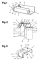
- 1 denotes a luminaire housing which is trapezoidal in cross section, the side walls of which serve as socket holders 1.1 and in each of which a push-through opening 1.11 and a centering hole 1.12 are provided for receiving a commercially available socket 2.
- the socket 2 consists of a socket body 2.1 and a socket foot 2.2, which has spring elements 2.21 and a centering cam 2.22.
- One end of a fluorescent lamp (tubular lamp) 3 with a glass bulb 3.1 is closed with a base 3.2 and connected to the socket body 2.1 via contact pins 3.21.
- a bridge-shaped spacer 4 is formed by a first support leg 4.1, a second support leg 4.2 and a web 4.3, to which a push-through opening 4.31 and a centering hole 4.32 are provided.
- a down on three sides cut from the web 4.3 and on the fourth, firmly connected to the web 4.3 the first spring tongue bent out is designated 4.4
- a second spring tongue cut out on two sides from the second support leg 4.2 is designated 4.5.
- the opening created by bending out the first spring tongue 4.4 simultaneously forms the push-through opening 4.31 for receiving the socket 2.
- the ends of the spring tongues 4.4; 4.5 are in each case in the form of a hook-shaped edge 4.41 directed outwards from the push-through opening 4.31; 4.51 trained.
- a predetermined distance between the holder 1.1 and the glass bulb 3.1 has the reference number 5.
- Push-through sockets with a lampholder body and lampholder base are usually used for holding and spacing tubular lamps.
- the socket 2 is pushed through from the inside through the through-opening 1.11 provided in a lamp housing wall or in a mounting rail, both referred to below as the socket holder 1.1, until the spring elements 2.21 of the socket base 2.2 engage with the socket holder 1.1.
- the centering cam 2.22 engages in the centering hole 1.12 and centers the frame 2.
- the distance 5 of the glass bulb 3.1 from the frame carrier 1.1 is determined by the height of the frame body 2.1 and is usually in the centimeter range.
- the ignition electrode required for starterless ignition consists either of a metal strip along the glass bulb 3.1 or, if the distance 5 is reduced to a few tenths of a millimeter, from the holder 1.1 itself.
- the spacer 4 ensures the required distance 5.
- the structure of the spacer 4 enables fluorescent lamps with different glass bulb diameters to be required even with lights with starterless systems Adjust distance 5.
- the bridge-shaped spacer 4 is placed on the inside of the holder 1.1 on the push-through opening 1.11.
- the distance 5 given by the starterless ignition and depending on Fluorescent lamp type varying glass bulb diameter with the stipulation of the height of the support leg 4.1; 4.2 taken into account.
- the hook-shaped edges 4.41; 4.51 of the spring tongues 4.4; 4.5 through the push-through opening 1.11 through the holder 1.1.
- the socket 2 is no longer pushed through the through opening 1.11, but from the web 4.3 through the through opening 4.31 until the spring elements 2.21 lock.
- the centering hole 4.32 is functional and the dimensions are identical to the centering hole 1.12.
Landscapes
- Engineering & Computer Science (AREA)
- General Engineering & Computer Science (AREA)
- Fastening Of Light Sources Or Lamp Holders (AREA)
- Vessels And Coating Films For Discharge Lamps (AREA)
- Non-Portable Lighting Devices Or Systems Thereof (AREA)
Claims (2)
- Dispositif pour relier de façon amovible et sans vis une douille de lampe fluorescente (2) à un support de douille (1.1), comportant une pièce d'écartement (4) en forme de pont qui possède une branche centrale (4.3), une ou plusieurs premières branches d'appui coudées (4.1) et une ou plusieurs secondes branches d'appui coudées (4.2) destinées à poser la pièce d'écartement (4) sur un creux (1.11) prévu dans le support de douille (1.1) et à fixer la branche centrale (4.3), à l'aide des branches d'appui (4.1 ; 4.2), à une certaine distance du creux (1.11) prévu dans le support de douille (1.1),- ladite pièce d'écartement (4) possédant une ou plusieurs premières languettes élastiques (4.4) qui sont découpées, sur trois côtés, dans la branche centrale (4.3) et, sur le quatrième côté, qui est relié de façon fixe à la branche centrale (4.3), sont pliées vers l'extérieur et vers le bas, en direction du côté de la branche centrale (4.3) où se trouvent les branches d'appui (4.1 ; 4.2),- étant précise que l'orifice obtenu dans la branche centrale (4.3) par le pliage vers l'extérieur de la première languette élastique (4.4) définit en même temps un orifice de passage (4.31) destiné à recevoir la douille de lampe fluorescente (2),- ladite pièce d'écartement (4) possédant une ou plusieurs secondes lanuettes élastiques (4.5) découpées, sur deux côtés, dans la seconde branche d'appui (4.2),- étant précisé que les deux languettes élastiques (4.4 ; 4.5) possèdent chacune, du côté opposé au côté relié de façon fixe à la branche centrale (4.3), respectivement à la seconde branche d'appui (4.2), un bord en forme de crochet (4.41 ; 4.51) dirigé vers l'extérieur et à l'opposé de l'orifice de passage (4.31), destiné à l'ancrage de la pièce d'écartement (4) au niveau du creux (1.11) prévu dans le support de douille (1.1), et- étant précisé que la branche centrale (4.3) possède un ou plusieurs trous de centrale (4.32) prévu pour le centrage de la douille de lampe fluorescente (2).
- Dispositif selon la revendication 1, caractérisé en ce que la pièce d'écartement (4) est réalisée d'une seule pièce.
Priority Applications (1)
| Application Number | Priority Date | Filing Date | Title |
|---|---|---|---|
| AT87116490T ATE78907T1 (de) | 1987-03-20 | 1987-11-09 | Distanzstueck fuer leuchten mit rohrfoermigen lampen. |
Applications Claiming Priority (2)
| Application Number | Priority Date | Filing Date | Title |
|---|---|---|---|
| CH106587 | 1987-03-20 | ||
| CH1065/87 | 1987-03-20 |
Publications (3)
| Publication Number | Publication Date |
|---|---|
| EP0283567A2 EP0283567A2 (fr) | 1988-09-28 |
| EP0283567A3 EP0283567A3 (en) | 1989-09-06 |
| EP0283567B1 true EP0283567B1 (fr) | 1992-07-29 |
Family
ID=4201633
Family Applications (1)
| Application Number | Title | Priority Date | Filing Date |
|---|---|---|---|
| EP87116490A Expired - Lifetime EP0283567B1 (fr) | 1987-03-20 | 1987-11-09 | Pièce d'écartement pour armature à lampe tubulaire |
Country Status (4)
| Country | Link |
|---|---|
| EP (1) | EP0283567B1 (fr) |
| AT (1) | ATE78907T1 (fr) |
| DE (1) | DE3780806D1 (fr) |
| ES (1) | ES2033771T3 (fr) |
Family Cites Families (4)
| Publication number | Priority date | Publication date | Assignee | Title |
|---|---|---|---|---|
| CH347264A (de) * | 1956-01-14 | 1960-06-30 | Busch Jaeger Duerener Metall | Fassung für Röhrenlampen |
| US3176260A (en) * | 1962-06-20 | 1965-03-30 | Miller Co | Socket retainer clip for light fixtures |
| FR1347017A (fr) * | 1962-08-16 | 1963-12-27 | Rapid Sa | Dispositif de fixation |
| NL6912548A (fr) * | 1968-08-27 | 1970-03-03 |
-
1987
- 1987-11-09 EP EP87116490A patent/EP0283567B1/fr not_active Expired - Lifetime
- 1987-11-09 AT AT87116490T patent/ATE78907T1/de not_active IP Right Cessation
- 1987-11-09 DE DE8787116490T patent/DE3780806D1/de not_active Expired - Fee Related
- 1987-11-09 ES ES198787116490T patent/ES2033771T3/es not_active Expired - Lifetime
Also Published As
| Publication number | Publication date |
|---|---|
| DE3780806D1 (de) | 1992-09-03 |
| ES2033771T3 (es) | 1993-04-01 |
| EP0283567A3 (en) | 1989-09-06 |
| EP0283567A2 (fr) | 1988-09-28 |
| ATE78907T1 (de) | 1992-08-15 |
Similar Documents
| Publication | Publication Date | Title |
|---|---|---|
| EP0897511B1 (fr) | Lampe a champ d'eclairage lineaire susceptible de s'inserer dans un montage de bande lumineuse | |
| EP0486714B1 (fr) | Rail pour appareils d'éclairage | |
| DE3714196C2 (de) | Versorgungsbalken für die Intensivpflege | |
| EP0138746A1 (fr) | Armature avec source lumineuse linéaire accessoire | |
| DE202007017735U1 (de) | Lichtbandsystem | |
| EP3114400A1 (fr) | Luminaire ou ensemble lumineux comprenant un élément support allongé et un module lumineux fixé de manière libérable | |
| EP0283567B1 (fr) | Pièce d'écartement pour armature à lampe tubulaire | |
| DE3818517C2 (de) | Lampenfassung | |
| EP4105546A1 (fr) | Luminaire | |
| DE29600594U1 (de) | Einseitig gesockelte Niederdruckentladungslampe und zugehörige Fassung | |
| DE19721340A1 (de) | Leuchte | |
| DE9400976U1 (de) | Vorrichtung zur Bildung von Lichtbändern | |
| DE10234459B4 (de) | Verbindungselement zum Befestigen eines optischen Leuchtenbauteils an einer Leuchte und Leuchte | |
| DE19509112A1 (de) | Kompaktleuchtstofflampe mit kreisrundem Gasentladungsgefäß | |
| EP0593871B1 (fr) | Agencement lumineux à armatures lumineuses disposées l'une derrière l'autre ou cÔte-à-cÔte | |
| DE4106322C2 (de) | Beleuchtungseinrichtung für einen elektrischen Zigarrenanzünder | |
| EP0114621B1 (fr) | Armature lumineuse et procédé de montage | |
| DE3700549C2 (de) | Leuchtstofflampenleuchte | |
| DE2458305C2 (de) | Adapter zur Halterung einer Leuchtdiode auf einer gedruckten Schaltung | |
| EP1132681B1 (fr) | Système de rails de support | |
| DE3904987A1 (de) | Leuchtentraeger fuer mit niederspannung betriebene miniaturlampen | |
| EP1443266B1 (fr) | Dispositif de fixation pour deux supports de lampe | |
| DE10247176A1 (de) | Elektrische Weihnachtsbaumbeleuchtung | |
| DE19808914B4 (de) | Hängeleuchte mit einer Seilsicherung und zugehöriger Seilhalter | |
| DE9304480U1 (de) | Leuchteinheit |
Legal Events
| Date | Code | Title | Description |
|---|---|---|---|
| PUAI | Public reference made under article 153(3) epc to a published international application that has entered the european phase |
Free format text: ORIGINAL CODE: 0009012 |
|
| AK | Designated contracting states |
Kind code of ref document: A2 Designated state(s): AT CH DE ES FR GB IT LI |
|
| PUAL | Search report despatched |
Free format text: ORIGINAL CODE: 0009013 |
|
| AK | Designated contracting states |
Kind code of ref document: A3 Designated state(s): AT CH DE ES FR GB IT LI |
|
| 17P | Request for examination filed |
Effective date: 19900115 |
|
| 17Q | First examination report despatched |
Effective date: 19911022 |
|
| GRAA | (expected) grant |
Free format text: ORIGINAL CODE: 0009210 |
|
| AK | Designated contracting states |
Kind code of ref document: B1 Designated state(s): AT CH DE ES FR GB IT LI |
|
| REF | Corresponds to: |
Ref document number: 78907 Country of ref document: AT Date of ref document: 19920815 Kind code of ref document: T |
|
| REF | Corresponds to: |
Ref document number: 3780806 Country of ref document: DE Date of ref document: 19920903 |
|
| GBT | Gb: translation of ep patent filed (gb section 77(6)(a)/1977) | ||
| ET | Fr: translation filed | ||
| ITF | It: translation for a ep patent filed | ||
| REG | Reference to a national code |
Ref country code: ES Ref legal event code: FG2A Ref document number: 2033771 Country of ref document: ES Kind code of ref document: T3 |
|
| PLBE | No opposition filed within time limit |
Free format text: ORIGINAL CODE: 0009261 |
|
| STAA | Information on the status of an ep patent application or granted ep patent |
Free format text: STATUS: NO OPPOSITION FILED WITHIN TIME LIMIT |
|
| 26N | No opposition filed | ||
| PGFP | Annual fee paid to national office [announced via postgrant information from national office to epo] |
Ref country code: GB Payment date: 19951024 Year of fee payment: 9 |
|
| PGFP | Annual fee paid to national office [announced via postgrant information from national office to epo] |
Ref country code: DE Payment date: 19951026 Year of fee payment: 9 |
|
| PGFP | Annual fee paid to national office [announced via postgrant information from national office to epo] |
Ref country code: FR Payment date: 19951030 Year of fee payment: 9 Ref country code: AT Payment date: 19951030 Year of fee payment: 9 |
|
| PGFP | Annual fee paid to national office [announced via postgrant information from national office to epo] |
Ref country code: ES Payment date: 19951107 Year of fee payment: 9 |
|
| PGFP | Annual fee paid to national office [announced via postgrant information from national office to epo] |
Ref country code: CH Payment date: 19960220 Year of fee payment: 9 |
|
| PG25 | Lapsed in a contracting state [announced via postgrant information from national office to epo] |
Ref country code: GB Effective date: 19961109 Ref country code: AT Effective date: 19961109 |
|
| PG25 | Lapsed in a contracting state [announced via postgrant information from national office to epo] |
Ref country code: ES Free format text: LAPSE BECAUSE OF NON-PAYMENT OF DUE FEES Effective date: 19961110 |
|
| PG25 | Lapsed in a contracting state [announced via postgrant information from national office to epo] |
Ref country code: LI Effective date: 19961130 Ref country code: CH Effective date: 19961130 |
|
| GBPC | Gb: european patent ceased through non-payment of renewal fee |
Effective date: 19961109 |
|
| REG | Reference to a national code |
Ref country code: CH Ref legal event code: PL |
|
| PG25 | Lapsed in a contracting state [announced via postgrant information from national office to epo] |
Ref country code: FR Effective date: 19970731 |
|
| PG25 | Lapsed in a contracting state [announced via postgrant information from national office to epo] |
Ref country code: DE Effective date: 19970801 |
|
| REG | Reference to a national code |
Ref country code: FR Ref legal event code: ST |
|
| REG | Reference to a national code |
Ref country code: ES Ref legal event code: FD2A Effective date: 19971213 |
|
| PG25 | Lapsed in a contracting state [announced via postgrant information from national office to epo] |
Ref country code: IT Free format text: LAPSE BECAUSE OF NON-PAYMENT OF DUE FEES;WARNING: LAPSES OF ITALIAN PATENTS WITH EFFECTIVE DATE BEFORE 2007 MAY HAVE OCCURRED AT ANY TIME BEFORE 2007. THE CORRECT EFFECTIVE DATE MAY BE DIFFERENT FROM THE ONE RECORDED. Effective date: 20051109 |