EP0285177A2 - Servolenkung mit einem elektrischen Motor - Google Patents
Servolenkung mit einem elektrischen Motor Download PDFInfo
- Publication number
- EP0285177A2 EP0285177A2 EP88105311A EP88105311A EP0285177A2 EP 0285177 A2 EP0285177 A2 EP 0285177A2 EP 88105311 A EP88105311 A EP 88105311A EP 88105311 A EP88105311 A EP 88105311A EP 0285177 A2 EP0285177 A2 EP 0285177A2
- Authority
- EP
- European Patent Office
- Prior art keywords
- motor
- relative angular
- input
- target value
- current target
- Prior art date
- Legal status (The legal status is an assumption and is not a legal conclusion. Google has not performed a legal analysis and makes no representation as to the accuracy of the status listed.)
- Ceased
Links
- 238000006073 displacement reaction Methods 0.000 claims abstract description 43
- 238000001514 detection method Methods 0.000 claims description 15
- 238000004519 manufacturing process Methods 0.000 claims description 9
- 238000010276 construction Methods 0.000 description 3
- 238000010586 diagram Methods 0.000 description 3
- 230000003321 amplification Effects 0.000 description 1
- 238000006243 chemical reaction Methods 0.000 description 1
- 230000007423 decrease Effects 0.000 description 1
- 238000009499 grossing Methods 0.000 description 1
- 230000007935 neutral effect Effects 0.000 description 1
- 238000003199 nucleic acid amplification method Methods 0.000 description 1
- 239000002699 waste material Substances 0.000 description 1
Images


Classifications
-
- B—PERFORMING OPERATIONS; TRANSPORTING
- B62—LAND VEHICLES FOR TRAVELLING OTHERWISE THAN ON RAILS
- B62D—MOTOR VEHICLES; TRAILERS
- B62D5/00—Power-assisted or power-driven steering
- B62D5/04—Power-assisted or power-driven steering electrical, e.g. using an electric servo-motor connected to, or forming part of, the steering gear
- B62D5/0457—Power-assisted or power-driven steering electrical, e.g. using an electric servo-motor connected to, or forming part of, the steering gear characterised by control features of the drive means as such
- B62D5/046—Controlling the motor
- B62D5/0463—Controlling the motor calculating assisting torque from the motor based on driver input
Definitions
- the present invention relates to a power steering system having an electric motor incorporated therein, and more particularly to a power steering system comprising an input shaft fixed to a steering wheel, an output shaft coupled to an electric motor via a reduction gear, and a torsion bar provided between the input and output shafts, such that the output shaft is rotatable by the resultant of a torque for the person to rotate the steering wheel and the torque of the motor.
- the torque for the person to rotate the steering wheel will be referred to as an "input torque,” the torque of the motor as an “auxiliary torque,” and the resultant torque as a “steering torque.”
- Such a power steering system which comprises means for detecting the input torque, and control means for controlling the auxiliary torque, i.e. the current through motor, in accordance with the output of the detecting means;(see JP-A1-59-77966).
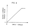
- the conventional system involves a linear relation between the input torque and the motor current target value as shown in Fig. 6 and therefore has the following problem.
- the steering torque involved in stopping a motor vehicle differs greatly from that required during running, and stopping requires a greater torque than running.
- the input torque has a linear relationship with the motor current target value, so that if a suitable magnitude of auxiliary torque is set for stopping, the auxiliary torque during running becomes excessive to make the steering wheel feel too light to handle, whereas when the steering toque is set to a suitable magnitude for running, too small a torque will result to make the wheel feel heavier when the vehicle is to be stopped. Accordingly, it has been proposed to control the steering torque in response to the speed of the vehicle, but this mode of control generally encounters difficulties in a very low speed range because of the limitations imposed on the speed sensor and signal detection circuit.
- An object of the present invention is to provide a power steering system for producing a suitable auxiliary torque when the motor vehicle is to be stopped and also during driving so as to render the steering wheel operable suitably.
- Another object of the invention is to preclude vibration of the steering system.
- the present invention provides a power steering system having an electric motor incorported therein and including an input shaft fixed to a steering wheel, an output shaft coupled to the motor via a reduction gear, and a torsion bar provided between the input and output shafts, the output shaft being rotatable by the resultant of a torque for the person to rotate the steering wheel and the torque of the motor, the system being characterized in that it comprises: a sensor for detecting the relative angular displacement between the input shaft and the output shaft, and a microcomputer having stored therein the relationship between the relative angular displacement and the motor current target value for determining the direction of rotation of the motor and a motor current target value from the output of the sensor to produce outputs, the relationship stored in the microcomputer being a nonlinear relationship wherein variations in the motor current target value with the relative angular displacement are small in the range of small relative angular displacements but are great in the range of great relative angular displacements.
- the microcomputer determines the direction of rotation of the motor and the desired motor current target value from the relative angular displacement detected by the sensor and produces outputs representing the result, thereby causing the motor to produce an auxiliary torque corresponding to the angular displacement between the input and outpust shafts, i.e., the input torque.
- the relationship stored in the microcomputer is nonlinear as stated above, so that when the relative angular displacement is great as when the vehicle is to be stopped, a great auxiliary torque is produced to render the steering wheel easy to handle, whereas when the relative angular displacement is small as during running, the auxiliary torque is reduced not to make the wheel too light.
- the steering wheel can be handled optimally for stopping and also for driving.
- the operating time interval after the microcomputer has detected an input from the sensor until it detects another input following the production of a motor current target value is up to 2 milliseconds, and the operating time interval required for the production of the target value after the detection of the input is up to 500 microseconds.
- vibration occurs in the steering system, whereas such vibration can be obviated when these time intervals are up to 2 milliseconds and up to 500 microseconds, respectively.
- Fig. 1 is a diagram showing a power steering system incorporating an electric motor
- Fig. 2 is an enlarged fragmentary view of the same.
- the power steering system has a steering shaft which is divided generally into an input shaft 10 and an output shaft 11, and a torsion bar 12 is provided therebetween.
- the output shaft 11 comprises three portions which are interconnected by universal joints 13 and 14, i.e., an upper output shaft 11a, an intermediate output shaft 11b and a lower output shaft 11c.
- the input shaft 10 has a steering wheel 15 fixed thereto.
- the lower output shaft 11c is connected to a rack-pinion steering gear assembly 16.
- Via a suitable reduction gear 17, a d.c. servomotor 18 is coupled to a suitable portion of the output shaft 11, for example, to the upper output shaft 11a.
- a d.c. servomotor 18 is coupled to a suitable portion of the output shaft 11, for example, to the upper output shaft 11a.
- a tubular member 19 provided around the torsion bar 12 and extending toward the input shaft 10 has one end secured to the upper end of the upper output shaft 11a.
- a relative angular displacement sensor 20 comprising a potentiometer is provided between a flange 19a of the tubular member 19 and the lower end of the input shaft 10.
- the sensor 20 has output wires 21 extending outward through a split ring 22 and connected to a control unit 23 for controlling the motor 18.
- the sensor 20 detects the input torque, i.e., the relative angular displacement between the input shaft 10 and the output shaft 11.
- the output voltage of the sensor 20 varies linearly width the relative angular dispacement.
- the zero point of the displacement is a neutral point where the input torque is zero.
- the positive displacement stands for the forward direction of rotation, and the negative displacement for the reverse direction.
- Fig. 3 shows the contruction of the control unit 23 for illustrative purposes.
- the motor 18 is connected to a control circuit 24 including four diodes D1, D2, D3, D5 and four switching transistors Q1, Q2, Q3, Q4.
- a resistor 25 for detecting the motor current is connected to the control circuit 24.
- the motor control circuit 24 itself is already known. Only while the first and fourth transistors Q1, Q4 are in conduction, a forward current flows to rotate the motor 18 forward. Only while the second and third transistors Q2, Q3 are in conduction, a reverse current flows, rotating the motor 18 reversely.
- the current value of the motor 18, i.e. the auxiliary torque is controlled by controlling the duration of conduction of the transistors Q1 to Q4.
- the output of the angular displacement sensor 20 is fed to a microcomputer 28 via an amplifier 26 and an AD converter 27.
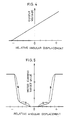
- the microcomputer 28 has stored therein the above-mentioned relationship between the output of the sensor 20 and the relative angular displacement shown in Fig. 4 and the relationship between the relative angular displacement and the motor current target value shown in Fig. 5.
- the relationship shown in Fig. 5 is nonlinear, such that the graph representing variations in the motor current target value at varying relative angular displacements has a small slope in the ragne A of small displacements but a great slope in the range F of great displacements.
- the relative angular displacement is greatest when the vehicle is to be stopped and decreases as the speed increases, so that the range A of small relative angular displacements will be referred to as a high-speed range, and the range B of great relative angular displacements as a low-speed range.
- the output of the sensor 20, as converted by the AD converter 27, is fed to the microcomputer 28, which determines the direction of rotation of the motor 18 and a proper motor current target value based on the relationships of Figs. 4 and 5 and produces outputs representing the result.
- the microcomputer 28 performs this operation, i.e. detection of the input from the sensor 20 through the production of the target value, within 500 microseconds, and repeatedly conducts the operation at a predetermined time interval of up to 2 milliseocnds. Stated more specifically, the microcomputer 28 first determines the direction and value of the relative angular displacement from the AD-converted output of the sensor 20 with reference to the relationship of Fig.
- a rotational direction signal S1 or S2 indicating the direction of the angular displacement.
- the positive rotational direction signal S1 is given when the relative angular displacement is positive, or the negative rotational direction signal S2 is given when the displacement is negative.
- the microcomputer further determines the proper motor current target value from the value of angular displacement thus obtained, with reference to the relationship of Fig. 5 and feeds the resulting output to a DA converter 30.
- the output of the DA converter 30 is fed to an error amplifier 32 along with a feedback signal obtained from the voltage (proportional to the motor current) across the resistor 25 of the motor control circuit 24 by smoothing with a low-pass filter 31 and amplification.
- the output of the error amplifier 32 is given to a pulse-width modulation (PWM) circuit 33, which produces an output with a pulse width varying with the output of the amplifier 32.
- PWM pulse-width modulation
- the logic control circuit 29 controls the rotational direction of the motor 18 and the motor current in the following manner in accordance with the rotational direction signal S1 or S2 from the microcomputer 28 and with the output of the PWM circuit 33.
- the circuit 29 holds the first and fourth transistors Q1, Q4 in conduction to rotate the motor 18 forward.
- the second and third transistors Q2, Q3 are held in conduction to rotate the mortor 18 in the reverse direction. In either case, the motor current is made equal to the target value produced from the microcomputer 28.
- the PWM circuit 33 and the logic control circuit 29 per se are each of known construction.
- the steering wheel can be handled suitably for stopping or for driving.
- the motor current target value is great (low-speed range B in Fig. 5) as when the steering wheel is handled at rest, the motor current target value is great. to produce a great auxiliary torque, making the wheel feel light for smooth steering at rest.
- the motor current target value is small to give a small auxiliary torque so as not to render the steering wheel too light to handle.
- the operating time involving AD conversion and calculation and required for producing an output after the detection of an input is waste time from the viewpoint of control. If this period of time and also the operating time interval from the detection of the AD-converted input until the detection of the subsequent input following production of the outputs are long, a phase lag occurs between the AD-converted input signal and the computer output signal to result in a phase lag between the input torque and the auxiliary torque, giving rise of the vibration of the steering system.
- the present embodiment obviates the vibration because the operating time interval required for the production of the output after the detection of the relative angular displacement is up to 500 microseconds and further because the operating time interval from the detection of the input until the detection of the subsequent input following the production of the output is as short as up to 2 milliseconds.
Landscapes
- Engineering & Computer Science (AREA)
- Chemical & Material Sciences (AREA)
- Combustion & Propulsion (AREA)
- Transportation (AREA)
- Mechanical Engineering (AREA)
- Power Steering Mechanism (AREA)
- Steering Control In Accordance With Driving Conditions (AREA)
Applications Claiming Priority (2)
| Application Number | Priority Date | Filing Date | Title |
|---|---|---|---|
| JP83536/87 | 1987-04-03 | ||
| JP8353687 | 1987-04-03 |
Publications (2)
| Publication Number | Publication Date |
|---|---|
| EP0285177A2 true EP0285177A2 (de) | 1988-10-05 |
| EP0285177A3 EP0285177A3 (de) | 1989-07-19 |
Family
ID=13805224
Family Applications (1)
| Application Number | Title | Priority Date | Filing Date |
|---|---|---|---|
| EP88105311A Ceased EP0285177A3 (de) | 1987-04-03 | 1988-03-31 | Servolenkung mit einem elektrischen Motor |
Country Status (3)
| Country | Link |
|---|---|
| US (1) | US4871039A (de) |
| EP (1) | EP0285177A3 (de) |
| CA (1) | CA1275259C (de) |
Cited By (1)
| Publication number | Priority date | Publication date | Assignee | Title |
|---|---|---|---|---|
| EP0351087A3 (en) * | 1988-07-14 | 1990-02-28 | Mitsubishi Denki Kabushiki Kaisha | Unitized electric power steering apparatus |
Families Citing this family (14)
| Publication number | Priority date | Publication date | Assignee | Title |
|---|---|---|---|---|
| JPH06293265A (ja) * | 1993-04-07 | 1994-10-21 | Rhythm Corp | 電動パワーステアリング装置 |
| GB9316841D0 (en) * | 1993-08-13 | 1993-09-29 | Lucas Ind Plc | Optical torque sensor incorporating sensor failure diagnostics |
| KR100204643B1 (ko) * | 1993-09-20 | 1999-06-15 | 홍순영 | 전자식 동력조향장치 |
| JP3525195B2 (ja) * | 1994-08-02 | 2004-05-10 | 光洋精工株式会社 | 電動パワーステアリング装置 |
| US5661466A (en) * | 1995-02-07 | 1997-08-26 | Robertshaw Controls Company | Angular displacement signalling device |
| US6293366B1 (en) | 2000-02-16 | 2001-09-25 | Ford Global Technologies, Inc. | Vehicle electric power assist steering system and method using angle based torque estimation |
| US6425454B1 (en) | 2000-02-16 | 2002-07-30 | Ford Global Technologies, Inc. | Vehicle electric power assist steering system and method using velocity based torque estimation |
| US6250419B1 (en) | 2000-02-16 | 2001-06-26 | Ford Global Technologies, Inc. | Vehicle electric power assist steering system and method using H-infinity control |
| US6619444B2 (en) * | 2001-04-04 | 2003-09-16 | Delphi Technologies, Inc. | Magnetorheological fluid stopper at electric motor |
| US6651771B2 (en) * | 2001-10-20 | 2003-11-25 | Ford Global Technologies, Llc | H-infinity control and gain scheduling method for electric power assist steering system |
| US6978858B1 (en) * | 2004-06-14 | 2005-12-27 | Bischoff David R | Visual reference control apparatus for hydraulic actuator systems |
| RU2412839C2 (ru) * | 2006-10-19 | 2011-02-27 | Тойота Дзидося Кабусики Кайся | Устройство управления гашением колебаний транспортного средства |
| GB2481877A (en) * | 2008-10-31 | 2012-01-11 | Toyota Motor Co Ltd | Driving force controller and controlling method of driving force controller |
| JP5262811B2 (ja) * | 2008-10-31 | 2013-08-14 | トヨタ自動車株式会社 | 車両のバネ上制振制御装置 |
Family Cites Families (13)
| Publication number | Priority date | Publication date | Assignee | Title |
|---|---|---|---|---|
| US4471280A (en) * | 1983-05-06 | 1984-09-11 | The Bendix Corporation | Anti-log power amplifier for reversible D.C. motor in automotive steering controls |
| JPS60193765A (ja) * | 1984-03-16 | 1985-10-02 | Hitachi Ltd | パワ−ステアリング制御装置 |
| JPS6189170A (ja) * | 1984-10-08 | 1986-05-07 | Fuji Heavy Ind Ltd | 電動式パワ−ステアリング装置 |
| JPS6198675A (ja) * | 1984-10-19 | 1986-05-16 | Fuji Heavy Ind Ltd | 電動式パワ−ステアリング装置のモ−タ制御装置 |
| JPS61105272A (ja) * | 1984-10-26 | 1986-05-23 | Honda Motor Co Ltd | 電磁型倍力装置 |
| JPS61122078A (ja) * | 1984-11-20 | 1986-06-10 | Fuji Heavy Ind Ltd | 電動式パワステアリング装置の制御装置 |
| JPS61125964A (ja) * | 1984-11-21 | 1986-06-13 | Toyoda Mach Works Ltd | 電気式動力舵取装置 |
| JP2568817B2 (ja) * | 1984-11-29 | 1997-01-08 | 富士重工業株式会社 | 電動式パワ−ステアリング装置のモ−タ制御装置 |
| US4676331A (en) * | 1984-12-20 | 1987-06-30 | Kabushiki Kaisha Toyoda Jidoshokki Seisakusho | Torque detecting apparatus for electrical power steering system |
| JPS61155056A (ja) * | 1984-12-27 | 1986-07-14 | Toyoda Mach Works Ltd | 電気式動力舵取装置 |
| KR920007039B1 (ko) * | 1985-02-02 | 1992-08-24 | 가부시기가이샤 히다찌세이사꾸쇼 | 전동 파워스티어링장치 |
| JPH0662093B2 (ja) * | 1985-03-29 | 1994-08-17 | 豊田工機株式会社 | 電気式動力舵取装置 |
| JPS62292574A (ja) * | 1986-06-12 | 1987-12-19 | Mitsubishi Electric Corp | モ−タ駆動式パワ−ステアリング装置のフエ−ルセ−フ方法 |
-
1988
- 1988-03-29 US US07/174,911 patent/US4871039A/en not_active Expired - Lifetime
- 1988-03-30 CA CA000562868A patent/CA1275259C/en not_active Expired - Lifetime
- 1988-03-31 EP EP88105311A patent/EP0285177A3/de not_active Ceased
Cited By (2)
| Publication number | Priority date | Publication date | Assignee | Title |
|---|---|---|---|---|
| EP0351087A3 (en) * | 1988-07-14 | 1990-02-28 | Mitsubishi Denki Kabushiki Kaisha | Unitized electric power steering apparatus |
| US4986381A (en) * | 1988-07-14 | 1991-01-22 | Mitsubishi Denki Kabushiki Kaisha | Unitized electric power steering apparatus |
Also Published As
| Publication number | Publication date |
|---|---|
| US4871039A (en) | 1989-10-03 |
| EP0285177A3 (de) | 1989-07-19 |
| CA1275259C (en) | 1990-10-16 |
Similar Documents
| Publication | Publication Date | Title |
|---|---|---|
| EP0285177A2 (de) | Servolenkung mit einem elektrischen Motor | |
| US6470994B1 (en) | Electric power steering apparatus | |
| EP1362765B1 (de) | Kraftfahrzeuglenkung | |
| JPH0288362A (ja) | パワーステアリング装置 | |
| US4778021A (en) | Motor-driven power steering system for a vehicle | |
| EP1093992A3 (de) | Elektrische Servolenkung für ein Fahrzeug | |
| EP0343693A2 (de) | Von einem Motor angetriebene Servolenkung für ein Fahrzeug | |
| JP2010052640A (ja) | 電気式動力舵取装置 | |
| JPS61226363A (ja) | 電気式動力舵取装置 | |
| JPS63162370A (ja) | モ−タ駆動式パワ−ステアリング制御装置 | |
| US4849889A (en) | Motor-driven power steering system for a vehicle | |
| JP6326171B1 (ja) | 操舵制御装置、電動パワーステアリング装置 | |
| US4724916A (en) | Motor-driven power steering system for a vehicle | |
| JPH0687458A (ja) | 電動式パワーステアリング装置 | |
| JP2596049B2 (ja) | 電動パワーステアリング装置 | |
| JPH0651475B2 (ja) | 電動式パワーステアリング装置 | |
| JPH0229017Y2 (de) | ||
| JPH05338544A (ja) | モータ制御装置 | |
| JPH021712B2 (de) | ||
| CN110550098A (zh) | 用于正三轮车辆的辅助转向装置及正三轮车辆 | |
| JPS6311480A (ja) | 電動パワ−ステアリングの制御装置 | |
| JP4639522B2 (ja) | 電動パワーステアリングのアシストモータ制御装置 | |
| JP2532115B2 (ja) | 電動パワ―ステアリング装置 | |
| JPH01257676A (ja) | 電動式パワーステアリング装置 | |
| JPH0657531B2 (ja) | 電動モ−タ式パワ−ステアリング |
Legal Events
| Date | Code | Title | Description |
|---|---|---|---|
| PUAI | Public reference made under article 153(3) epc to a published international application that has entered the european phase |
Free format text: ORIGINAL CODE: 0009012 |
|
| AK | Designated contracting states |
Kind code of ref document: A2 Designated state(s): DE FR GB |
|
| PUAL | Search report despatched |
Free format text: ORIGINAL CODE: 0009013 |
|
| AK | Designated contracting states |
Kind code of ref document: A3 Designated state(s): DE FR GB |
|
| 17P | Request for examination filed |
Effective date: 19890912 |
|
| 17Q | First examination report despatched |
Effective date: 19891228 |
|
| STAA | Information on the status of an ep patent application or granted ep patent |
Free format text: STATUS: THE APPLICATION HAS BEEN REFUSED |
|
| 18R | Application refused |
Effective date: 19921015 |