EP0285809A2 - Dispositif pour éviter des survitesses pour un moteur à combustion interne - Google Patents
Dispositif pour éviter des survitesses pour un moteur à combustion interne Download PDFInfo
- Publication number
- EP0285809A2 EP0285809A2 EP88103285A EP88103285A EP0285809A2 EP 0285809 A2 EP0285809 A2 EP 0285809A2 EP 88103285 A EP88103285 A EP 88103285A EP 88103285 A EP88103285 A EP 88103285A EP 0285809 A2 EP0285809 A2 EP 0285809A2
- Authority
- EP
- European Patent Office
- Prior art keywords
- pressure chamber
- actuator
- engine
- overrunning
- throttle valve
- Prior art date
- Legal status (The legal status is an assumption and is not a legal conclusion. Google has not performed a legal analysis and makes no representation as to the accuracy of the status listed.)
- Withdrawn
Links
- 238000002485 combustion reaction Methods 0.000 title claims abstract description 15
- 210000000188 diaphragm Anatomy 0.000 claims 4
- 239000000203 mixture Substances 0.000 description 10
- 239000000446 fuel Substances 0.000 description 9
- 230000007423 decrease Effects 0.000 description 3
- 238000001816 cooling Methods 0.000 description 2
- 239000003517 fume Substances 0.000 description 2
- 238000004904 shortening Methods 0.000 description 2
- 230000003245 working effect Effects 0.000 description 2
- 239000000567 combustion gas Substances 0.000 description 1
- 230000003247 decreasing effect Effects 0.000 description 1
- 230000000694 effects Effects 0.000 description 1
- 239000002360 explosive Substances 0.000 description 1
- 239000004744 fabric Substances 0.000 description 1
- 238000009472 formulation Methods 0.000 description 1
- 230000002401 inhibitory effect Effects 0.000 description 1
- 239000002184 metal Substances 0.000 description 1
- 239000011347 resin Substances 0.000 description 1
- 229920005989 resin Polymers 0.000 description 1
Images


Classifications
-
- F—MECHANICAL ENGINEERING; LIGHTING; HEATING; WEAPONS; BLASTING
- F02—COMBUSTION ENGINES; HOT-GAS OR COMBUSTION-PRODUCT ENGINE PLANTS
- F02D—CONTROLLING COMBUSTION ENGINES
- F02D17/00—Controlling engines by cutting out individual cylinders; Rendering engines inoperative or idling
- F02D17/04—Controlling engines by cutting out individual cylinders; Rendering engines inoperative or idling rendering engines inoperative or idling, e.g. caused by abnormal conditions
Definitions
- the present invention relates to a device for inhibiting overrunning of the internal combustion engine in use of its vibrations.
- Portable working machines generally use a two-stroke engine as a power source.
- a diaphragm type carbureter is employed to thereby make it possible to operate a machine in all attitudes.
- the two-stroke engine is used for a chain saw, a brush cutter, etc. It is generally that such a portable working machine is operated with the light-weight, small-size and high-output internal combustion engine fully loaded in order to enhance the working properties.
- the engine brings forth a so-called overrunning by which an allowable number of revolutions exceeds before cutting work takes place to sometimes damage the engine. The overrunning operation likewise occurs also after the cutting work has been completed.
- the overrunning may be avoided if the throttle valve is restored every time of interruption of the work so as not to affect the no-load running when the throttle valve is totally opened.
- the intermittent work is repeatedly carried out, the operator often fails to do so, thus resulting in damages of and shortening of life of the engine.
- the present inventor has proposed an anti-overrunning disclosed in Japanese Patent Application Laid-Open No. 1835/1986.
- a vibrating pump is normally driven to directly supply pressure air to an actuator, and therefore, a diaphragm of the vibrating pump is always unsteady due to the vibrations of the engine; the operating stability is poor; and it is difficult to set an actuating point at which a throttle valve is closed by an actuator during overrunning of the engine.
- the vibrating pump is provided with a spring to force back the diaphragm, and therefore the amplitude of the diaphragm is restricted.
- a vibrating pump has to be increased in size in order to obtain a sufficient pump capacity.
- the present invention provides an arrangement which comprises a vibrating pump for generating pneumatic pressure by vi brations of the engine; an actuator having a rod for urging a throttle valve lever in a direction of closing a throttle valve by virtue of the pneumatic pressure of said vibrating pump; and a vibration sensor positioned in a passage for communicating a pressure chamber of said actuator to atmosphere to open said passage by virtue of the vibrations of the engine during overrunning thereof.
- the present invention comprises a vibrating pump for generating pneumatic pressure by vibrations of the engine; an actuator having a rod for urging a throttle valve lever in a direction of closing a throttle valve by virtue of the pneumatic pressure of said vibrating pump; and a vibration sensor positioned in a passage for communicating a pressure chamber of said actuator to atmosphere to open said passage by virtue of the vibrations of the engine during overrunning thereof, and only the weight is mounted to the diaphragm of the vibrating pump and a return spring is not present, and therefore a device which is small but has a sufficient pump capacity may be obtained.
- the opening degree of the throttle valve of the carbureter is automatically reduced to reduce the flow rate of the mixture taken into engine. Therefore, there is provided a new anti-overrunning device which is positive in operation, may be run at a substantially reasonable fuel cost (rate of fuel consumption) in all running levels of the engine, is free of spark plug from a fog, is less in exhaust fume, and is less tar stayed on the muffler.
- the working properties may be enhanced, and the damage of and the shortening of life of the engine may be avoided.
- a cylinder 16 having cooling fins 15 is closed at its upper end by a cylinder head 13 having cooling fins 12, and a crank case 21 is connected to the lower end thereof.
- a piston 14 fitted in the cylinder 16 and a crank shaft 19 supported on the crank case 21 are connected by a connecting rod 20.
- the piston 14 is moved downward by the explosive force, and simultaneously the combustion gas is exhausted outside via the muffler 11 from an exhaust port 18.
- a carbureter 24 is connected to the intake port 17 through a heat insulating pipe 22.
- An air cleaner, not shown, is connected to an end wall 26 of a body 35 of the carbureter 24.
- a throttle valve 27 is supported by the valve shaft 28 on a venturi 34 formed on the body 35, and fuel is supplied to the venturi 34 by negative pressure of air passing through the venturi 34.
- fuel supplying mechanism is known, for example, in US Patent 3738623 and directly has nothing to do with the gist of the present ivnention, and will not be further described.
- valve shaft 28 An upper end of the valve shaft 28 is rotatably supported on the body 35 by means of a bearing sleeve 38, and an -L shaped throttle valve lever 29 is secured to the upper end.
- One end of a spring 36 wound around the valve shaft 28 is placed in engagement with the throttle valve lever 29 and the other end thereof placed in engagement with the bearing sleeve 38.
- a boss portion of the lever 25 is slipped over the bearing sleeve 38, and one end of a spring 32 wound around the boss portion is placed in engagement with the lever 25 whereas the other end is placed in engagement with a pin 31 of the body 35.
- An engaging portion 37 of the throttle valve lever 29 is projected downwardly so that it may engage with the edge of the lever 25.
- the throttle valve lever 29 is pivotally urged counterclockwise by the force of the spring 36 to cause the engaging portion 37 to abut against the lever 25.
- the lever 25 is pivotally urged clockwise by the strong force of the spring 32 to close the throttle valve 27.
- the throttle valve lever 29 also follows the lever 25 to increase an opening degree of the throttle valve 27.
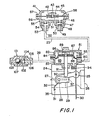
- the anti-overrunning device for the internal combustion engine is composed of a vibrating pump 41, an actuator 81 for reducing an opening degree of the throttle valve 27 by the throttle valve lever 29 and a vibration sensor 101.
- the vibrating pump 41 has a diaphragm 58 sandwiched between cup-like housings 57 and 55 to form an atmospheric chamber 45 and a pressure chamber 46.
- Pad plates 42 and 51 are placed on both surfaces of a diaphragm 58, and a weight 44 is connected by means of a rivet 43.
- the pressure chamber 46 is provided with passages 56 and 47, to which port members 53 and 50, respectively, are connected.
- the port member 53 is provided with a check valve 54 to allow a flow of air from the passage 56 to a passage 52.
- the port member 50 is provided with a check valve 48 to allow flow of air from an atmospheric opening 49 to the passage 47 through a strainer 60 (refer to Fig. 4).
- the passage 52 is connected to an inlet 90 of the actuator 81 by a pipe 23.
- the actuator 81 has a diaphragm 84 sandwiched between cup-like housings 82 and 83 to form a pressure chamber 85 and an atmospheric chamber 86.
- Pad plates 87 and 88 are placed on both surfaces of the diaphragm 84, the plates being connected by the base end of a rod 92.
- the rod 92 slidably inserted into a hole 91 of the housing 83 is projected outward by means of a spring 89 interposed between the pad plate 87 and the housing 82.
- the fore end of the rod 92 is placed into abutment with the aforementioned throttle valve lever 29.
- the pressure chamber 85 and the atmospheric chamber 86 are provided with orifices 93 and 94 in communication with atmosphere respectively, whereby the extreme operation of the actuator 81 may be restricted.
- the vibration sensor 101 is so designed that a closure 105 having a passage 106 is connected to the end of a cup-like housing 102, and a ball 107 is urged against the end of a passage 103 by means of a spring 104 accommodated in the housing 102.
- the above-described vibrating pump 41 is preferably integrally connected to the lower end wall of the body 35 of the carbureter 24, and the actuator 81 and the vibration sensor 101 are connected to the upper end wall of the body 35, as shown in Fig. 3.
- the vibrating pump 41 and the actuator 81 are connected by the pipe 23. However, the vibrating pump 41 and the vibration sensor 101 may be mounted suitably on the engine 10.
- Fig. 4 is an enlarged view showing an embodiment wherein a vibrating pump, a vibration sensor and an actuator are mounted on the body of a carbureter.
- the diaphragm 58 of the vibrating pump 41 can be formed from a ground-fabric contained rubber plate, a thin resin plate and a thin metal plate other than a rubber plate.
- the shape of the diaphragm can be of a convolution type and a bellow-phragm type other than the flat plate.
- the weight 44 may be mounted interiorly of the pressure chamber 46 or mounted interiorly of both atmospheric chamber 45 and pressure chamber 46.
- the actuating point of the vibration sensor 101 may be suitably set by varying the diameter and weight of the ball 107, the set load of the spring 104, the inside diameter of the seat portion of the passage 103 and the like.
- a configuration may be made so that ball 107 is urged against the passage 106 by means of a spring.
- the vibration sensor 101 Since in the state where the engine is less than a predetermined number of revolutions, the intensity of the vibrations of the engine is weak, the vibration sensor 101 is in its closed state, that is, the passage 39 is closed by the ball 107.
- the vibrating pump 41 Upon receipt of the vibration of the engine, the vibrating pump 41 vibrates up and down by the weight 44 supported on the diaphragm 58.
- the diaphragm 58 When the diaphragm 58 is inflated upwardly, pressure of the pressure chamber 46 lowers, and therefore the check valve 48 opens to take air into the pressure chamber 46 from the atmosphere opening 49 having strainer 60.
- the opening degree of the throttle valve 27 is determined by the operating degree of the lever 25 operated by the trigger wire 30.
- the opening degree of the throttle valve 27 is determined depending on the rotated position of the lever 25 operated by the trigger wire 30.
- the vibration sensor 101 again opens, and the opening degree of the throttle valve 27 is decreased by the spring 89 of the actuator 81.
- the operation as described above is repeated whereby the engine is maintained less than a predetermined number of revolutions, and the overrunning of the engine is automatically prevented without the operator's operation of the trigger wire 30 according to the variation of load.
- an actuator 181 connected to the upper end wall of the body 35 of the carbureter 24 is actuated by negative pressure supplied from a vibrating pump 141.
- Members corresponding to those shown in Fig. 4 are indicated by reference numerals to which 100 are added.
- a check valve 154 Provided in an atmospheric opening 149 of the vibrating pump 141 is a check valve 154 to allow a flow of air from a pressure chamber 146 to outside.
- a check valve 148 provided on a passage 152 is a check valve 148 to allow a flow of air from the actuator 181 to the pressure chamber 146.
- the vibration sensor 201 is designed so that a ball 207 is urged against the end of a passage 139 by means of a spring 204 accommodated in a housing integral with the actuator 181.
- the actuator 181 has a diaphragm 184 sandwiched between housings 182 and 183 to form a pressure chamber 185 and an atmospheric chamber 186, the atmospheric chamber 186 and pressure chamber 185 being communicated with atmosphere by orifices 194 and 193, respectively.
- a rod 192 connected to the diaphragm 184 is urged upward by negative pressure supplied from the vibrating pump 141 to the pres sure chamber 185 against the force of a spring 189.
Landscapes
- Engineering & Computer Science (AREA)
- Chemical & Material Sciences (AREA)
- Combustion & Propulsion (AREA)
- Mechanical Engineering (AREA)
- General Engineering & Computer Science (AREA)
- Control Of Throttle Valves Provided In The Intake System Or In The Exhaust System (AREA)
- High-Pressure Fuel Injection Pump Control (AREA)
Applications Claiming Priority (2)
| Application Number | Priority Date | Filing Date | Title |
|---|---|---|---|
| JP88451/87 | 1987-04-10 | ||
| JP62088451A JPS63255532A (ja) | 1987-04-10 | 1987-04-10 | 内燃機関の過回転防止装置 |
Publications (2)
| Publication Number | Publication Date |
|---|---|
| EP0285809A2 true EP0285809A2 (fr) | 1988-10-12 |
| EP0285809A3 EP0285809A3 (fr) | 1989-09-06 |
Family
ID=13943162
Family Applications (1)
| Application Number | Title | Priority Date | Filing Date |
|---|---|---|---|
| EP88103285A Withdrawn EP0285809A3 (fr) | 1987-04-10 | 1988-03-03 | Dispositif pour éviter des survitesses pour un moteur à combustion interne |
Country Status (3)
| Country | Link |
|---|---|
| US (1) | US4796582A (fr) |
| EP (1) | EP0285809A3 (fr) |
| JP (1) | JPS63255532A (fr) |
Families Citing this family (1)
| Publication number | Priority date | Publication date | Assignee | Title |
|---|---|---|---|---|
| US6743211B1 (en) * | 1999-11-23 | 2004-06-01 | Georgia Tech Research Corporation | Devices and methods for enhanced microneedle penetration of biological barriers |
Family Cites Families (6)
| Publication number | Priority date | Publication date | Assignee | Title |
|---|---|---|---|---|
| JPS5946344A (ja) * | 1982-03-03 | 1984-03-15 | Walbro Far East | 2サイクルエンジン過回転防止装置 |
| JPS58172439A (ja) * | 1982-04-01 | 1983-10-11 | Walbro Far East | 電磁変換式エンヂン過回転防止装置 |
| DE3406119A1 (de) * | 1984-02-21 | 1985-08-22 | Fa. Andreas Stihl, 7050 Waiblingen | Zweitaktmotor |
| JPS60228736A (ja) * | 1984-04-25 | 1985-11-14 | Mitsubishi Heavy Ind Ltd | 気化器 |
| JPS60261940A (ja) * | 1984-06-08 | 1985-12-25 | Walbro Far East | 2サイクル内燃機関の過回転防止装置 |
| JPS611835A (ja) * | 1984-06-13 | 1986-01-07 | Walbro Far East | 2サイクル内燃機関の過回転防止装置 |
-
1987
- 1987-04-10 JP JP62088451A patent/JPS63255532A/ja active Granted
- 1987-09-29 US US07/102,133 patent/US4796582A/en not_active Expired - Fee Related
-
1988
- 1988-03-03 EP EP88103285A patent/EP0285809A3/fr not_active Withdrawn
Also Published As
| Publication number | Publication date |
|---|---|
| JPS63255532A (ja) | 1988-10-21 |
| JPH0552408B2 (fr) | 1993-08-05 |
| EP0285809A3 (fr) | 1989-09-06 |
| US4796582A (en) | 1989-01-10 |
Similar Documents
| Publication | Publication Date | Title |
|---|---|---|
| US9534528B2 (en) | Internal combustion engine with fuel system | |
| US6374782B2 (en) | Air-fuel mixture generating device | |
| US20020148419A1 (en) | Fuel injection device and air-fuel mixture generating device provided with fuel injection device | |
| EP0285808B1 (fr) | Dispositif pour éviter des survitesses pour moteur à combustion interne | |
| EP0285809A2 (fr) | Dispositif pour éviter des survitesses pour un moteur à combustion interne | |
| EP0289723A2 (fr) | Dispositif pour éviter des survitesses pour un moteur à combustion interne | |
| EP0289722A2 (fr) | Dispositif pour éviter des survitesses pour un moteur à combustion interne | |
| EP0286818A2 (fr) | Dispositif pour éviter des survitesses pour un moteur à combustion interne | |
| EP0262491A2 (fr) | Starter pour carburateur | |
| JP2785904B2 (ja) | ディーゼルエンジンの停止装置 | |
| JP2835928B2 (ja) | 小型エンジンにおける始動円滑化装置 | |
| JPH045811B2 (fr) | ||
| JPH0310027B2 (fr) | ||
| JP2012177336A (ja) | エンジンおよびそれを備えたエンジン作業機 | |
| JPH0627821Y2 (ja) | 内燃機関装置 | |
| JPS6316835Y2 (fr) | ||
| WO2021065660A1 (fr) | Moteur à combustion interne à deux temps à balayage stratifié de type à guidage d'air, et engin de chantier à moteur | |
| JPS5920868B2 (ja) | エンジン | |
| JPH07224745A (ja) | 手持ち作業機器の手動始動式内燃エンジンの減圧弁 | |
| JPH0226059B2 (fr) | ||
| GB2339843A (en) | Quieter two-stroke i.c. engine with second cylinder to expand exhaust from main cylinder | |
| JPS6235047A (ja) | 内燃機関の始動燃料供給装置 | |
| JP2015172330A (ja) | エンジンの燃料供給装置 | |
| JPS60182349A (ja) | 2サイクル機関の燃料供給装置 | |
| JPH06146907A (ja) | 予圧縮式2サイクルエンジンの吸気装置 |
Legal Events
| Date | Code | Title | Description |
|---|---|---|---|
| PUAI | Public reference made under article 153(3) epc to a published international application that has entered the european phase |
Free format text: ORIGINAL CODE: 0009012 |
|
| AK | Designated contracting states |
Kind code of ref document: A2 Designated state(s): BE DE FR GB IT SE |
|
| PUAL | Search report despatched |
Free format text: ORIGINAL CODE: 0009013 |
|
| AK | Designated contracting states |
Kind code of ref document: A3 Designated state(s): BE DE FR GB IT SE |
|
| 17P | Request for examination filed |
Effective date: 19900306 |
|
| 17Q | First examination report despatched |
Effective date: 19900628 |
|
| STAA | Information on the status of an ep patent application or granted ep patent |
Free format text: STATUS: THE APPLICATION IS DEEMED TO BE WITHDRAWN |
|
| 18D | Application deemed to be withdrawn |
Effective date: 19901113 |