EP0297145A1 - Verfahren und system zum sammeln von müll - Google Patents
Verfahren und system zum sammeln von müll Download PDFInfo
- Publication number
- EP0297145A1 EP0297145A1 EP88900134A EP88900134A EP0297145A1 EP 0297145 A1 EP0297145 A1 EP 0297145A1 EP 88900134 A EP88900134 A EP 88900134A EP 88900134 A EP88900134 A EP 88900134A EP 0297145 A1 EP0297145 A1 EP 0297145A1
- Authority
- EP
- European Patent Office
- Prior art keywords
- waste
- transport tube
- waste container
- vertical
- horizontal transport
- Prior art date
- Legal status (The legal status is an assumption and is not a legal conclusion. Google has not performed a legal analysis and makes no representation as to the accuracy of the status listed.)
- Withdrawn
Links
Images



Classifications
-
- E—FIXED CONSTRUCTIONS
- E04—BUILDING
- E04F—FINISHING WORK ON BUILDINGS, e.g. STAIRS, FLOORS
- E04F17/00—Vertical ducts; Channels, e.g. for drainage
- E04F17/10—Arrangements in buildings for the disposal of refuse
-
- B—PERFORMING OPERATIONS; TRANSPORTING
- B65—CONVEYING; PACKING; STORING; HANDLING THIN OR FILAMENTARY MATERIAL
- B65F—GATHERING OR REMOVAL OF DOMESTIC OR LIKE REFUSE
- B65F5/00—Gathering or removal of refuse otherwise than by receptacles or vehicles
- B65F5/005—Gathering or removal of refuse otherwise than by receptacles or vehicles by pneumatic means, e.g. by suction
-
- Y—GENERAL TAGGING OF NEW TECHNOLOGICAL DEVELOPMENTS; GENERAL TAGGING OF CROSS-SECTIONAL TECHNOLOGIES SPANNING OVER SEVERAL SECTIONS OF THE IPC; TECHNICAL SUBJECTS COVERED BY FORMER USPC CROSS-REFERENCE ART COLLECTIONS [XRACs] AND DIGESTS
- Y10—TECHNICAL SUBJECTS COVERED BY FORMER USPC
- Y10S—TECHNICAL SUBJECTS COVERED BY FORMER USPC CROSS-REFERENCE ART COLLECTIONS [XRACs] AND DIGESTS
- Y10S209/00—Classifying, separating, and assorting solids
- Y10S209/93—Municipal solid waste sorting
Definitions
- the present invention relates to a waste collection system for collecting wastes generated in a building at a predetermined position. More specifically, this invention is concerned with a waste collection system for automatically moving the wastes which are generated in a building such as a condominium building, a hospital, or an office building and are thrown into input ports situated at various places in the building, through a predetermined conveyance path, and accumulating them at a predetermined collection point.
- a waste collection system for automatically moving the wastes which are generated in a building such as a condominium building, a hospital, or an office building and are thrown into input ports situated at various places in the building, through a predetermined conveyance path, and accumulating them at a predetermined collection point.
- the wastes generated in a building such as a condominium have been kept in plastic bags or baskets by the residents of the building, and on the waste collecting day, the wastes were manhandled to the waste accumulation area downstairs.
- an apparatus called a dust chute may have been provided.
- the dust chute is provided to vertically penetrate the building, having holes in the longitudinal direction thereof, namely having an input port at every floor.
- the dust chute is employed, as described above, the waste, which has been stored in the plastic bag, a basket or the like by each resident, is into the dust chute contained in the bag or picked up from a container. The waste falls downstairs and is accumulated thereat.
- the present invention was developed in view of the above-mentioned problems related to the conventional methods of collecting the wastes, and its object is to provide a waste collection system and method therefor which enable the residents to dispose of wastes at various places in the building at any time, reduce the labor required to carry or collect the wastes, and provide for hygiene.
- the" waste collection system of this invention includes:
- Input ports provided at various places in the building: the wastes being thrown through the said input ports;
- the waste container thrown into the said input port falls inside the vertical transport tube.
- the section of the vertical tube hollow is just larger than that of the waste container, so that the air beneath the waste container is compressed as the waste container falls.
- the compressed air functions as a buffer space, reducing the speed at which the said waste container falls. Therefore, the said waste container will not break, and will fall without producing a large noise.
- the waste container is force-fed to the waste accumulation area by supplying air into the horizontal transport tube or by discharging the air therefrom (in this specification and claims, the term "force-feed” means to convey the substance in the tube by supplying air into the tube or sucking it out and discharging the air therein, and it further implies a means therefor.).
- all the refuse from the building can be accumulated at one place by providing a plural number of vertical transport tubes and connecting them to one horizontal transport tube.
- the waste collection system of this invention may further include a holding device in the vicinity of the connection of the input port and the vertical transport tube or the vicinity of the bottom end of the vertical transport tube so as to receive and hold, or drop the waste container.
- a waste container randomly disposed of is held by the said holding device, and then is dropped in consideration of the state of conveyance of other waste containers so as to avoid the collision with others.
- the waste collection system of this invention may include a rotating valve., which has the following features, at the junction of the said vertical transport tube and horizontal tube. That is to say, a rotating valve which comprises a stock passage to accommodate the waste container, the said valve being rotatable between the first position where the said stock passage communicates with the vertical transport tube and the second position where the said stock passage meets the horizontal transport tube, and can select either one of the said two positions.
- the rotating valve is set at the first position, and the waste container carried through the vertical transport tube is accommodated in the said stock passage.
- the rotating valve is rotated to the said second position, and the waste container is transferred to the horizontal transport tube.
- the said stock passage may house only one waste container or a plural number of containers at one time, having enough length therefor.
- a portion of the said horizontal transport tube is curved vertically so as to have the vertical portion which carries the waste container downward.
- the said vertical portion may be constituted by a main pipe which force-feeds the said waste container, and a bypass pipe which is connected to the said main pipe at both ends of the vertical portion so as to bypass the air flow thereat.
- the waste collection system of this invention may include a vertical end portion in the vicinity of the end, which is in the vicinity of the waste accumulation area, of the horizontal transport tube, so as to extend it vertically, with the bottom end being opened.
- This vertical end tube is connected to the horizontal part of the horizontal transport tube via a curved pipe, and there are two exhaust openings provided. These exhaust openings are connected to a suction means for sucking and exhausting the air from the interior to the outside.
- the suction force exerting thereon is reduced, and its speed is decreased.
- the suction force works in the reverse direction to provide a breaking force.
- an air intake pipe is provided for connecting the hollow portion of the vertical end tube and the atmosphere, and an air inlet valve for controlling the air weight flow of the air inlet pipe.
- the discharging speed of the container is adjusted by controlling the air weight flow of the air inlet pipe.
- the waste collection system of this invention may also include a shutter in the said horizontal transport tube in the vicinity of the waste accumulation area so as to open/close the horizontal transport tube, and an identification device for identifying the kind of waste container stopped in the vicinity of the said shutter and sending an identification signal, and a means for selectively carrying the waste containers to the plural number of positions based on the said identification signals.
- the waste containers can be selectively conveyed by indicating the kinds of waste on the waste containers.
- the identification device may, for example, identify the kind of the waste container by the color of the container.
- the said air blowing device of the waste collection system of this invention may be rotatable forward and backward and may be able to force-feed the said waste container in the said horizontal transport tube in the direction of the said waste accumulation area or the opposite direction thereof.
- the waste container is moved backward by operating the air blowing device in the reverse mode, and then the air blowing device is operated again in the normal mode to force-feed the waste container, so that the blockage is freed.
- the method of collecting waste of this invention comprises the steps of:
- the method of collecting wastes of this invention may include the step of catching, holding, and dropping the said waste container when the said waste container reaches the vicinity fo the bottom end of the vertical transport tube.
- the method of collecting wastes of this invention may include the step of catching and holding the said waste container thrown into the. said input port before it reaches the said vertical transport tube, and dropping it under control which avoids collision, blockage, etc. And, the said step can be carried out before th waste container is transferred from the vertical transport tube to the horizontal transport tube.
- the method of collecting wastes of this invention can include the step of moving the said waste container into the hollow of the horizontal transport tube by receiving and rotating the said waste container carried in the said vertical transport tube at the junction of the said horizontal transport tube and the said vertical transport tube.
- the said transportation step of moving a plural number of waste containers may be rotated and moved at the same time.
- the air blown for force-feeding the said waste containers may be bypassed at the vertical portion of the horizontal transport tube through which the waste containers move downward.
- the method of collecting wastes of this invention would include a step for reducing the velocity of the waste container in the said horizontal transport tube in the vicinity of the waste accumulation area.
- the method of collecting wastes of this invention may also include a step for identifying the kinds of the said waste containers in the said horizontal transport tube in the vicinity of the waste accumulation area, and selectively moving the waste containers to a plural number of positions based on the kinds of waste identified thus.
- the said step of identification may be conducted based on the colors of the said waste containers.
- the method of collecting wastes of this invention can include a step for freeing a blockage by supplying air in the reverse direction when the said waste container causes a blockage in the said horizontal transport tube.
- the waste collection system and the method therefor of the present invention have the following advantages.
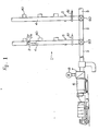
- FIG. 1 is a view depicting the whole of the waste collection system of a preferred embodiment of this invention.
- numeral 1 designates a waste collection system.
- This waste collection system comprises input ports 3, 3 provided at each floor of the multistorey building, vertical transport tubes 4, 4 provided for connection to the input ports 3, 3, respectively, a horizontal transport tube 5 connected to the bottom ends of the vertical transport tubes 4, 4, and laid in an approximately horizontal plane, a storage mechanism 6 connected to one end of the horizontal transport tube 5 adjacent to a waste accumulation area, a separator 7 connected to the said horizontal transport tube 5 in the vicinity of the said end thereof, and a blower 8 connected to the horizontal transport tube 5 via the separator 7.
- a waste container 2 is constructed, as shown in Figure 1, with a container body 2a of an inverted, truncated shape, and a cap 2b detachably'fixed to the upper opening of the container body 2a.
- the waste container 2 is made of inexpensive and combustible materials such as reformed used papers, and it is a throwaway type.
- said vertical transport tubes 4, 4 are hollow and cylindrical having a uniform inner diameter throughout.
- the inner diameter is a'little larger than the outer diameter of the said waste container 2. Accordingly, when the waste container 2 is housed in the vertical transport tube 4, a small gap is created between these two.
- the said horizontal tube 5 has a uniform and same inner diameter throughout as the vertical transport tube 4.
- the container body 2a of the waste container 2 is located in each room, and receives wastes therein. And, when the aid container body 2a is full, the cap 2b is fixed to the container body 2a so as to seal the waste container 2. Then, in this state, the waste is thrown away with the waste container 2 through the input port 3. Meanwhile, at the input port 3, a storage device 40 is provided which stores a plural number of waste containers 2 temporarily and automatically throws these waste containers 2 into the vertical transport tube 4 (see Figure 1)- Since this storage device 40 can accommodate a plural number of waste containers 2 temporarily, even if a lot of waste containers 2 are thrown into the input port 2 during a short time of period, these containers will be thrown in order to the vertical transport tube 4.
- the control means conducts an orderly throwing operation for the waste containers 2, so that if a large number of waste containers 2 are thrown from several floors, the waste collection system operates smoothly.
- the waste collection system has a lid of the same configuration as the wall of the said vertical transport tube 4, so that the lid closes the communication opening that connects the waste collection system to the vertical transport tubes 4 .unless the waste containers 2 are thrown into the vertical transport tubes 4.
- each vertical transport tube 4 is uniform and round.
- This construction si effective- for suppressing the noise produced by the waste containers 4 as they fall through the vertical transport tubes 4. that is to say, if the vertical transport tube 4 -does not have a uniform section, a problem rises in that a large noise is produced when the waste container 2 passes through such non-uniform portions.
- the control device as shown in Figure 16, which comprises a pressure gage 315 at the bottom end of each vertical transport tube 4, a control means 316, decelerating tubes 311a, 311b, and 311c, whose inner diameter is smaller than that of the vertical transport tube 4, and open/close valves 310a, 310b, and 310c provided at the decelerating tubes, respectively.
- the said control device controls the openings of the open/close valves 310a, 310b, and 310c in accordance with the pressure in the vertical transport tubes 4 measured by the pressure gage 315, thereby controlling the pressure below the waste container 2, controlling the dropping velocity of the waste container 2.
- the control device may include a connecting pipe 309 which communicates the said decelerating tubes 310a, 310b and 310c with the upper portions of the vertical transport tubes 4.
- a connecting pipe 309 which communicates the said decelerating tubes 310a, 310b and 310c with the upper portions of the vertical transport tubes 4.
- the said control means may include a connecting pipe 309 which communicates with the vertical tube 4 at the upper junction 307 and the lower junction 306, and an air blowing means 308 provided at an intermediate point of the connecting pipe 309.
- the air blowing means 308 sucks the air in the vertical transport tube 4 from the upper junction 307 and exhausts it from the lower junction 308. In this manner, the waste container 2 encounters a larger air resistance causing further deceleration.
- a delicate speed control is feasible by controlling the air weight flow thereof.
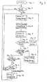
- step 1 When the built-in program of the control means starts operating (step 1), it checks whether the waste container is held or not in the storage device 40 numbered 1- N connected to the vertical transport tube (step 2). If there is no waste container 2 in the storage devices 40, the program does not give any operational instruction. On the other hand, if there is a waste container 2 in the storage device 40, the program proceeds to step 3, and among the storage devices 40 that contain the waste containers 2, only the uppermost one is driven to an operational state while the others are prohibited from throwing the waste containers into the vertical transport tube (step 4). Then, from the thus selected storage device 40, the waste container 2 is thrown away into the vertical transport tube 4 (step 5).
- each vertical transport tube 4 there is provided a waste container passage sensor made up of a light sensor at a position below the junction of the lowermost storage device 40 and the vertical transport tube.
- the program judges whether or not the waste container has passed by the said sensor within a predetermined time (step 6), and if it detects the passage of the container, the program goes forward to step 7. Otherwise, it jumps to a malfunction subroutine (step 8).
- the waste containers 2 are accommodated in the storage device 40 except the one which has been selected already. And, if any one of the storage devices 40 is full, the program goes to step 9, otherwise it goes to step 10. At step 9, the said full storage device 40 is selected, and returns to step 3, so as to throw the waste container 2 from the full storage 40. In this case, if there are a plural number of full storage devices 40, the uppermost one is selected.
- step 10 it is checked whether or not the waste container 2 is-left in the storage device 40, and if it is left, the program proceeds to step 11, otherwise, it proceeds to step 12.
- a pass partition valve 61 is provided upstream from the junction with the said horizontal transport tube 5 so as to temporarily keep the waste containers 2.
- the number of waste containers 2 kept at the pass partition valve 61 is counted, and the number counted i$ compared with the predetermined number. If the number counted is smaller than or equal to the predetermined number, the program goes to step 3 and continues the operation fo throwing the waste container 2, while if the former is larger than or equal to the latter, it goes to step 12.
- step 12 the said pass partition valve 61 is opened, moving the waste container 2 kept at the pass partition valve 61 into the horizontal transport tube 5. Then, after the completion of step 12, the program returns again to step 2.
- the waste containers 2 are thrown in order into the vertical transport tubes 4 by means of the storage devices 40, and further to the bottom ends of the vertical tubes 4.
- the vertical transport tubes 4 are, as depicted in Figures 1, 3, and 4, connected to the horizontal transport tube 5 at their bottom ends via rotating valves 60.
- the pas partition valve 61 is disposed po that the distance between the rotating valve 60 and the pass partition valve 61 is set to a value which allows for the accommodation of at least two waste containers 2 in the vertical transport tube 4 as shown in Figure 4.
- the pass partition valve 61 has a box-shaped storage space 62 which is integrally attached to the vertical transport tube 4 so as to horizontally penetrate tube 4. On the top and bottom sides of the storage space 62, slits are formed to be engaged with the vertical transport tube 4. Furthermore, in the storage space 62, a plate-like pass partition valve 61 is inserted by sliding it in the horizontal direction. Due to this construction, the pass partition valve 61 can be horizontally moved through the vertical transport tube 4 by operating an operating lever 63 attached to the said pass partition valve 61, and the waste container 2 falling in the vertical transport tube 4 can be stopped above the said rotating valve 60.
- the said rotating valve 60 includes a hollow and disc- shaped valve casing 64 which connects the vertical transport tube 4 and the horizontal transport tube 5, and a valve body 65 housed in the valve casing 64 and rotatable about the horizontal axis of the valve casing 64.
- a stock passage 66 is formed which penetrates the central portion thereof.
- This stock passage is formed in a manner such that its inner diameter is approximately equal to the inner diameter of the said vertical transport tube 4, and its length is twice as long as the length of the waste container 2.
- This rotating valve 60 can be moved between the first position at which the stock passage 66 is connected to the vertical transport tube by the rotation of the valve body 65, and the second position at which the stock passage communicates with the horizontal transport tube.
- the waste container 2 When the waste container 2 is thrown into the vertical transport tube 4 which has the above structure, it falls along the vertical transport tube and reaches the pass partition valve 61. After that, if a plural number of the waste containers 2 is thrown into the vertical transport tube 4, a plurality of waste containers 2 are accumulated at the pass partitioning valve 61.
- the valve 61 When the plural number of waste containers 2 are piled on the pass partitioning valve 61, the valve 61 is opened to drop the waste container 2 below the pass partition valve 61.
- the valve body 65 is rotated so that its stock passage 66 is directed upward to align it with the vertical transport tube 4.
- the waste container as shown in Figure 3, falls into the stock passage 66 to be stored therein.
- the valve body 65 is rotated as illustrated in Figure 4, so that the stock passage 66 is aligned with the horizontal transport tube 5, with the " bottom fo the container body 2a of the waste container 2 directed to the said air blower 8.
- the bottom end of the vertical transport tube is, as mentioned above, blocked by the circumferential surface 65a of the valve body 65.
- the said horizontal transport tube 5 is laid and drawn in an approximately horizontal plane, though, some parts thereof may be drawn in the vertical direction if it is so demanded by the building structure or the like.
- the blower has to have an output performance of a certain level.
- the travelling velocity of the waste container 2 becomes excessively high so that at the bottom end of the vertical portion, the waste container 2 might collide with the wall of the horizontal transport tube 5 and break.
- the horizontal transport tube 5 has a vertical portion, it is desirable to provide a bypass line to such a portion, which will be described below.
- a bypass line is provided which is connected to the uppermost portion and the lowermost portion of the vertical portion through which the waste container 2 is force-fed vertically downward. Due to this construction, when the waste container 2 is travelling through the vertical portion, most of the air in the horizontal transport tube 5 flows in the bypass line, and does not exert any propulsive force to the waste container 2. Hence, the velocity of the waste container 2 will not become excessive.
- FIG 9 is a view, showing the vertical portion of the horizontal transport tube 5 which is equipped with the said bypass line.
- the waste container 2 is force-fed from left to right by the air flow indicated by the arrow.
- the waste container 2 is shaped like a truncated cone, and is force-fed in a manner such that its smaller face is directed in the direction it proceeds.
- the 'horizontal transport tube 5 is mainly constituted by horizontal portions 5h and 5h which extend horizontally, vertical portions 5vu and 5vd, and an upper horizontal portion 56 which connects the vertical portions 5vu and 5vd.
- the inner diameter of the vertical portion 5vu through which the waste container 2 runs upward is smaller than that of the horizontal portion 5h. Accordingly, the - horizontal portion 5h is connected to the vertical portion 5vu via a throttled portion 71.
- the diameter of the vertical portion 5vd through which the waste container 2 runs downward is equal to that of the horizontal portion 5h, and the vertical portion 5vd is connected to the horizontal portion 5h at its bottom end. Accordingly, the upper horizontal portion 5e is connected to the following vertical portion 5vd via an enlarged portion 72. Moreover, the bypass line 73 is provided along the vertical portion 5vd. The diameter of the bypass line 73 is smaller than that of of the vertical portion 5vd, and the bypass line 73 is connected to the vertical portion 5vd at the upper and lower ends of the vertical portion 5vd.
- the waste container 2 force-fed from left to right through the horizontal " transport tube 5 first reaches the vertical portion 5vu. Since the inner diameter of the vertical portion 5vu is smaller than other portions of the horizontal transport tube, a large propulsive force is applied to the waste container 2. Therefore, it can-ascend through the vertical portion 5vu without its speed being reduced in comparison with the horizontal portion 5h. Then, the waste container 2 passes through the upper horizontal portion 5e to reach the vertical portion 5vd. Meanwhile, the air in the horizontal transport tube 5 is divided at the said vertical portion 5vd, namely into the flows through the vertical portion 5vd and the bypass line, 73. In normal operation, the weight flows thereof are approximately proportional to the areas of the sections, respectively.
- a bypass line 73 is provided to each vertical stage. And, it is acceptable to provide the bypass line 73 to connect the uppermost end and the lowermost end of the multi-stage vertical portion. Besides the vertical portion, it is also effective to provide the bypass line 73 to that segment where the waste container 2 falls diagonally downward.
- the inner diameter of the vertical portion 5vu is set to be smaller than that of the horizontal portion 5h, but it is not necessarily set to such a value. In any case, however, it goes without saying that air pressure is required for the waste container 2 to ascend through the vertical portion.
- the said valve body 65 is rotated again so as to align the stock passage with the vertical transport tube 4. And, by repeating the above operation, the waste containers 2 disposed of at various places in the building are collected and stored by the storage mechanism 6.
- step 21 it checks whether or not the waste containers 2 are stopped at the bottom ends of the vertical transport tubes numbered 1 through N, namely on the said pass partitioning valves 61 (step 22).
- the program stops and waits until the waste containers 2 are thrown into the vertical transport tubes 4 from the storage devices disposed at the said input ports.
- the program proceeds to step 23.
- one of the vertical transport tubes 4 in which the waste containers are stored is selected, and the others are kept closed by blocking the vertical transport tubes by means of the pass partitioning valves 61, to prohibit the operation thereof (step 24).
- the waste container 2 kept in the vertical transport tube 4 thus selected is thrown into the horizontal transport tube 5 (step 25).
- This throwing of the waste container 2 is performed, as depicted in Figures 3 and 4, by rotating the rotating valve 60 alternatively.
- the blower 8 is operated so as to force-feed the waste container 2 toward the said storage mechanism 6 (step 26).
- a waste container passing sensor (not shown) which is made up of a light sensor.
- the program judges whether a signal from the waste container passing sensor, which tells of the passing of the waste container 2, is transmitted or not within a predetermined time after throwing in the waste container 2 (step 27). If the signal is transmitted, it goes to step 28 while if it is not, it jumps to ⁇ a malfunction-routine (step 29).
- a'discharge valve which is attached to the said storage mechanism '6, for discharging the waste container 2 is operated so as to discharge the waste container 2 from the collection system.
- the waste containers are kept in the vertical transport tubes 4 except the one which has been previously selected, and it is judged whether or not any one of vertical transport tubes 4 is filled with waste containers 2. If a full vertical transport tube 4 is full, the program goes to step 32, otherwise it goes to step 31. At step 32, the aforesaid full vertical tube 4 is selected, and the program returns to step 23 to begin throwing of the waste containers 2 from the full vertical transport tube 4.
- step 31 it is judged whether a waste container 2 remains in the vertical transport tube 4, and if there is a container, the program returns to step 23 to continue the throwing operation of waste container 2. If not, it returns to step 22, and waits for the waste containers 2 to be thrown into the vertical transport tubes 4.
- the waste containers 2 are orderly supplied to the horizontal transport 5 from a plural number of vertical transport tubes 4.
- a measuring means such as a pressure gage for measuring the pressure in the horizontal transport tube 5, and a control means for controlling the output of the blower 8 in accordance with the said pressure
- the suction force of the said blower 8 is progressively increased, in the horizontal transport tube 5, the pressure of that portion which is closer to the blower 8 than the waste container 2 becomes smaller than that of the portion which is farther than container 2.
- the maximum pressure difference thereat is called "Pc" hereinafter.
- the pressure difference Pd across the waste container 2 then usually becomes smaller than the said Pc. This is generally because the static friction coefficient is larger than the dynamic friction coefficient.
- the maximum pressure difference Pc is considered to be a function of the total weight of the waste container 2 and the coefficient of static friction between the waste container 2 and the horizontal transport tube 5. After the waste container 2 starts moving, the propulsive force caused by the pressure difference Pd balances the dynamic friction force and the inertia force of the waste container 2. Therefore, if the dynamic friction coefficient and the static friction coefficient are stored in a memory beforehand, it is possible to calculate the total weight of. the waste container 2 from the maximum pressure difference Pc in the horizontal transport tube 5 measured by the said measuring device.
- the weight flow of the blower can be controlled based on the velocity estimated thus.
- a vertical end portion 5d is formed which stands approximately vertically.
- the inner diameter of this vertical end pipe 5d is a little larger than the maximum diameter of the waste container 2.
- a takeoff valve 130 is provided at the lower end thereof.
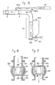
- This takeoff valve 130 as shown in Figures 6 and 7, is constructed such that a spherical valve body 132 is rotatably accommodated in a hollow-sphere-shaped valve casing 131.
- a guide opening 133 is formed for the waste container 2, which is connected to the vertical end portion 5d of the aforesaid horizontal transport tube 5 at its top while a waste container discharge opening 134 is formed at the bottom.
- the inner diameters of the guide opening 133 and the discharge opening 134 are approximately equal to the inner diameter of the horizontal transport tube 5.
- a storage space 136 is provided within the valve body 132, which can store the waste container 2.
- This storage space is formed by boring the central portion fo the valve body like a cavity while leaving the bottom plate 135.
- This storage space 136 is formed such that its inner diameter is approximately equal to the inner diameter of the horizontal transport tube 5, its depth is a little more than the height of the waste container 2, and it can communicate with the said guide opening 133 or the discharge opening 134 since its top is open.
- the valve body 132 is also constructed so that it rotates in the said valve body 131 while maintaining the airtightness therewith. Thus, when the valve body 132 rotates, the air flow between the guide opening 133 and the discharge opening 134 is blocked by the valve body 132. Accordingly, the airtightness of the said horizontal transport tube 5 is always secured.
- a drive mechanism for rotating the valve body 132 it is preferable to provide a drive source such as a motor, but it is satisfactory to operate it manually, for example with a lever from outside the valve casing 131.
- inlet tubes 140a and 140b are formed along the longitudinal direction of the horizontal tube 5 in turn.
- These inlet tubes 140a and 140b serve as the inlets of the inlet line 141 of the said blower 8 (not shown in Figure 5), so that the air in the horizontal transport tube 5 is sucked through the inlet pipes 140a and 140b'due to the suction force of the blower 8.
- the inlet pipes 140a and 140b are provided at an interval larger than the length of the waste container 2.
- an air guide pipe 142 is provided adjacent thereto and opened to the vertical tube 5d at one end. The other end of the air guide pipe. 142 is opened to the atmosphere. And, in the air guide pipe 142, a control valve 143 is provided for controlling the weight flow of the air flowing therein.
- a pressure measuring means 144 is disposed at the vertical end tube 5d for measuring the pressure in the tube. This pressure measuring means 144 is provided in order to control the force-feeding speed of the waste container 2 by measuring the pressure in the horizontal transport tube 5 as mentioned above.
- the waste container 2 thrown in the horizontal transport tube 5 is sucked by the functioning of the blower 8 so that it is force-fed toward the end of the horizontal transport tube 5, namely toward the vertical end tube 5d.
- the suction force Q which serves as the carrying force for the waste container 2 is approximately equal to the suction force generated in the inlet line of the blower 3.
- the suction force is only applied via the inlet pipe 140b closer to the blower 8 than the waste container 2.
- the majority of the air flows through the inlet tube 140a which the container has already passed through.
- the suction force exerted on the waste container 2 is decreased by a large magnitude.
- the waste container 2 that has further passed through 140b reaches the said vertical end tube 5d and falls therethrough.
- the vertical end tube 5 is formed so that its inner diameter is a little larger than the outer diameter of the waste container 2, and its lower end is closed by the said takeoff valve 130.
- the air therebelow is compressed so that it functions as a buffer area to reduce the dropping velocity of the waste container 2, so that it lands gently without breaking.
- the said control valve 143 is opened when the waste container 2 is falling in the said vertical end tube 5d, a pressure difference is generated across the waste container 2 at its top and bottom due to the function of the said blower 8, so that the waste container 2 is subjected to upward pressure. Meanwhile, the suction force of the blower 8 is controlled based on the total weight of the waste container 2-. Therefore, the waste container 2 in the vertical end tube 5d is exposed to a large upward pressure if its total weight is large. Furthermore, by controlling the degree of opening of the said control valve 143, it is feasible to control the waste container 2 so that it lands gently on the takeoff valve 130. When the waste container 2 approaches the said vertical end tube 5d, the storage space 136 and the guide opening 133 are connected to each other by directing the valve body 132 of the takeoff valve 130 upward, so that the waste container 2 can be stored in the storage space 136.
- the storage space 136 and the discharge opening 134 are connected to each other by rotating the valve body 132 at 180 degrees, thereby discharging the waste container 2 from the discharge opening 134.
- the outer surface of the valve body 132 and the inner surface of the valve casing 131 are kept airtight, the airtightness in the horizontal transport tube 5 is also maintained.
- the said vertical end tube 5d may be equipped with a sorting means as follows. Namely, a sorting means that comprises a valve for opening and closing the bottom opening of the vertical end tube 5d, a sensor for identifying the color fo the waste container 2, and a switching means for selectively conveying the waste containers 2 to the plural number of accumulation places based on an identification signal from the said sensor.
- a sorting means that comprises a valve for opening and closing the bottom opening of the vertical end tube 5d, a sensor for identifying the color fo the waste container 2, and a switching means for selectively conveying the waste containers 2 to the plural number of accumulation places based on an identification signal from the said sensor.
- Figure 11 and 12 are views depicting one embodiment of the sorting means, respectively.
- the first valve 80 Provided in the vicinity of the bottom end of the vertical end tube 5d, is the first valve 80 that can open and close the said vertical end tube 5d.
- a valve storage 81 and a valve drive means 82 Disposed in the vicinity of the first valve 80, are a valve storage 81 and a valve drive means 82.
- the first valve is stored inside the valve storage 81 when it is in the open mode, so that the waste container 2 can pass therethrough.
- the first valve 80 When the first valve 80 is in the closed mode, the waste container 2 is supported by the first valve 80 which blocks the bottom end of the vertical end tube 5d.
- the valve drive means 82 can move the first valve 80 to the said open position or close position.
- a second valve 83 is provided above the first valve 80, namely at a position spaced higher than the height of the waste container 2, and other elements that have the same structure as the first valve 80, the valve storage 81, and the valve drive means 82.
- a color identification sensor 84 Provided at a position from which the cap 2b of the waste container 2 can be seen is a color identification sensor 84.
- This color identification sensor 84 can identify the color of the cap 2b when the waste container 2 is supported to rest by the first valve 80.
- a carrying means 85 Provided under the vertical end tube 5d is a carrying means 85 that can be moved in both directions, i.e., from left to right or vice versa in Figure 11. This carrying means 85 is connected to a drive means 86 which provides the driving power.
- the drive means 86 is connected to a control mechanism 87 so as to be actuated by a signal therefrom.
- the control mechanism 87 is constructed in a manner such that it can receive the identification signal transmitted from the said color identification sensor 84 and send the drive signal to the said valve drive means 82.
- the second valve 83 When the waste container 2 reaches the second valve 83, the second valve 83 is opened so that one waste container 2 is dropped downward. At this time, the first valve 80 is in the closed mode.
- the color identification sensor 84 identifies the color (the part'indicated by oblique lines in Figure 12) of the cap 2b of the waste container 2, and sends the identification to the control mechanism 87.
- the caps of the waste containers 2 are given different colors in accordance with the contents, for example incombustible substances and combustible substances are given different colors.
- the control mechanism 87 selects the direction of the carrying device 85 based on the identification signal, and sends a signal to the valve drive mechanism 82 to close the first valve 80.
- the waste container 2 drops onto the carrying means 85 so that it is carried to a predetermined position.
- the waste containers 2 are automatically sorted, carried to the predetermined positions, and accumulated by providing the sorting means constructed as described above. That is to say, the labor required for carrying and classifying waste is considerably reduced.
- the sorting means is provided at the said vertical end 5d. However, it is not necessarily provided at the vertical end 5d. Namely as shown in Figure 13, it would be provided in the vicinity of the bottom end of each vertical transport tube 4. In this case, it is possible to selectively convey the waste container 2 to one of a plural number of horizontal tubes by the carrying means 85. If those plural mumber of horizontal transport tubes 5 are provided to connect to different accumulation areas, respectively, the waste containers can be sorted and automatically collected to the accumulation areas by the sorting means of the aforesaid type. And, the said takeoff valve 130 would serve as the said first valve 80. In this case, the said color identification sensor 84 sorts the color the waste container 2 held by the takeoff valve 130. Furthermore, the said second valve can be omitted.
- the waste collection system and the method therefor of the present invention would include a blockage-freeing mechanism and a blockage-freeing method, respectively, as follows. That is to say, an apparatus and a method therefor by which when a waste container 2 blocks the horizontal transport tube 5, air is blown back to free the blockage, and the air is then supplied forward to force-feed the container in the horizontal transport tube 5. These will be described in depth with Figure 14.
- FIG 14 is a conceptual view showing a schematic construction of the waste collection system.
- numeral 201 designates a horizontal transport tube, 202 a waste container which is force fed, usually from left to right, in the horizontal transport tube 201, and 203 a separator to pick out the waste container 202.
- the waste container 202 is shaped like a truncated cone, and it is force-fed with the end face of the smaller diameter directed to the right, i.e., toward the accumulation area.
- the waste container 202 blocks the horizontal. transport tube 201 in Figure 14.
- the accumulation area side end of the horizontal transport tube 201 is connected to the inlet of an 'air blower 206 via tubes 204 and 205, and to the outlet of the blower 206, tubes 207, 208, and 209 are connected in turn.
- tubes 207, 208, and 209 are connected at the tip of tube 209.
- a bypass pipe 211 is provided so that it connects the junction of the horizontal transport tube 201 and the tube 204 and the junction of the tubes 208 and 209.
- a tube 212 is connected, at the end of which is an exhaust 213 opened to the outside.
- the valves 214, 215, 216, and 217 respectively are disposed.
- a vacuum breaker 218 is connected.
- a discharge breaker 219 is connected.
- valves 214 and 215 are opened while the valves 216 and 217 are closed, and the blower 206 is operated, so that the air in the horizontal transport tube 201 is sucked in, as shown by the solid - arrow in Figure 14, through tubes 204, 205, 207, 208 and 209 to be discharged from the discharge port 210, and the waste container 202 is force-fed by the air flow generated thereupon as shown by the solid arrow.
- valves 214 and 215 are closed while the valves 216 and 217 are opened, and the blower is driven, so that the air is sucked from outside through the inlet opening 2.13 to be supplied in the horizontal transport tube 21 via the tubes 212, 205, 207, 208, and 211, as shown by the broken arrow in Figure 14, to generate the air flow in the opposite direction relative to the previous case.
- This operation pushes the blocking waste container 202 backward, releasing the blockage.
- valves 214, 215, 216, and 217 are set back to the normal mode to start the normal operation.
- the blockage in the horizontal transport tube 201 can be freed by an easy operation, namely by just switching valves.
- FIG. 15 The construction of the pipeline is not limited to the one described above.
- an inlet tube 220 and an exhaust tube 221 of the blower 206 are connected to the horizontal transport tube 201 via valves 222 and 223, respectively.
- a bypass pipe 224 is provided between the inlet tube 220 and the exhaust tube 221, and at intermediate points of the,bypass pipe 224 are provided an inlet/outlet port 225, and valves 226 and 227.
- numeral 230 denotes a dust collector disposed at an intermediate point of the inlet tube 220, and 230 denotes a noise eliminator at the outlet tube 221.
- valves 222 and 226 are opened and valves 223 and 227 are closed so as to flow the air as indicated by the solid arrow in Figure 15.
- the valves 223 and 227 are opened while valves 222 and 226 are closed, letting the air flow in the direction indicated by the broken arrow.
- the open end which is utilized as an exhaust opening during normal operation, is utilized as an inlet opening.
- the above effect is obtained by providing another blower for supplying air backward which is only used when there is a blockage, i.e., when a blockage occurs, the blower which supplies the air forward is stopped while the back-blowing blower is operated.
- a blower which can be operated in both normal and reverse modes would be employed, so that when a blockage occurs, the blower is operated in the reverse mode, obtaining the same effect as above.
Landscapes
- Engineering & Computer Science (AREA)
- Architecture (AREA)
- Civil Engineering (AREA)
- Structural Engineering (AREA)
- Refuse Collection And Transfer (AREA)
Applications Claiming Priority (12)
| Application Number | Priority Date | Filing Date | Title |
|---|---|---|---|
| JP30599186A JPS63160905A (ja) | 1986-12-22 | 1986-12-22 | ごみ容器の搬送システム |
| JP305991/86 | 1986-12-22 | ||
| JP155809/87 | 1987-06-23 | ||
| JP62155809A JP2620082B2 (ja) | 1987-06-23 | 1987-06-23 | ごみ容器搬送システム |
| JP170076/87 | 1987-07-08 | ||
| JP62170071A JP2544931B2 (ja) | 1987-07-08 | 1987-07-08 | ごみの集廃システム |
| JP170071/87 | 1987-07-08 | ||
| JP170077/87 | 1987-07-08 | ||
| JP17007587A JPS6413309A (en) | 1987-07-08 | 1987-07-08 | Sorting device for refuse container |
| JP17007787A JPS6413311A (en) | 1987-07-08 | 1987-07-08 | Method for removing clogging in conveyance pipe of refuse container conveyance system |
| JP170075/87 | 1987-07-08 | ||
| JP62170076A JP2544932B2 (ja) | 1987-07-08 | 1987-07-08 | ゴミ容器搬送システムのゴミ容器回収部機構 |
Publications (2)
| Publication Number | Publication Date |
|---|---|
| EP0297145A1 true EP0297145A1 (de) | 1989-01-04 |
| EP0297145A4 EP0297145A4 (de) | 1990-03-27 |
Family
ID=27553165
Family Applications (1)
| Application Number | Title | Priority Date | Filing Date |
|---|---|---|---|
| EP19880900134 Withdrawn EP0297145A4 (de) | 1986-12-22 | 1987-12-22 | Verfahren und system zum sammeln von müll. |
Country Status (3)
| Country | Link |
|---|---|
| US (1) | US4995765A (de) |
| EP (1) | EP0297145A4 (de) |
| WO (1) | WO1988004640A1 (de) |
Cited By (8)
| Publication number | Priority date | Publication date | Assignee | Title |
|---|---|---|---|---|
| GB2226001A (en) * | 1988-12-16 | 1990-06-20 | Shimizu Construction Co Ltd | Refuse conveyor system |
| EP0596750A1 (de) * | 1992-11-05 | 1994-05-11 | Shinmaywa Industries, Ltd. | Saugförderanlage für Abfall |
| CN101903267A (zh) * | 2007-12-21 | 2010-12-01 | 马里凯普有限公司 | 用于气动物料运送系统中的方法及设备 |
| EP2695833A1 (de) * | 2012-08-09 | 2014-02-12 | Ros Roca Envirotec, S.L. | Verfahren zum pneumatischen Transport von Müll |
| WO2017151038A1 (en) * | 2016-03-03 | 2017-09-08 | Logiwaste Ab | Vacuum waste collection system and a method for handling wastes |
| CN110395503A (zh) * | 2019-07-30 | 2019-11-01 | 重庆翰博光电有限公司 | 生产线垃圾自动收集装置 |
| US10625936B2 (en) | 2015-03-09 | 2020-04-21 | Maricap Oy | Method and apparatus in a pneumatic pipe transport system for material, and a conveying system for wastes |
| PL441801A1 (pl) * | 2022-07-21 | 2024-01-22 | Politechnika Rzeszowska im. Ignacego Łukasiewicza | Instalacja pneumatyczna do dystrybucji i segregacji śmieci w budynku wielokondygnacyjnym oraz sposób dystrybucji i segregacji śmieci w budynku wielokondygnacyjnym z wykorzystaniem tej instalacji |
Families Citing this family (42)
| Publication number | Priority date | Publication date | Assignee | Title |
|---|---|---|---|---|
| US5072833A (en) * | 1989-05-10 | 1991-12-17 | Eac Systems, Inc. | Method of collecting recyclable materials |
| US5226775A (en) * | 1990-12-24 | 1993-07-13 | L. B. Bohle Pharmatechnik Gmbh | Method of and apparatus for conveying and storing tablets, pills and like products |
| US5441160A (en) * | 1991-04-29 | 1995-08-15 | Environmental Products Corporation | Method of collecting densified commodities using a mobile multi-compartment commodity collection and storage assembly |
| US5316152A (en) * | 1992-07-06 | 1994-05-31 | Ross James A | High rise recycling system |
| JP2795306B2 (ja) * | 1994-03-18 | 1998-09-10 | 大豊工業株式会社 | 軸受装置 |
| US5727455A (en) * | 1996-04-01 | 1998-03-17 | Yerman; Arthur J. | Automatic syringe destruction system and process |
| KR19980077546A (ko) * | 1997-04-21 | 1998-11-16 | 한스 스트롬 | 쓰레기 배출 방법 및 장치 |
| US6086161A (en) * | 1997-06-18 | 2000-07-11 | Nimble Bicycle Company | High performance broad application wheel |
| US6322295B1 (en) | 1999-11-18 | 2001-11-27 | Dino Gabriele | Pneumatic apparatus and method for transporting irregularly-shaped objects |
| US6564924B2 (en) * | 2001-07-09 | 2003-05-20 | Bryan Street | Apparatus and method for positioning randomly oriented articles in the same orientation |
| US6712561B1 (en) | 2002-09-23 | 2004-03-30 | Frederick M. Valerino, Sr. | Disposal of sharps in a healthcare environment |
| US8560459B2 (en) | 2005-11-17 | 2013-10-15 | Casella Waste Systems, Inc. | Methods and facilities for a municipal solid waste management system |
| US20070219862A1 (en) * | 2006-03-20 | 2007-09-20 | Casella Waste Systems, Inc. | System and method for identifying and processing recyclables |
| US20070260466A1 (en) * | 2006-03-20 | 2007-11-08 | Casella Waste Systems, Inc. | System and methods for a recycling program |
| KR101321735B1 (ko) | 2006-06-09 | 2013-10-29 | 엔박 에이비 | 쓰레기 관리 |
| US20080010197A1 (en) * | 2006-07-10 | 2008-01-10 | Scherer Christopher M | Enhanced municipal bidding model |
| US20080086411A1 (en) * | 2006-10-04 | 2008-04-10 | Olson Robert A | REC credit distribution system and method |
| US20080273955A1 (en) * | 2007-05-02 | 2008-11-06 | International Truck Intellectual Property Company, Llc. | Refuse collection device and disposal method for public transportation vehicles |
| FI122682B (fi) * | 2007-09-18 | 2012-05-31 | Maricap Oy | Jätteiden siirtojärjestelmä |
| FI123782B (fi) | 2007-12-21 | 2013-10-31 | Maricap Oy | Menetelmä ja laitteisto pneumaattisessa materiaalinsiirtojärjestelmässä |
| FI124507B (fi) * | 2007-12-21 | 2014-09-30 | Maricap Oy | Menetelmä pneumaattisessa materiaalinsiirtojärjestelmässä ja pneumaattinen materiaalinsiirtojärjestelmä |
| US20100296880A1 (en) * | 2007-12-21 | 2010-11-25 | Sundholm Goeran | Pneumatic material conveying system |
| FI124408B (fi) * | 2007-12-21 | 2014-08-15 | Maricap Oy | Menetelmä ja laitteisto pneumaattisessa materiaalinsiirtojärjestelmässä |
| FI20085143A7 (fi) * | 2007-12-21 | 2009-06-22 | Maricap Oy | Menetelmä ja laitteisto pneumaattisessa materiaalinsiirtojärjestelmässä |
| ES2838149T3 (es) * | 2008-03-17 | 2021-07-01 | Urban Refuse Dev Slu | Sistema de control de basuras para conductos de basura |
| GB2464272B (en) * | 2008-10-07 | 2011-02-02 | Advanced Mfg Control Systems Ltd | A waste management system for associating refuse bins to corresponding users |
| US20110076104A1 (en) * | 2009-09-29 | 2011-03-31 | Gas Technology Institute | Pipeline pod transport method |
| ES2998033T3 (en) * | 2010-03-04 | 2025-02-18 | Envac Ab | Waste emptying control |
| FI125741B (fi) * | 2012-07-02 | 2016-01-29 | Maricap Oy | Menetelmä ja laitteisto materiaalin käsittelemiseksi pneumaattisessa materiaalinkäsittelyjärjestelmässä |
| FI124487B (fi) * | 2013-01-25 | 2014-09-30 | Maricap Oy | Menetelmä ja laitteisto jätemateriaalin syöttämiseksi syöttökuilusta |
| FI125194B (fi) * | 2013-07-30 | 2015-06-30 | Maricap Oy | Menetelmä ja laitteisto jätemateriaalin syöttämiseksi ja käsittelemiseksi |
| FI124837B (fi) * | 2013-07-30 | 2015-02-13 | Maricap Oy | Menetelmä ja laitteisto jätemateriaalin syöttämiseksi ja käsittelemiseksi |
| FI127098B (fi) * | 2016-01-07 | 2017-11-15 | Maricap Oy | Menetelmä, laitteisto ja järjestelmä jätemateriaalin käsittelemiseksi |
| US9539178B1 (en) | 2016-05-17 | 2017-01-10 | Fredrick M. Valerino, SR. | Medical object distribution system and method |
| US9549784B1 (en) | 2016-05-17 | 2017-01-24 | Fredrick M. Valerino, SR. | Sharps disposing system and method |
| JP7116975B2 (ja) * | 2016-08-31 | 2022-08-12 | フロイント産業株式会社 | 逸脱処理装置及び逸脱処理方法 |
| FI130019B (fi) * | 2018-10-22 | 2022-12-30 | Maricap Oy | Menetelmä materiaalin käsittelemiseksi materiaalinsiirtojärjestelmässä, erotinlaitejärjestely ja materiaalinsiirtojärjestelmä |
| FI20197011A1 (fi) * | 2019-01-25 | 2020-07-26 | Maricap Oy | Menetelmä ja laitteisto materiaalin syöttämiseksi ja siirtämiseksi |
| CN110745462A (zh) * | 2019-05-05 | 2020-02-04 | 北京金茂盛源科技发展有限责任公司 | 一种生活垃圾/医疗废物/污被服缓降物流系统 |
| US11999577B2 (en) | 2019-11-18 | 2024-06-04 | George Archambault | Methods and systems for managing airflow in conduits and pneumatic tubes |
| US10919702B1 (en) * | 2020-04-29 | 2021-02-16 | Eugene Zoltan Berta | Aerial roof height item receiving chute |
| US11565892B2 (en) | 2020-07-08 | 2023-01-31 | Trans-Vac Systems LLC | Methods and systems for operation of a vacuum transport system |
Family Cites Families (19)
| Publication number | Priority date | Publication date | Assignee | Title |
|---|---|---|---|---|
| BE655048A (de) * | 1963-10-31 | |||
| JPS434329Y1 (de) * | 1965-03-30 | 1968-02-24 | ||
| GB1199917A (en) * | 1966-07-29 | 1970-07-22 | Centralsug Ab | Conveyance of Material Requiring Hygienic Disposal |
| GB1435611A (en) * | 1972-08-15 | 1976-05-12 | Centralsug Ab | System of domestic refuse |
| FR2213396A1 (de) * | 1973-01-10 | 1974-08-02 | Bonnet Daniel | |
| DE2407482A1 (de) * | 1974-02-16 | 1975-08-28 | Heinz Boerner | Vertikal- und horizontal-transportmittel-system zur muell- und schmutzwaescheentsorgung in wohn-, geschaefts-, krankenhaus- und industrie-anlagen, hotels, sanatorien, kurzentren, feriendoerfern, altersheimen und aehnlichem |
| DK137634B (da) * | 1975-03-21 | 1978-04-10 | Bruun & Soerensen As | Skraldsugeanlæg. |
| US4076321A (en) * | 1976-12-06 | 1978-02-28 | Eastern Cyclone Industries, Inc. | Electronic control system for operating a pneumatic trash linen conveying network |
| US4240769A (en) * | 1979-07-12 | 1980-12-23 | Octavio Diaz | Solid waste disposing system |
| GB2143787B (en) * | 1983-07-14 | 1986-09-03 | Lamson D D Plc | Pneumatic conveying system |
| JP2544932B2 (ja) * | 1987-07-08 | 1996-10-16 | 新明和工業株式会社 | ゴミ容器搬送システムのゴミ容器回収部機構 |
| JPS6413309A (en) * | 1987-07-08 | 1989-01-18 | Shin Meiwa Ind Co Ltd | Sorting device for refuse container |
| JP2620082B2 (ja) * | 1987-06-23 | 1997-06-11 | 新明和工業株式会社 | ごみ容器搬送システム |
| JPS6413311A (en) * | 1987-07-08 | 1989-01-18 | Shin Meiwa Ind Co Ltd | Method for removing clogging in conveyance pipe of refuse container conveyance system |
| JP2620083B2 (ja) * | 1987-06-23 | 1997-06-11 | 新明和工業株式会社 | ごみ容器搬送システム |
| JPS6413306A (en) * | 1987-07-08 | 1989-01-18 | Shin Meiwa Ind Co Ltd | Conveyance device for refuse container |
| JPS6413307A (en) * | 1987-07-08 | 1989-01-18 | Shin Meiwa Ind Co Ltd | Refuse conveyance device |
| JP2501837B2 (ja) * | 1987-08-27 | 1996-05-29 | 新明和工業株式会社 | ゴミ容器の往復搬送システム |
| JPH0528174A (ja) * | 1991-07-22 | 1993-02-05 | Toyota Autom Loom Works Ltd | 荷役作業指示システム |
-
1987
- 1987-12-22 WO PCT/JP1987/001015 patent/WO1988004640A1/ja not_active Ceased
- 1987-12-22 EP EP19880900134 patent/EP0297145A4/de not_active Withdrawn
- 1987-12-22 US US07/207,041 patent/US4995765A/en not_active Expired - Fee Related
Cited By (11)
| Publication number | Priority date | Publication date | Assignee | Title |
|---|---|---|---|---|
| GB2226001A (en) * | 1988-12-16 | 1990-06-20 | Shimizu Construction Co Ltd | Refuse conveyor system |
| US5000641A (en) * | 1988-12-16 | 1991-03-19 | Shimizu Construction Co., Ltd. | Refuse conveyor system |
| GB2226001B (en) * | 1988-12-16 | 1992-10-28 | Shimizu Construction Co Ltd | Refuse conveyer system |
| EP0596750A1 (de) * | 1992-11-05 | 1994-05-11 | Shinmaywa Industries, Ltd. | Saugförderanlage für Abfall |
| CN101903267A (zh) * | 2007-12-21 | 2010-12-01 | 马里凯普有限公司 | 用于气动物料运送系统中的方法及设备 |
| EP2695833A1 (de) * | 2012-08-09 | 2014-02-12 | Ros Roca Envirotec, S.L. | Verfahren zum pneumatischen Transport von Müll |
| US10625936B2 (en) | 2015-03-09 | 2020-04-21 | Maricap Oy | Method and apparatus in a pneumatic pipe transport system for material, and a conveying system for wastes |
| WO2017151038A1 (en) * | 2016-03-03 | 2017-09-08 | Logiwaste Ab | Vacuum waste collection system and a method for handling wastes |
| CN110395503A (zh) * | 2019-07-30 | 2019-11-01 | 重庆翰博光电有限公司 | 生产线垃圾自动收集装置 |
| PL441801A1 (pl) * | 2022-07-21 | 2024-01-22 | Politechnika Rzeszowska im. Ignacego Łukasiewicza | Instalacja pneumatyczna do dystrybucji i segregacji śmieci w budynku wielokondygnacyjnym oraz sposób dystrybucji i segregacji śmieci w budynku wielokondygnacyjnym z wykorzystaniem tej instalacji |
| PL248455B1 (pl) * | 2022-07-21 | 2025-12-15 | Politechnika Rzeszowska Im Ignacego Lukasiewicza | Instalacja pneumatyczna do dystrybucji i segregacji śmieci w budynku wielokondygnacyjnym |
Also Published As
| Publication number | Publication date |
|---|---|
| WO1988004640A1 (fr) | 1988-06-30 |
| EP0297145A4 (de) | 1990-03-27 |
| US4995765A (en) | 1991-02-26 |
Similar Documents
| Publication | Publication Date | Title |
|---|---|---|
| US4995765A (en) | Method of collecting wastes and system therefor | |
| US4013551A (en) | Device for sorting of goods | |
| US4993882A (en) | Waste collection method | |
| US3490813A (en) | Conveyance of material requiring hygienic disposal | |
| US5000641A (en) | Refuse conveyor system | |
| JP6686171B1 (ja) | 清掃ロボットのための清掃ビン | |
| JP2013503798A (ja) | ごみシュートに関連する方法と装置 | |
| CN106395203A (zh) | 环保型封闭式垃圾自动收集系统 | |
| JP7528094B2 (ja) | 材料を供給し、搬送するための方法および装置 | |
| GB2290039A (en) | Waste disposal chute for multi-storey building | |
| CN106697690A (zh) | 环保型小型化垃圾自动收集系统 | |
| JPH07116824B2 (ja) | ダストシュート | |
| JP2544931B2 (ja) | ごみの集廃システム | |
| US4244717A (en) | System for collecting solid particles entrained in a gas stream | |
| JPH0466402A (ja) | 高層ビルのごみ収集装置 | |
| JPH07247005A (ja) | ごみ分離貯留装置 | |
| JP2702506B2 (ja) | バケット搬送システムにおける着地制御装置 | |
| JP2797741B2 (ja) | ゴミ搬送装置 | |
| JPH01275303A (ja) | 廃棄物収集装置の投入装置 | |
| JP2558484Y2 (ja) | 高層ビルのごみ容器輸送装置 | |
| JPS6016562Y2 (ja) | ごみの空気輸送装置におけるごみ投入口装置 | |
| JPS63160904A (ja) | ゴミ容器の落下速度制御方法 | |
| JP2537047Y2 (ja) | ゴミ搬送装置 | |
| JP2501837B2 (ja) | ゴミ容器の往復搬送システム | |
| FI77628C (fi) | Sopbehaollare anordnad foer toemning med hjaelp av vakuum. |
Legal Events
| Date | Code | Title | Description |
|---|---|---|---|
| PUAI | Public reference made under article 153(3) epc to a published international application that has entered the european phase |
Free format text: ORIGINAL CODE: 0009012 |
|
| AK | Designated contracting states |
Kind code of ref document: A1 Designated state(s): DE GB SE |
|
| 17P | Request for examination filed |
Effective date: 19881110 |
|
| A4 | Supplementary search report drawn up and despatched |
Effective date: 19900327 |
|
| 17Q | First examination report despatched |
Effective date: 19920309 |
|
| STAA | Information on the status of an ep patent application or granted ep patent |
Free format text: STATUS: THE APPLICATION IS DEEMED TO BE WITHDRAWN |
|
| 18D | Application deemed to be withdrawn |
Effective date: 19930611 |