EP0317285B1 - Stranggiessvorrichtung mit endlosen Raupenkokillenbändern - Google Patents
Stranggiessvorrichtung mit endlosen Raupenkokillenbändern Download PDFInfo
- Publication number
- EP0317285B1 EP0317285B1 EP88310809A EP88310809A EP0317285B1 EP 0317285 B1 EP0317285 B1 EP 0317285B1 EP 88310809 A EP88310809 A EP 88310809A EP 88310809 A EP88310809 A EP 88310809A EP 0317285 B1 EP0317285 B1 EP 0317285B1
- Authority
- EP
- European Patent Office
- Prior art keywords
- mould
- run
- carriers
- blocks
- endless track
- Prior art date
- Legal status (The legal status is an assumption and is not a legal conclusion. Google has not performed a legal analysis and makes no representation as to the accuracy of the status listed.)
- Expired - Lifetime
Links
Images




Classifications
-
- B—PERFORMING OPERATIONS; TRANSPORTING
- B22—CASTING; POWDER METALLURGY
- B22D—CASTING OF METALS; CASTING OF OTHER SUBSTANCES BY THE SAME PROCESSES OR DEVICES
- B22D11/00—Continuous casting of metals, i.e. casting in indefinite lengths
- B22D11/04—Continuous casting of metals, i.e. casting in indefinite lengths into open-ended moulds
-
- B—PERFORMING OPERATIONS; TRANSPORTING
- B22—CASTING; POWDER METALLURGY
- B22D—CASTING OF METALS; CASTING OF OTHER SUBSTANCES BY THE SAME PROCESSES OR DEVICES
- B22D11/00—Continuous casting of metals, i.e. casting in indefinite lengths
- B22D11/06—Continuous casting of metals, i.e. casting in indefinite lengths into moulds with travelling walls, e.g. with rolls, plates, belts, caterpillars
- B22D11/0608—Continuous casting of metals, i.e. casting in indefinite lengths into moulds with travelling walls, e.g. with rolls, plates, belts, caterpillars formed by caterpillars
-
- B—PERFORMING OPERATIONS; TRANSPORTING
- B22—CASTING; POWDER METALLURGY
- B22D—CASTING OF METALS; CASTING OF OTHER SUBSTANCES BY THE SAME PROCESSES OR DEVICES
- B22D11/00—Continuous casting of metals, i.e. casting in indefinite lengths
- B22D11/06—Continuous casting of metals, i.e. casting in indefinite lengths into moulds with travelling walls, e.g. with rolls, plates, belts, caterpillars
Definitions
- the present invention relates to a continuous casting machine of endless track type and relates to that type of such machine which includes a plurality of mould blocks and associated carriers connected to form two endless tracks arranged one above the other, the endless tracks having respective substantially horizontal runs which cooperate to define a mould cavity and, in use, are moved in the same direction, each endless track having a run which extends substantially vertically from the upstream end of the mould cavity and a further run which is inclined to the horizontal and extends in the direction of movement of the said runs from the downstream end of the mould cavity.
- Figure 1 is a diagrammatic side elevation of a conventional endless track type continuous casting machine. Such a machine is disclosed in JP-A-60240356.
- a plurality of mould blocks 1 are interconnected to form two mould assemblies 2 in the form of endless tracks.
- the two mould assemblies 2 are disposed one above the other with respective runs adjacent to one another to define a mould cavity 3.
- a tundish nozzle 5 extends from the bottom of a tundish 4 into the upstream end of the mould cavity 3.
- melt is poured into the tundish 4 and is supplied through the tundish nozzle 5 into the mould cavity 3 defined by the upper and lower mould assemblies 2 which are moved in the same direction by respective driving and idle rolls 6 and 7.
- the melt is cooled by the mould blocks to solidify into a casting 8 which is discharged from the downstream end of the continuous casting machine.
- each mould assembly 2 is constituted by the return path of the mould assembly 2, ie. the path of the mould blocks between the downstream and upstream end of the mould cavity, which is relatively short so that there is a tendency for the mould blocks 1 not to be sufficiently cooled by the time they return to the upstream end of the mould cavity 3.
- This lack of cooling can result in insufficient solidification of the molten metal and this in failure of the continuous casting operation.
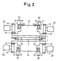
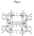
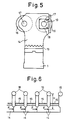
- JP-B-4626628 discloses a continuous casting machine as shown in Figures 2 to 6 in which Figure 2 is a view similar to Figure 1, Figures 3 and 4 are sectional views on the lines III-III and IV-IV, respectively in Figure 2, Figure 5 is a detailed view of a mould block and its carrier of the machine of Figures 2 to 4 and Figure 6 is a schematic view illustrating the arrangements of the mould blocks and their carriers.
- This casting machine is of the generic type referred to above and again comprises upper and lower mould assemblies 2, each comprising a plurality of mould blocks 1 interconnected in the form of an endless track, disposed in vertically opposing relationship to define the mould cavity 3.
- Each endless track defines relatively long inclined and horizontal cooling zones 9 and 10 between the downstream and upstream ends of the mould cavity 3, as shown in Figure 2.
- Each mould assembly 2 is driven by gears 12 connected to be driven by a mould assembly driving system and is braked at the downstream portion of the mould cavity 3 by a gear 13.
- Such braking of the mould assemblies 2 contributes to preventing melt from leaking through gaps between the mould blocks 1 in the runs of the endless tracks defining the mould cavity 3.
- each mould block 1 is securely joined to a carrier 14 which on each side has a rack 15 in mesh with the gears 12 and 13 and two wheels 16 for engagement with the gear 12′, as shown in Figure 5.
- One of the two wheels 16 is directly supported by the carrier 14 via a shaft 17 while the other wheel 16 is indirectly supported thereby via a shaft 17 received in a bearing box 19 which is fitted into a groove 18 defined in the carrier 14 for sliding movement in the direction of movement of the mould blocks 1 and which is also supported by an adjacent carrier.
- the shaft 17 which is directly supported by the carrier 14 is provided with a bearing box 19 which is of the same construction as the bearing box 19 described above and which is slidably fitted into a groove 18 of an adjacent carrier 14 in front of it or behind it.
- the shaft 17 which is supported via the bearing box 19 by the carrier 14 is directly supported on an adjacent carrier 14 in front of it or behind it.
- the carriers 14 are sequentially interconnected so that the mould blocks 1 are interconnected in the form of an endless track as described above.
- Each frame 20 is formed with an endless groove 21 in which the wheels 16 are rotatably received.
- the endless track mould assemblies 2 are driven by motors 22 and provided with brakes 23.
- the side surfaces of the mould cavity are afforded by side dam blocks interposed between the upper and lower opposing mould blocks 1 and adapted to move in synchronism with the mould blocks.
- the motors 22 are energised to drive the mould blocks 1 through the gears 12 and the racks 15 and the side dam blocks 24 are also driven in synchronism with their associated mould blocks 1.
- the brakes 23 are also energised to brake the mould assemblies 2 through the gears 13 and the racks 15 such that no gaps are produced between adjacent mould blocks 1 defining the mould cavity 3. In this case, the wheels 16 roll in the grooves 21 so that the mould assemblies 2 are moved smoothly.
- Melt in the tundish 4 is supplied through the tundish nozzle 5 into the mould cavity 3 and is cooled by the mould blocks to solidify into a casting 8 which is subsequently discharged out of the casting machine.
- the mould assemblies 2 are cooled by any suitable means in the cooling zones 9 and 10 and the cooled mould blocks return to the upstream end of the mould cavity 3.
- the continuous casting machine shown in Figures 2 to 6 has relatively long cooling zones 9 and 10 so that the mould blocks are satisfactorily cooled by the time they return to the upstream end of the mould cavity 3 and consequently the continuous casting operation is not adversely affected.
- the continuous casting machine described above has, however, a problem in that the upper horizontal moulding surface of the mould cavity 3 tends to be inclined downwardly since the upper mould assembly 2 has the inclined cooling zone 9 and a vertical preheating and drying zone 11, both of which are relatively long and heavy.
- the fact that the adjacent carriers 14 are spaced apart in order to absorb thermal expansion and the adjacent mould blocks are in close contact with each other to prevent leakage of melt results in the downward force (driving force and weight) of the vertical run of the mould assembly 2 being transmitted as a pressure through the contact surfaces of the mould blocks and consequently the mould blocks may be damaged if this pressure becomes too large.
- a continuous casting machine of the type referred to above is characterised by power transmission means in engagement with the carriers of the mould blocks in the vertical run and the inclined run of the upper endless track and arranged to convert a proportion of the downward force due to the weight of the mould blocks and carriers in the vertical run into a force pushing the mould block and carriers up the inclined run.
- the weight of the mould blocks and carriers in the vertical run of the upper endless track is not permitted to act on the mould blocks and carriers in the horizontal track which partially defines the mould cavity thereby impairing their alignment and potentially damaging them but instead a proportion of the force due to their weight is transmitted directly to the inclined run of the upper endless track and converted into a force pushing the mould blocks and carriers up the inclined run.
- the power transmission means may take various forms but in the preferred embodiment it includes a first rotatable gear and a second rotatable gear which are in mesh with a rack on the carriers in the vertical run and the inclined run, respectively, of the upper endless track, sprockets mounted to rotate with the first and second rotatable gears, respectively, and an endless chain connecting the two sprockets and constraining them to rotate in unison.
- a sprocket 27 is carried by the shaft of the gear 26.
- a sprocket 28 and a gear 29 Cooperating with the inclined portion of the upper mould assembly adjacent the downstream end of the mould cavity 3 and on each side thereof are a sprocket 28 and a gear 29 carried by a single shaft.
- the gears 29 are in mesh with a respective rack 15 and the two pairs of sprockets 27 and 28 are coupled by means of a respective endless chain 30.
Landscapes
- Engineering & Computer Science (AREA)
- Mechanical Engineering (AREA)
- Continuous Casting (AREA)
- Molds, Cores, And Manufacturing Methods Thereof (AREA)
Claims (2)
Applications Claiming Priority (2)
| Application Number | Priority Date | Filing Date | Title |
|---|---|---|---|
| JP289823/87 | 1987-11-17 | ||
| JP62289823A JPH01130851A (ja) | 1987-11-17 | 1987-11-17 | 無限軌道式連続鋳造機 |
Publications (2)
| Publication Number | Publication Date |
|---|---|
| EP0317285A1 EP0317285A1 (de) | 1989-05-24 |
| EP0317285B1 true EP0317285B1 (de) | 1991-04-17 |
Family
ID=17748231
Family Applications (1)
| Application Number | Title | Priority Date | Filing Date |
|---|---|---|---|
| EP88310809A Expired - Lifetime EP0317285B1 (de) | 1987-11-17 | 1988-11-16 | Stranggiessvorrichtung mit endlosen Raupenkokillenbändern |
Country Status (6)
| Country | Link |
|---|---|
| US (1) | US4909304A (de) |
| EP (1) | EP0317285B1 (de) |
| JP (1) | JPH01130851A (de) |
| KR (1) | KR920004968B1 (de) |
| BR (1) | BR8806025A (de) |
| DE (1) | DE3862458D1 (de) |
Cited By (1)
| Publication number | Priority date | Publication date | Assignee | Title |
|---|---|---|---|---|
| US9849503B2 (en) | 2013-04-16 | 2017-12-26 | Lamec Ag | Transport device |
Families Citing this family (2)
| Publication number | Priority date | Publication date | Assignee | Title |
|---|---|---|---|---|
| GB2303323B (en) * | 1995-07-19 | 1999-01-27 | William Albert Baker | Continuous casting apparatus |
| US10758970B2 (en) * | 2016-11-29 | 2020-09-01 | Sms Group Gmbh | Caterpillar casting machine and method for producing a cast material from liquid metal |
Family Cites Families (5)
| Publication number | Priority date | Publication date | Assignee | Title |
|---|---|---|---|---|
| FR1043135A (fr) * | 1951-06-25 | 1953-11-06 | Ile D Etudes De Centrifugation | Procédé et dispositifs pour la coulée continue de métaux |
| CH426114A (de) * | 1964-12-11 | 1966-12-15 | Alusuisse | Verfahren zum Giessen von bandförmigen breiten Metallplatten und Maschine hierfür |
| JPS57142748A (en) * | 1981-02-27 | 1982-09-03 | Hitachi Ltd | Molding device for thin plate |
| JPS61154744A (ja) * | 1984-12-26 | 1986-07-14 | Kawasaki Steel Corp | ベルト式連続鋳造機 |
| JPS61180652A (ja) * | 1985-02-05 | 1986-08-13 | Ishikawajima Harima Heavy Ind Co Ltd | 連続鋳造機 |
-
1987
- 1987-11-17 JP JP62289823A patent/JPH01130851A/ja active Granted
-
1988
- 1988-10-25 US US07/262,478 patent/US4909304A/en not_active Expired - Fee Related
- 1988-11-16 EP EP88310809A patent/EP0317285B1/de not_active Expired - Lifetime
- 1988-11-16 KR KR1019880015055A patent/KR920004968B1/ko not_active Expired
- 1988-11-16 DE DE8888310809T patent/DE3862458D1/de not_active Expired - Lifetime
- 1988-11-17 BR BR888806025A patent/BR8806025A/pt unknown
Cited By (1)
| Publication number | Priority date | Publication date | Assignee | Title |
|---|---|---|---|---|
| US9849503B2 (en) | 2013-04-16 | 2017-12-26 | Lamec Ag | Transport device |
Also Published As
| Publication number | Publication date |
|---|---|
| KR890007814A (ko) | 1989-07-06 |
| DE3862458D1 (de) | 1991-05-23 |
| JPH01130851A (ja) | 1989-05-23 |
| EP0317285A1 (de) | 1989-05-24 |
| KR920004968B1 (ko) | 1992-06-22 |
| BR8806025A (pt) | 1989-08-08 |
| JPH0420690B2 (de) | 1992-04-06 |
| US4909304A (en) | 1990-03-20 |
Similar Documents
| Publication | Publication Date | Title |
|---|---|---|
| KR100550717B1 (ko) | 판두께 압하 프레스 장치의 금형 교환장치와 이의 방법, 및 프레스 금형 | |
| FI109979B (fi) | Laite sivuseinämän tukemiseksi laitteessa jatkuvatoimista metallivanteen kaksitelavalua varten | |
| CA1315518C (en) | Twin belt type continuous casting machine | |
| EP0328252B1 (de) | Stranggiessmaschine vom Typ Raupenkette | |
| EP0317285A1 (de) | Stranggiessvorrichtung mit endlosen Raupenkokillenbändern | |
| US6338379B2 (en) | Sliding chain-type ingot mold for a continuous casting plant | |
| HK1217469A1 (zh) | 运输设备 | |
| US3835917A (en) | Continuous casting of non-ferrous metals | |
| US4911223A (en) | Endless track type continuous casting machine | |
| JPH0353784Y2 (de) | ||
| DE3603011C1 (en) | Apparatus for transporting boxless sand casting moulds | |
| JPH0349657B2 (de) | ||
| JP6511977B2 (ja) | 双ロール式縦型鋳造装置及び双ロール式縦型鋳造方法 | |
| JPH01130853A (ja) | 無限軌道式連続鋳造機 | |
| JPS63149047A (ja) | 無限軌道式鋳造機のブロツク鋳型搬送装置 | |
| US5778967A (en) | Side dam for a caster having improved contact with solidifying metal | |
| JPH01306053A (ja) | 無限軌道式連鋳機 | |
| JPH0651218B2 (ja) | ベルト式連続鋳造機 | |
| JPH01130855A (ja) | 無限軌道式連続鋳造機 | |
| JPS59147748A (ja) | 連続鋳造方法 | |
| JPH0638607Y2 (ja) | 鋳片用軽圧下ロール | |
| JPH0227954Y2 (de) | ||
| JPH01130854A (ja) | 無限軌道式連続鋳造機 | |
| JPH0522365Y2 (de) | ||
| JPH0511005Y2 (de) |
Legal Events
| Date | Code | Title | Description |
|---|---|---|---|
| PUAI | Public reference made under article 153(3) epc to a published international application that has entered the european phase |
Free format text: ORIGINAL CODE: 0009012 |
|
| AK | Designated contracting states |
Kind code of ref document: A1 Designated state(s): DE FR GB IT |
|
| 17P | Request for examination filed |
Effective date: 19890629 |
|
| 17Q | First examination report despatched |
Effective date: 19900205 |
|
| GRAA | (expected) grant |
Free format text: ORIGINAL CODE: 0009210 |
|
| AK | Designated contracting states |
Kind code of ref document: B1 Designated state(s): DE FR GB IT |
|
| REF | Corresponds to: |
Ref document number: 3862458 Country of ref document: DE Date of ref document: 19910523 |
|
| ITF | It: translation for a ep patent filed | ||
| ET | Fr: translation filed | ||
| PLBE | No opposition filed within time limit |
Free format text: ORIGINAL CODE: 0009261 |
|
| STAA | Information on the status of an ep patent application or granted ep patent |
Free format text: STATUS: NO OPPOSITION FILED WITHIN TIME LIMIT |
|
| 26N | No opposition filed | ||
| PGFP | Annual fee paid to national office [announced via postgrant information from national office to epo] |
Ref country code: GB Payment date: 19921106 Year of fee payment: 5 |
|
| PGFP | Annual fee paid to national office [announced via postgrant information from national office to epo] |
Ref country code: DE Payment date: 19921111 Year of fee payment: 5 |
|
| PGFP | Annual fee paid to national office [announced via postgrant information from national office to epo] |
Ref country code: FR Payment date: 19921120 Year of fee payment: 5 |
|
| PG25 | Lapsed in a contracting state [announced via postgrant information from national office to epo] |
Ref country code: GB Effective date: 19931116 |
|
| GBPC | Gb: european patent ceased through non-payment of renewal fee |
Effective date: 19931116 |
|
| PG25 | Lapsed in a contracting state [announced via postgrant information from national office to epo] |
Ref country code: FR Effective date: 19940729 |
|
| PG25 | Lapsed in a contracting state [announced via postgrant information from national office to epo] |
Ref country code: DE Effective date: 19940802 |
|
| REG | Reference to a national code |
Ref country code: FR Ref legal event code: ST |
|
| PG25 | Lapsed in a contracting state [announced via postgrant information from national office to epo] |
Ref country code: IT Free format text: LAPSE BECAUSE OF NON-PAYMENT OF DUE FEES;WARNING: LAPSES OF ITALIAN PATENTS WITH EFFECTIVE DATE BEFORE 2007 MAY HAVE OCCURRED AT ANY TIME BEFORE 2007. THE CORRECT EFFECTIVE DATE MAY BE DIFFERENT FROM THE ONE RECORDED. Effective date: 20051116 |