EP0321931B1 - Système et méthode pour commander la rotation de la roue motrice pour véhicules - Google Patents
Système et méthode pour commander la rotation de la roue motrice pour véhicules Download PDFInfo
- Publication number
- EP0321931B1 EP0321931B1 EP88121324A EP88121324A EP0321931B1 EP 0321931 B1 EP0321931 B1 EP 0321931B1 EP 88121324 A EP88121324 A EP 88121324A EP 88121324 A EP88121324 A EP 88121324A EP 0321931 B1 EP0321931 B1 EP 0321931B1
- Authority
- EP
- European Patent Office
- Prior art keywords
- controlled variable
- slippage
- throttle valve
- opening angle
- predetermined
- Prior art date
- Legal status (The legal status is an assumption and is not a legal conclusion. Google has not performed a legal analysis and makes no representation as to the accuracy of the status listed.)
- Expired - Lifetime
Links
- 238000000034 method Methods 0.000 title claims description 5
- 230000003247 decreasing effect Effects 0.000 claims description 6
- 230000007246 mechanism Effects 0.000 claims 12
- 230000007423 decrease Effects 0.000 claims 3
- 238000012545 processing Methods 0.000 description 15
- 230000001133 acceleration Effects 0.000 description 5
- 230000001419 dependent effect Effects 0.000 description 4
- 238000001514 detection method Methods 0.000 description 2
- 239000000446 fuel Substances 0.000 description 2
- 238000013507 mapping Methods 0.000 description 2
- 230000002265 prevention Effects 0.000 description 2
- 238000011144 upstream manufacturing Methods 0.000 description 2
- 238000010586 diagram Methods 0.000 description 1
- 238000002347 injection Methods 0.000 description 1
- 239000007924 injection Substances 0.000 description 1
- 238000012986 modification Methods 0.000 description 1
- 230000004048 modification Effects 0.000 description 1
Images




Classifications
-
- B—PERFORMING OPERATIONS; TRANSPORTING
- B60—VEHICLES IN GENERAL
- B60K—ARRANGEMENT OR MOUNTING OF PROPULSION UNITS OR OF TRANSMISSIONS IN VEHICLES; ARRANGEMENT OR MOUNTING OF PLURAL DIVERSE PRIME-MOVERS IN VEHICLES; AUXILIARY DRIVES FOR VEHICLES; INSTRUMENTATION OR DASHBOARDS FOR VEHICLES; ARRANGEMENTS IN CONNECTION WITH COOLING, AIR INTAKE, GAS EXHAUST OR FUEL SUPPLY OF PROPULSION UNITS IN VEHICLES
- B60K28/00—Safety devices for propulsion-unit control, specially adapted for, or arranged in, vehicles, e.g. preventing fuel supply or ignition in the event of potentially dangerous conditions
- B60K28/10—Safety devices for propulsion-unit control, specially adapted for, or arranged in, vehicles, e.g. preventing fuel supply or ignition in the event of potentially dangerous conditions responsive to conditions relating to the vehicle
- B60K28/16—Safety devices for propulsion-unit control, specially adapted for, or arranged in, vehicles, e.g. preventing fuel supply or ignition in the event of potentially dangerous conditions responsive to conditions relating to the vehicle responsive to, or preventing, spinning or skidding of wheels
Definitions
- the present invention relates to a system for controlling the rotation of drive wheels for a vehicle according to the preamble of claim 1 and to a method therefor according to the preamble of claim 13.
- a system of such type is disclosed in DE-A-36 25 945.
- a breaking system for the drive wheels is used to reduce the slippage between the drive wheels and the road surface.
- the duration of breaking and the breaking force are set according to the detection result of the condition of the road surface.
- a first and a second throttle valve are installed in series in an intake air passage of the vehicular engine.
- the first throttle valve is connected with an accelerator of the vehicle.
- the second throttle valve is controlled by means of a control unit in such a way that the opening angle of the second throttle valve is decreased when the difference between the speed of the drive wheels and the speed of the vehicle body exceeds a given first constant, and is increased when said speed difference becomes smaller than a given second constant.
- the rotation speed of the drive wheel at the time of the vehicle acceleration is controlled so as to become slightly higher than the running speed of the vehicle so that the frictional force between the drive wheel and road surface becomes maximum. That is to say, in a case where a so-called slippage derived from the difference between the speed of the drive wheel and the speed of the vehicle body is in the range from approximately 10% to 20 %, the frictional force becomes maximum.
- a side force against a side skid of a vehicle body indicates an appropriate value so that a maximum acceleration characteristic and vehicle body stability can be achieved.
- the means for controlling the rotational speed of the drive wheel includes a first throttle valve whose opening angle is adjusted in accordance with an accelerator pedal depression, a second throttle valve located in a downstream or upstream of the first throttle valve, and means for adjusting the opening angle of the second throttle valve, so that the rotation of the drive wheel is controlled according to the opening angle of the second throttle valve.
- Fig. 1 shows a preferred embodiment of a system for controlling a driving force applicable to a vehicle.
- numeral 1 denotes an intake air passage supplying fuel to an engine cylinder(s).
- First and second throttle valves 2 and 3 are disposed in series in the intake air passage 1.
- the second throttle valve 3 may be placed downstream or upstream of the first throttle valve 2.
- a vehicle driver can depress an accelerator pedal 4 linked to the first throttle valve 2 for adjusting the opening angle of the first throttle valve 2.
- a throttle sensor 5 is connected to a control unit 7 for detecting the opening angle of the first throttle valve 2 and outputting a signal indicative thereof to the control unit 7.
- Another throttle sensor 6 is also connected to the control unit 7 for detecting the opening angle of the second throttle valve and outputting a signal indicative thereof to the control unit 7.
- the control unit 7 determines the opening angle of the second throttle valve 3.
- the control unit 7 includes a microcomputer having an analog-to- digital (A/D) converter 8, a Central Processing Unit (CPU) 9, a motor drive circuit 10, a frequency-to-voltage (F/V) converter 11, and a storage circuit (RAM) 21, and common bus.
- a stepping motor 12 is connected between the second throttle valve 3 and the motor drive circuit 10 for controlling the opening angle of the second throttle valve 3 in accordance with a drive signal derived from the motor drive circuit 10 as will be described later.
- a spring 22 is extended between a valve portion of the second throttle valve 3 and a wall of the corresponding intake air passage 1 for biasing the second throttle valve 3 toward its fully open position.
- the vehicle includes a right front wheel 13, a left front wheel 14, right rear wheel 15, left rear wheel 16, and a differential gear 19.
- the front wheels 13 and 14 constitute driven wheels and the rear wheels 15 and 16 constitute drive wheels.
- a right driven wheel rotation sensor 17 is installed on the right front wheel 13 and a left driven wheel rotation sensor 18 is installed on the left front driven wheel 14.
- a propeller shaft rotation sensor 20 is provided on the differential gear 19 as means for detecting a drive wheel speed.
- the number of the revolutions per time of the drive wheels 15 and 16, i.e., the drive wheel speed is detected by means of the propeller shaft rotation sensor 20.
- the detected signals of the left driven wheel rotation sensor 17, the right driven wheel rotation sensor 18, and the propeller shaft rotation sensor 20 are inputted to the frequency-to-voltage (F/V) converter 11 in the control unit 7.
- the F/V converter 11 converts each signal into a corresponding voltage signal and thereafter the A/D converter 8 converts the voltage signal into a corresponding digital signal.
- the converted digital signal is then inputted to the CPU 9.
- the CPU 9 calculates a target value of the opening angle of the second throttle valve 3 on the basis of a stored information in the storage circuit (RAM) 21 to be described later and input signals thereof and outputs a drive command signal to the motor drive circuit 10.
- the motor drive circuit 10 outputs the drive signal corresponding to the target opening angle inputted from the CPU 9 to the motor 12 so as to drive the motor 12.
- the driving force of the stepping motor 12 causes the second throttle valve 3 to open or close so that the engine output is controlled.
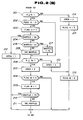
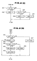
- a series of processings executed in a main routine shown in Figs. 2 (A) to 2 (E) are a regular time interrupt routine driven for each predetermined period (for example, 20 msec.).
- a series of processings executed in a subroutine shown in Fig. 3 is an OCI (Output Compare Interrupt) interrupt routine whose execution start time is determined by the constant time interrupt and driven properly in the main routine according to the signal output period to the stepping motor 12.
- OCI Output Compare Interrupt
- Fig. 2 (A) when an engine key of the vehicle is inserted into a key hole and an ignition switch is turned on, a power supply of the microcomputer is turned on so that the regular time interrupt routine shown in Figs. 2 (A) to 2 (E) is started from a step 100. Then, in the step 101, the control unit 7 determines whether this is a first flow after the power supply is turned on. If this is the first time to execute this routine, a start signal is issued to initialize the control unit 7 such as clearing of the RAM 21. It is noted that if this is not the first flow, the initialization processing is omitted and the routine immediately goes to a step 103.
- the control unit 7 reads a rotation speed V R of the propeller shaft ( rotational speed of the left and right drive wheels) detected by means of the propeller shaft rotation sensor 20, a rotation speed V FR detected by the right driven wheel rotation sensor 17, and the rotation speed V FL detected by the left driven wheel rotation sensor 18.
- a step 104 the control unit 7 calculates a rotation speed V F of the driven wheels 13, 14 from the values of V FR and V FL read in the step 103 as follows:
- control unit calculates the rotation speed V F as an average value of both rotational speeds V FR and V FL .
- the average value V F of both rotation speeds V FR and V FL of the driven wheels 13, 14 coincides with a vehicle body speed.
- a rate of change of the rotation speed VR is calculated from the present rotation speed V R and the rotation speed V( R - 1 ) one previous control cycle in the following way.
- a step 107 the control unit 7 determines whether the VR is equal to or more than zero (V R ⁇ ⁇ 0). If V R is equal to or more than zero (V 0 0 the routine goes to a step 201 of Fig. 2 (B). If V R ⁇ is less than zero (V R ⁇ ⁇ 0) in the step 107, the routine goes to a step 301 of Fig. 2 (C).
- twenty kinds of opening angle characteristic maps are prepared. The numbers of pages are allocated to the twenty kinds of the opening angle characteristic graphs in such a sequence of the wider opening angle of the second throttle valve 3 as page 0, page 1 , page 2, page 3, ---, page 18, and page 19.
- the number of page of the opening angle characteristic maps corresponds to an indicated value of an opening angle characteristic map flag MAPFLG.
- a normal mapping page increment (in this example, one page) is carried out in a step 205.
- the map page increment processing is a processing in which 1 is added to the map flag MAPFLG, i.e., the opening angle characteristic map is selected to be one whose number of pages is such that one is added to the original number of pages.
- the control unit 7 defines a slippage area AREA as 2 and carries out the map page increment processing in steps subsequent to the step 208.
- the slippage area AREA 2 denotes an enclosed region in which the rate of change in the rotation speed V R ⁇ of the drive wheels 15, 16 is equal to or more than zero (V R ⁇ ⁇ 0) and S is equal to or more than S 2 (S ⁇ S 2 ).
- steps 208, 209, 210, and 211 the same series of processings are carried out as in the steps 202, 203, 204, and 205 for a flag B. That is to say, in a case where the slippage S is increased from a value lower than S 2 and thereafter exceeds S 2 , the map page increment processing is once carried out.
- step 303 the routine goes to a step 304 in which the slippage area AREA is defined as 1 in which V R ⁇ ⁇ 0 and S 4 ⁇ S ⁇ S 3 . If S ⁇ S 4 , the routine goes to a step 305 in which the slippage area AREA is defined as 0 in which V R ⁇ 0 and S ⁇ S 4 . Then, the routine goes to a step 401 in the same way as in the step 304.
- Fig. 5 shows a characteristic graph of relationships between the set values Si, S 2 , S 3 , and S 4 of the slippages, slippage areas AREA 0, AREA 1, and AREA 2, and rotation speeds V R and V F .
- the values of S 1 to S 4 indicate inversed hysterisis characteristics such that with the response delay of the engine taken into account the detection speed of the slip is increased and its compensation speed is increased.
- the routine goes to a step 406 in which a map page decrement processing is not carried out but the up timer is incremented by one (Inc. UP TMR) and goes to the step 501.
- the control unit 7 determines whether the slippage area AREA is 2. If the area AREA is 2, i.e., the vehicle runs under a large slip occurrence condition, the routine goes to a step 507 in which a target value STEP" of the opening angle of the second throttle valve 3 is not dependent on the opening angle characteristic map flag MAPFLG but selected from a predetermined value TH A (for example, a value corresponding to an opening angle 5 % of the throttle valve 3). Then, the routine goes to a step 504.
- the control unit 7 reads an opening angle (ASTAGL) of the first throttle valve 2 in a step 502. Then, the control unit 7 in a step 503 searches for the target opening angle of the second throttle valve 3 from the read opening angle ASTAGL of the first throttle valve 2 on the basis of the opening angle characteristic map corresponding to the map flag MAPFLG so as to determine the target opening angle value STEP".
- control unit 7 determines a motor speed on the basis of the difference Oil in steps 505 and 506, determines the normal directional rotation, reverse directional rotation, and holding, sets a period of OCI interrupt, and carries out a flag set indicating the motor direction, etc..
- Fig. 3 shows the OCI interrupt routine.
- a step 800 the control unit 7 determines whether the condition of the stepping motor 12 should be held or should be rotated in the normal/reverse direction. At this time, in a case where the normal direction rotation is determined, 1 is added to the actual opening angle value STEP in a step 801. If the reverse direction rotation is determined, 1 is subtracted from the actual opening angle value STEP of the second throttle valve 3. If holding is determined, the actual opening angle value STEP remains the same.
- a step 803 the motor rotation signal corresponding to 1 STEP in response to a command in the step 800 is outputted to the motor drive circuit 10 so that the stepping motor 12 is driven. Therefore, in a step 803, the motor rotation signal corresponding to 1 STEP is outputted to the motor drive circuit 10 in response to the command in the step 800 so as to drive the motor 12.
- the second throttle valve 3 within the intake air passage 1 shown in Fig. 1 is rotated through an angle corresponding to 1 STEP.
- the OCI interrupt routine shown in Fig. 3 is repeated so that the second throttle valve 3 is pivoted through the target angle.
- Fig. 4 shows one example of the opening angle characteristic maps determining the relationships between the acceleration stroke angle ASTAGL of the first throttle valve 2 and opening angle of the second throttle valve 3 ( in percentage in Fig. 4).
- pages 0 to 19 correspond to map flags MAPFLGs, each flag corresponding to one of the page numbers from 0 to 19 of the opening angle characteristic maps.
- the map of page 0 is an opening angle characteristic map not dependent on the opening angle ASTAGL of the first throttle valve 2 but setting the opening angle of the second throttle valve 3 as a fully open angular position.
- the map of page 19 is not dependent on the opening angle ASTAGL of the first throttle valve 2 but sets the opening angle ASTAGL of the second throttle valve 3 as 5 %.
- the opening angle of the second throttle valve 3 is increased according to the opening angle ASTAGL of the first throttle valve 2.
- the opening angle ASTAGL of the first throttle valve 2 exceeds this threshold value, the opening angle of the second threshold valve 3 is held constant ( not dependent on the opening angle ASTAGL of the first throttle valve 2).
- the map page indicates in an order from 0 to 19, i.e., the map flag MAPFLG becomes greater, the thresold value becomes smaller.
- the thresold value is set so that the opening angle ASTAGL of the second throttle valve 3 becomes smaller with respect to the opening angle ASTAGL of the first throttle valve 2 as shown in Fig. 4.
- the routine advances from the step 201 via the step 202 to the step 203.
- the control unit 7 determines whether the map flag MAPFLG is 19. When the map flag MAPFLG is determined to be 19, the map page increment or decrement is not carried out. If the map flag MAPFLG is not 19, the control unit 7 determines whether the map flag MAPFLG is zero in the step 218. If the map flag MAPFLG is zero, the map page increment is carried out with the map flag MAPFLG 13.
- the routine goes from the step 217 to the step 206.
- the map flag MAPFLG is not zero, the normal map increment is carried out and the routine goes to a step 206.
- the routine goes from the step 213 to the step 401 via the step 216.
- the control unit 7 determines that the vehicle is under the slip condition and carries out no map page decrement.
- the routine advances from the step 407 to the step 501 and the same processing is carried out.
- the routine advances from the step 202 directly to step 206.
- the map page increment is not carried out.
- the routine advances in the following route: steps 301 - 303 - 305 - 401. Thereafter, the routine advances the step 501 in a case where the map flag MAPFLG is zero in the step 402. If not zero, the control unit 7 compares the value of the upper timer UP TMR with the set value T A corresponding to the map increment interval time. If both values do not coincide with each other, the routine goes from the step 406 to the steps 501 - 503 - 504 - 505 - 506.
- Fig. 6 shows characteristic graphs of the tire wheel speed, the opening angle of the second throttle valve 3, and the change in the numbers of pages allocated to the opening angle characteristic maps as compared with the drive wheel speed V R and the change in the slippage S.
- the opening angle characteristic maps such that the opening angle of the second throttle valve 3 is determined by the stroke amount of the accelerator pedal 4 or the opening angle of the first throttle valve 2 are previously stored into the RAM 21, with the rotation speeds of the drive wheels 15, 16 and the driven wheels 13, 14 as parameters, the slippage S is calculated between the drive wheels 15, 16 and road surface. If the slippage S exceeds the preset slip values or are below the preset values, the opening angle of the second throttle valve 3 is stepwise controlled.
- the stepping motor 12 may be replaced with a DC motor or servo motor.
- the system according to the present invention may be used together with other systems such as an ignition timing controlling system, fuel injection rate controlling system, and/or brake controlling system.
- the spring 22 Since the spring 22 is installed on the second throttle valve 3 as described above, the spring 22 serves as a fail safe structure for holding the second throttle valve 3 in the fully open position even though the control circuit 7 or stepping motor 12 fails, thereby the normal running state through the first throttle valve 2 being maintained.
- the driving force controlling system does not only control the opening angle of the second throttle valve merely according to the slip occurrence but also carries out the driving force control such that the opening angle of the second throttle valve is reduced or increased with the opening angle characteristic maps transferred to either of the directions when the slippage exceeds the preset values or is below the present value.
- the rotation of the drive wheels is controlled according to the opening angle of the second throttle valve so as to avoid the occurrence of slip.
- the second throttle valve is stepwise returned to the original state. Therefore, the occurrence of the slip does not again occur.
Landscapes
- Engineering & Computer Science (AREA)
- Chemical & Material Sciences (AREA)
- Combustion & Propulsion (AREA)
- Transportation (AREA)
- Mechanical Engineering (AREA)
- Control Of Vehicle Engines Or Engines For Specific Uses (AREA)
- Control Of Driving Devices And Active Controlling Of Vehicle (AREA)
- Regulating Braking Force (AREA)
- Control Of Throttle Valves Provided In The Intake System Or In The Exhaust System (AREA)
- Electrical Control Of Air Or Fuel Supplied To Internal-Combustion Engine (AREA)
Claims (13)
caractérisé en ce que ledit troisième moyen (7) est conçu pour calculer un patinage ou glissement (S) indiquant ledit glissement de véhicule sur la base desdites première et deuxième vitesses (VR, VF),
le système comprend en outre :
caractérisé par les étapes ultérieures consistant à :
Applications Claiming Priority (2)
| Application Number | Priority Date | Filing Date | Title |
|---|---|---|---|
| JP62324525A JPH0799097B2 (ja) | 1987-12-22 | 1987-12-22 | 車両用駆動力制御装置 |
| JP324525/87 | 1987-12-22 |
Publications (3)
| Publication Number | Publication Date |
|---|---|
| EP0321931A2 EP0321931A2 (fr) | 1989-06-28 |
| EP0321931A3 EP0321931A3 (en) | 1990-05-16 |
| EP0321931B1 true EP0321931B1 (fr) | 1993-10-06 |
Family
ID=18166773
Family Applications (1)
| Application Number | Title | Priority Date | Filing Date |
|---|---|---|---|
| EP88121324A Expired - Lifetime EP0321931B1 (fr) | 1987-12-22 | 1988-12-20 | Système et méthode pour commander la rotation de la roue motrice pour véhicules |
Country Status (4)
| Country | Link |
|---|---|
| US (1) | US4969102A (fr) |
| EP (1) | EP0321931B1 (fr) |
| JP (1) | JPH0799097B2 (fr) |
| DE (1) | DE3884774T2 (fr) |
Families Citing this family (24)
| Publication number | Priority date | Publication date | Assignee | Title |
|---|---|---|---|---|
| US4985837A (en) * | 1988-07-27 | 1991-01-15 | Mitsubishi Jidosha Kogyo Kabushiki Kaisha | Traction control apparatus |
| US5042436A (en) * | 1989-04-19 | 1991-08-27 | Honda Giken Kogyo Kabushiki Kaisha | Valve control system for internal combustion engines |
| US5046461A (en) * | 1989-04-19 | 1991-09-10 | Honda Giken Kogyo Kabushiki Kaisha | Valve control system for internal combustion engines |
| JP3057691B2 (ja) * | 1989-07-19 | 2000-07-04 | トヨタ自動車株式会社 | 車輌の加速スリップ制御装置 |
| US5096016A (en) * | 1989-07-19 | 1992-03-17 | Toyota Jidosha Kabushiki Kaisha | Traction control system for a vehicle with an internal combustion engine |
| DE69031822T2 (de) * | 1989-10-05 | 1998-05-14 | Denso Corp | Saugluftsteuerungssystem für Brennkraftmaschinen |
| JPH03189338A (ja) * | 1989-12-19 | 1991-08-19 | Japan Electron Control Syst Co Ltd | トラクションコントロール装置 |
| JPH03294631A (ja) * | 1990-04-09 | 1991-12-25 | Japan Electron Control Syst Co Ltd | 内燃機関の吸気装置 |
| DE4120419C2 (de) * | 1990-06-21 | 1995-01-26 | Mazda Motor | Traktionssteuereinrichtung für ein Kraftfahrzeug |
| JP2667595B2 (ja) * | 1991-05-23 | 1997-10-27 | 株式会社デンソー | アンチスキッド制御装置 |
| US5366039A (en) * | 1991-06-26 | 1994-11-22 | Nippondenso Co. Ltd. | Acceleration slip control device for a motor vehicle |
| GB2265994B (en) * | 1992-04-09 | 1995-09-06 | Toyota Motor Co Ltd | Engine control apparatus |
| JP3216235B2 (ja) * | 1992-06-22 | 2001-10-09 | トヨタ自動車株式会社 | 加速スリップ制御装置 |
| JPH06330780A (ja) * | 1993-05-21 | 1994-11-29 | Toyota Motor Corp | 車両用演算装置及び車両用演算方法 |
| JP3448995B2 (ja) * | 1994-12-01 | 2003-09-22 | 日産自動車株式会社 | 車両の駆動力制御装置 |
| US7112160B2 (en) * | 2002-06-19 | 2006-09-26 | Yamaha Hatsudoki Kabushiki Kaisha | Air intake system for engine |
| US7128034B2 (en) | 2002-10-18 | 2006-10-31 | Maclean-Fogg Company | Valve lifter body |
| US7273026B2 (en) | 2002-10-18 | 2007-09-25 | Maclean-Fogg Company | Roller follower body |
| US7028654B2 (en) | 2002-10-18 | 2006-04-18 | The Maclean-Fogg Company | Metering socket |
| US6871622B2 (en) | 2002-10-18 | 2005-03-29 | Maclean-Fogg Company | Leakdown plunger |
| US7191745B2 (en) | 2002-10-18 | 2007-03-20 | Maclean-Fogg Company | Valve operating assembly |
| US10130037B2 (en) | 2014-12-31 | 2018-11-20 | Mean Green Products, LLC | Electric mower apparatus and method of use |
| AU2019359884B2 (en) | 2018-10-17 | 2025-01-02 | Generac Power Systems, Inc. | Deck height control system |
| US11032973B2 (en) | 2019-07-26 | 2021-06-15 | Generac Power Systems, Inc. | Battery-operated electric mower |
Family Cites Families (10)
| Publication number | Priority date | Publication date | Assignee | Title |
|---|---|---|---|---|
| JPS61108040A (ja) * | 1984-10-30 | 1986-05-26 | Toyota Motor Corp | 車輪スリツプ制御装置 |
| JPS61283736A (ja) * | 1985-06-08 | 1986-12-13 | Toyota Motor Corp | 車両スリツプ制御装置 |
| JPS6229461A (ja) * | 1985-08-01 | 1987-02-07 | Toyota Motor Corp | 車両の加速スリツプ制御装置 |
| US4765430A (en) * | 1985-10-24 | 1988-08-23 | Volkswagen Ag | Method and arrangement for propulsion regulation of an automobile |
| JPH0620877B2 (ja) * | 1986-04-23 | 1994-03-23 | トヨタ自動車株式会社 | 車両の加速スリツプ制御方法 |
| US4721176A (en) * | 1986-06-13 | 1988-01-26 | General Motors Corporation | Vehicle traction control system |
| US4866618A (en) * | 1986-07-03 | 1989-09-12 | Nissan Motor Co., Ltd. | Engine control system for automotive vehicle |
| DE3722088A1 (de) * | 1986-07-03 | 1988-01-21 | Nissan Motor | Verfahren zum steuern einer brennkraftmaschine und maschinensteuersystem fuer ein kraftfahrzeug |
| JP2545810B2 (ja) * | 1986-10-27 | 1996-10-23 | トヨタ自動車株式会社 | 車両の加速スリツプ制御装置 |
| JPH0620879B2 (ja) * | 1987-03-10 | 1994-03-23 | トヨタ自動車株式会社 | 車両の加速スリツプ制御装置 |
-
1987
- 1987-12-22 JP JP62324525A patent/JPH0799097B2/ja not_active Expired - Fee Related
-
1988
- 1988-11-21 US US07/274,357 patent/US4969102A/en not_active Expired - Lifetime
- 1988-12-20 DE DE88121324T patent/DE3884774T2/de not_active Expired - Lifetime
- 1988-12-20 EP EP88121324A patent/EP0321931B1/fr not_active Expired - Lifetime
Also Published As
| Publication number | Publication date |
|---|---|
| EP0321931A2 (fr) | 1989-06-28 |
| US4969102A (en) | 1990-11-06 |
| DE3884774D1 (de) | 1993-11-11 |
| DE3884774T2 (de) | 1994-01-27 |
| EP0321931A3 (en) | 1990-05-16 |
| JPH01167429A (ja) | 1989-07-03 |
| JPH0799097B2 (ja) | 1995-10-25 |
Similar Documents
| Publication | Publication Date | Title |
|---|---|---|
| EP0321931B1 (fr) | Système et méthode pour commander la rotation de la roue motrice pour véhicules | |
| EP0186122B1 (fr) | Système pour éviter le patinage d'une roue motrice | |
| US4811808A (en) | Acceleration slip control device for a wheeled vehicle | |
| US7899587B2 (en) | Front and rear wheel drive vehicle | |
| US4953093A (en) | System and method for automatically controlling vehicle speed to desired cruise speed with traction control function | |
| US5058699A (en) | Process and circuit configuration for controlling a tsc-system with brake and motor management | |
| EP0655361A2 (fr) | Système de commande de la force d'entraînement pour véhicule | |
| US5168950A (en) | Regulating system for the regulation of the driving torque of the internal combustion engine of a motor vehicle | |
| EP0444910B1 (fr) | Commande du couple d'un moteur de véhicule | |
| EP0574664B1 (fr) | Dispositif de contrÔle pour transmission automatique | |
| JPS6255267A (ja) | 自動車の走行状態判定装置 | |
| US6208921B1 (en) | Vehicle behavior control system | |
| US5366039A (en) | Acceleration slip control device for a motor vehicle | |
| US4866618A (en) | Engine control system for automotive vehicle | |
| JP2502633B2 (ja) | 車両用駆動力制御装置 | |
| US6427130B1 (en) | Method and device for regulating a quantity of motion representing the movement of a vehicle | |
| US5472061A (en) | Driven wheel torque control system | |
| KR100222151B1 (ko) | 차량용 구동력 제어 장치 | |
| US5119299A (en) | Slip control for automotive vehicle with variable engine speed variation characteristics | |
| US20020056584A1 (en) | Front and rear wheel drive vehicle | |
| EP1522698B1 (fr) | Dispositif de commande d'un moteur à combustion interne | |
| JP2575656B2 (ja) | エンジンの制御装置 | |
| JPH0577662A (ja) | 自動車の走行制御装置 | |
| JPH07108631B2 (ja) | 車両用駆動力制御装置 | |
| JP2528456B2 (ja) | 車両用駆動力制御装置 |
Legal Events
| Date | Code | Title | Description |
|---|---|---|---|
| PUAI | Public reference made under article 153(3) epc to a published international application that has entered the european phase |
Free format text: ORIGINAL CODE: 0009012 |
|
| 17P | Request for examination filed |
Effective date: 19881220 |
|
| AK | Designated contracting states |
Kind code of ref document: A2 Designated state(s): DE GB |
|
| PUAL | Search report despatched |
Free format text: ORIGINAL CODE: 0009013 |
|
| AK | Designated contracting states |
Kind code of ref document: A3 Designated state(s): DE GB |
|
| 17Q | First examination report despatched |
Effective date: 19920626 |
|
| GRAA | (expected) grant |
Free format text: ORIGINAL CODE: 0009210 |
|
| AK | Designated contracting states |
Kind code of ref document: B1 Designated state(s): DE GB |
|
| REF | Corresponds to: |
Ref document number: 3884774 Country of ref document: DE Date of ref document: 19931111 |
|
| PLBE | No opposition filed within time limit |
Free format text: ORIGINAL CODE: 0009261 |
|
| STAA | Information on the status of an ep patent application or granted ep patent |
Free format text: STATUS: NO OPPOSITION FILED WITHIN TIME LIMIT |
|
| 26N | No opposition filed | ||
| REG | Reference to a national code |
Ref country code: GB Ref legal event code: IF02 |
|
| PGFP | Annual fee paid to national office [announced via postgrant information from national office to epo] |
Ref country code: GB Payment date: 20071219 Year of fee payment: 20 |
|
| PGFP | Annual fee paid to national office [announced via postgrant information from national office to epo] |
Ref country code: DE Payment date: 20071213 Year of fee payment: 20 |
|
| REG | Reference to a national code |
Ref country code: GB Ref legal event code: PE20 Expiry date: 20081219 |
|
| PG25 | Lapsed in a contracting state [announced via postgrant information from national office to epo] |
Ref country code: GB Free format text: LAPSE BECAUSE OF EXPIRATION OF PROTECTION Effective date: 20081219 |