EP0574664B1 - Dispositif de contrÔle pour transmission automatique - Google Patents
Dispositif de contrÔle pour transmission automatique Download PDFInfo
- Publication number
- EP0574664B1 EP0574664B1 EP93105867A EP93105867A EP0574664B1 EP 0574664 B1 EP0574664 B1 EP 0574664B1 EP 93105867 A EP93105867 A EP 93105867A EP 93105867 A EP93105867 A EP 93105867A EP 0574664 B1 EP0574664 B1 EP 0574664B1
- Authority
- EP
- European Patent Office
- Prior art keywords
- throttle valve
- valve opening
- opening ratio
- accelerator pedal
- unit
- Prior art date
- Legal status (The legal status is an assumption and is not a legal conclusion. Google has not performed a legal analysis and makes no representation as to the accuracy of the status listed.)
- Expired - Lifetime
Links
Images



Classifications
-
- B—PERFORMING OPERATIONS; TRANSPORTING
- B60—VEHICLES IN GENERAL
- B60W—CONJOINT CONTROL OF VEHICLE SUB-UNITS OF DIFFERENT TYPE OR DIFFERENT FUNCTION; CONTROL SYSTEMS SPECIALLY ADAPTED FOR HYBRID VEHICLES; ROAD VEHICLE DRIVE CONTROL SYSTEMS FOR PURPOSES NOT RELATED TO THE CONTROL OF A PARTICULAR SUB-UNIT
- B60W10/00—Conjoint control of vehicle sub-units of different type or different function
- B60W10/04—Conjoint control of vehicle sub-units of different type or different function including control of propulsion units
- B60W10/06—Conjoint control of vehicle sub-units of different type or different function including control of propulsion units including control of combustion engines
-
- B—PERFORMING OPERATIONS; TRANSPORTING
- B60—VEHICLES IN GENERAL
- B60K—ARRANGEMENT OR MOUNTING OF PROPULSION UNITS OR OF TRANSMISSIONS IN VEHICLES; ARRANGEMENT OR MOUNTING OF PLURAL DIVERSE PRIME-MOVERS IN VEHICLES; AUXILIARY DRIVES FOR VEHICLES; INSTRUMENTATION OR DASHBOARDS FOR VEHICLES; ARRANGEMENTS IN CONNECTION WITH COOLING, AIR INTAKE, GAS EXHAUST OR FUEL SUPPLY OF PROPULSION UNITS IN VEHICLES
- B60K28/00—Safety devices for propulsion-unit control, specially adapted for, or arranged in, vehicles, e.g. preventing fuel supply or ignition in the event of potentially dangerous conditions
- B60K28/10—Safety devices for propulsion-unit control, specially adapted for, or arranged in, vehicles, e.g. preventing fuel supply or ignition in the event of potentially dangerous conditions responsive to conditions relating to the vehicle
- B60K28/16—Safety devices for propulsion-unit control, specially adapted for, or arranged in, vehicles, e.g. preventing fuel supply or ignition in the event of potentially dangerous conditions responsive to conditions relating to the vehicle responsive to, or preventing, spinning or skidding of wheels
- B60K28/165—Safety devices for propulsion-unit control, specially adapted for, or arranged in, vehicles, e.g. preventing fuel supply or ignition in the event of potentially dangerous conditions responsive to conditions relating to the vehicle responsive to, or preventing, spinning or skidding of wheels acting on elements of the vehicle drive train other than the propulsion unit and brakes, e.g. transmission, clutch, differential
-
- B—PERFORMING OPERATIONS; TRANSPORTING
- B60—VEHICLES IN GENERAL
- B60W—CONJOINT CONTROL OF VEHICLE SUB-UNITS OF DIFFERENT TYPE OR DIFFERENT FUNCTION; CONTROL SYSTEMS SPECIALLY ADAPTED FOR HYBRID VEHICLES; ROAD VEHICLE DRIVE CONTROL SYSTEMS FOR PURPOSES NOT RELATED TO THE CONTROL OF A PARTICULAR SUB-UNIT
- B60W10/00—Conjoint control of vehicle sub-units of different type or different function
- B60W10/04—Conjoint control of vehicle sub-units of different type or different function including control of propulsion units
-
- B—PERFORMING OPERATIONS; TRANSPORTING
- B60—VEHICLES IN GENERAL
- B60W—CONJOINT CONTROL OF VEHICLE SUB-UNITS OF DIFFERENT TYPE OR DIFFERENT FUNCTION; CONTROL SYSTEMS SPECIALLY ADAPTED FOR HYBRID VEHICLES; ROAD VEHICLE DRIVE CONTROL SYSTEMS FOR PURPOSES NOT RELATED TO THE CONTROL OF A PARTICULAR SUB-UNIT
- B60W10/00—Conjoint control of vehicle sub-units of different type or different function
- B60W10/10—Conjoint control of vehicle sub-units of different type or different function including control of change-speed gearings
- B60W10/11—Stepped gearings
-
- B—PERFORMING OPERATIONS; TRANSPORTING
- B60—VEHICLES IN GENERAL
- B60W—CONJOINT CONTROL OF VEHICLE SUB-UNITS OF DIFFERENT TYPE OR DIFFERENT FUNCTION; CONTROL SYSTEMS SPECIALLY ADAPTED FOR HYBRID VEHICLES; ROAD VEHICLE DRIVE CONTROL SYSTEMS FOR PURPOSES NOT RELATED TO THE CONTROL OF A PARTICULAR SUB-UNIT
- B60W10/00—Conjoint control of vehicle sub-units of different type or different function
- B60W10/10—Conjoint control of vehicle sub-units of different type or different function including control of change-speed gearings
- B60W10/11—Stepped gearings
- B60W10/115—Stepped gearings with planetary gears
-
- B—PERFORMING OPERATIONS; TRANSPORTING
- B60—VEHICLES IN GENERAL
- B60W—CONJOINT CONTROL OF VEHICLE SUB-UNITS OF DIFFERENT TYPE OR DIFFERENT FUNCTION; CONTROL SYSTEMS SPECIALLY ADAPTED FOR HYBRID VEHICLES; ROAD VEHICLE DRIVE CONTROL SYSTEMS FOR PURPOSES NOT RELATED TO THE CONTROL OF A PARTICULAR SUB-UNIT
- B60W30/00—Purposes of road vehicle drive control systems not related to the control of a particular sub-unit, e.g. of systems using conjoint control of vehicle sub-units
- B60W30/18—Propelling the vehicle
- B60W30/18172—Preventing, or responsive to skidding of wheels
-
- B—PERFORMING OPERATIONS; TRANSPORTING
- B60—VEHICLES IN GENERAL
- B60W—CONJOINT CONTROL OF VEHICLE SUB-UNITS OF DIFFERENT TYPE OR DIFFERENT FUNCTION; CONTROL SYSTEMS SPECIALLY ADAPTED FOR HYBRID VEHICLES; ROAD VEHICLE DRIVE CONTROL SYSTEMS FOR PURPOSES NOT RELATED TO THE CONTROL OF A PARTICULAR SUB-UNIT
- B60W30/00—Purposes of road vehicle drive control systems not related to the control of a particular sub-unit, e.g. of systems using conjoint control of vehicle sub-units
- B60W30/18—Propelling the vehicle
- B60W30/1819—Propulsion control with control means using analogue circuits, relays or mechanical links
-
- F—MECHANICAL ENGINEERING; LIGHTING; HEATING; WEAPONS; BLASTING
- F16—ENGINEERING ELEMENTS AND UNITS; GENERAL MEASURES FOR PRODUCING AND MAINTAINING EFFECTIVE FUNCTIONING OF MACHINES OR INSTALLATIONS; THERMAL INSULATION IN GENERAL
- F16H—GEARING
- F16H59/00—Control inputs to control units of change-speed- or reversing-gearings for conveying rotary motion
- F16H59/14—Inputs being a function of torque or torque demand
- F16H59/24—Inputs being a function of torque or torque demand dependent on the throttle opening
-
- F—MECHANICAL ENGINEERING; LIGHTING; HEATING; WEAPONS; BLASTING
- F16—ENGINEERING ELEMENTS AND UNITS; GENERAL MEASURES FOR PRODUCING AND MAINTAINING EFFECTIVE FUNCTIONING OF MACHINES OR INSTALLATIONS; THERMAL INSULATION IN GENERAL
- F16H—GEARING
- F16H61/00—Control functions within control units of change-speed- or reversing-gearings for conveying rotary motion ; Control of exclusively fluid gearing, friction gearing, gearings with endless flexible members or other particular types of gearing
- F16H61/02—Control functions within control units of change-speed- or reversing-gearings for conveying rotary motion ; Control of exclusively fluid gearing, friction gearing, gearings with endless flexible members or other particular types of gearing characterised by the signals used
- F16H61/0202—Control functions within control units of change-speed- or reversing-gearings for conveying rotary motion ; Control of exclusively fluid gearing, friction gearing, gearings with endless flexible members or other particular types of gearing characterised by the signals used the signals being electric
- F16H61/0204—Control functions within control units of change-speed- or reversing-gearings for conveying rotary motion ; Control of exclusively fluid gearing, friction gearing, gearings with endless flexible members or other particular types of gearing characterised by the signals used the signals being electric for gearshift control, e.g. control functions for performing shifting or generation of shift signal
- F16H61/0213—Control functions within control units of change-speed- or reversing-gearings for conveying rotary motion ; Control of exclusively fluid gearing, friction gearing, gearings with endless flexible members or other particular types of gearing characterised by the signals used the signals being electric for gearshift control, e.g. control functions for performing shifting or generation of shift signal characterised by the method for generating shift signals
-
- B—PERFORMING OPERATIONS; TRANSPORTING
- B60—VEHICLES IN GENERAL
- B60W—CONJOINT CONTROL OF VEHICLE SUB-UNITS OF DIFFERENT TYPE OR DIFFERENT FUNCTION; CONTROL SYSTEMS SPECIALLY ADAPTED FOR HYBRID VEHICLES; ROAD VEHICLE DRIVE CONTROL SYSTEMS FOR PURPOSES NOT RELATED TO THE CONTROL OF A PARTICULAR SUB-UNIT
- B60W2510/00—Input parameters relating to a particular sub-units
- B60W2510/06—Combustion engines, Gas turbines
- B60W2510/0638—Engine speed
-
- B—PERFORMING OPERATIONS; TRANSPORTING
- B60—VEHICLES IN GENERAL
- B60W—CONJOINT CONTROL OF VEHICLE SUB-UNITS OF DIFFERENT TYPE OR DIFFERENT FUNCTION; CONTROL SYSTEMS SPECIALLY ADAPTED FOR HYBRID VEHICLES; ROAD VEHICLE DRIVE CONTROL SYSTEMS FOR PURPOSES NOT RELATED TO THE CONTROL OF A PARTICULAR SUB-UNIT
- B60W2520/00—Input parameters relating to overall vehicle dynamics
- B60W2520/10—Longitudinal speed
-
- B—PERFORMING OPERATIONS; TRANSPORTING
- B60—VEHICLES IN GENERAL
- B60W—CONJOINT CONTROL OF VEHICLE SUB-UNITS OF DIFFERENT TYPE OR DIFFERENT FUNCTION; CONTROL SYSTEMS SPECIALLY ADAPTED FOR HYBRID VEHICLES; ROAD VEHICLE DRIVE CONTROL SYSTEMS FOR PURPOSES NOT RELATED TO THE CONTROL OF A PARTICULAR SUB-UNIT
- B60W2540/00—Input parameters relating to occupants
- B60W2540/10—Accelerator pedal position
-
- F—MECHANICAL ENGINEERING; LIGHTING; HEATING; WEAPONS; BLASTING
- F16—ENGINEERING ELEMENTS AND UNITS; GENERAL MEASURES FOR PRODUCING AND MAINTAINING EFFECTIVE FUNCTIONING OF MACHINES OR INSTALLATIONS; THERMAL INSULATION IN GENERAL
- F16H—GEARING
- F16H59/00—Control inputs to control units of change-speed- or reversing-gearings for conveying rotary motion
- F16H59/50—Inputs being a function of the status of the machine, e.g. position of doors or safety belts
- F16H2059/506—Wheel slip
-
- F—MECHANICAL ENGINEERING; LIGHTING; HEATING; WEAPONS; BLASTING
- F16—ENGINEERING ELEMENTS AND UNITS; GENERAL MEASURES FOR PRODUCING AND MAINTAINING EFFECTIVE FUNCTIONING OF MACHINES OR INSTALLATIONS; THERMAL INSULATION IN GENERAL
- F16H—GEARING
- F16H59/00—Control inputs to control units of change-speed- or reversing-gearings for conveying rotary motion
- F16H59/14—Inputs being a function of torque or torque demand
- F16H59/18—Inputs being a function of torque or torque demand dependent on the position of the accelerator pedal
-
- F—MECHANICAL ENGINEERING; LIGHTING; HEATING; WEAPONS; BLASTING
- F16—ENGINEERING ELEMENTS AND UNITS; GENERAL MEASURES FOR PRODUCING AND MAINTAINING EFFECTIVE FUNCTIONING OF MACHINES OR INSTALLATIONS; THERMAL INSULATION IN GENERAL
- F16H—GEARING
- F16H59/00—Control inputs to control units of change-speed- or reversing-gearings for conveying rotary motion
- F16H59/36—Inputs being a function of speed
- F16H59/44—Inputs being a function of speed dependent on machine speed, e.g. the vehicle speed
Definitions
- the present invention deals with an automatic transmission control system as shown in the closest prior art according to the US-A-5,047,940.
- This known system has a traction control system comprising a throttle valve whose degree of opening is set in response to the actuation of an accelerator pedal and which is adjusted in the closed state if the control system detects a slip at one of the wheels. Furthermore the known automatic transmission control systems offers the possibility of changing the shift point in case the traction control system is activated such that a shifting from a lower to a higher gear is already effected at a speed which is lower than that in the case of an inactive transmission control system.
- the invention has to be seen in that the shift point is changed as claimed in the enclosed claim 1 when the degree of operation of the accelerator pedal is equal to or greater than a predetermined value and when the traction control system is ON.
- the shift point is changed when the degree of operation- of the accelerator pedal is large (equal to or greater than the predetermined value).
- the shift point is not changed if the degree of operation of the accelerator pedal is small.
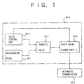
- FIG. 1 illustrates an overview of the present invention.
- An automatic transmission control system that controls an automatic transmission M5 includes an accelerator pedal M1, a throttle valve M2, a valve control unit M3, and a shift point change unit M6.
- M4 denotes an internal combustion engine.
- the shift point change unit M6 changes the shift point towards a low engine speed when the quantity of depression (degree of operation or setting) of the accelerator pedal M1 becomes equal to or greater than a threshold value. Hence, wheel slippage can be prevented when the accelerator pedal M1 is deeply depressed.
- the automatic transmission performs shift control on the basis of the opening ratio of the throttle valve M2 and the vehicle speed. It will now be assumed that the vehicle is traveling on a slippery road (low- ⁇ road) like an iced road while the traction control (TRC) is ON and the throttle valve M2 is maintained in the closed state. When the driver depresses the accelerator pedal M1, the engine speed increases but the driving force is not transferred to the road because of wheel slippage. Hence, the vehicle speed does not increase. Since gear shifting is based on the opening ratio of the throttle valve and the vehicle speed, the engine speed increases to a high value until the vehicle speed reaches the shift point while the vehicle is traveling on the slippery (low- ⁇ ) road.
- TRC traction control
- the shift point change unit M6 changes the shift point towards a low engine speed when the amount of operation of the accelerator pedal M1 becomes equal to or greater than the threshold value.
- the gear shifting occurs before the engine speed reaches a value causing a large amount of wheel slippage.
- wheel slippage because of gear shifting, particularly when the vehicle is traveling on a slippery road, can be prevented, and stable driving can be obtained.
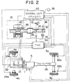
- FIG. 2 illustrates the entire structure of a vehicle equipped with a control system for an automatic transmission.
- An internal combustion engine 10 is mounted on a vehicle 1.
- Driving wheels 3a and 3b are driven by the engine 10 through an automatic transmission 5 and a drive shaft 26.
- the vehicle 1 also has idler wheels 4a and 4b.
- Wheel speed sensors 22a, 22b, 24a and 24b for respectively detecting wheel speeds of the driving wheels 3a and 3b and the idler wheels 4a and 4b are provided for these wheels.
- a main throttle valve 14 responding to a driver's operation of an accelerator pedal 12 is provided in an air intake passage of the internal combustion engine 10.
- a sub-throttle valve 16 is fastened to the intake air passage and located on the upstream side of the main throttle valve 14.
- the sub-throttle valve 16 is driven by a stepping motor 18.
- a control unit 30 includes two integrated digital computers. One of the two digital computers functions as an electronic fuel injection (EFI) unit, and the other digital computer functions as an automatic transmission control (ECT) unit.
- EFI unit performs fuel injection control and ignition timing control.
- the ECT unit performs shifting control of the automatic transmission 5.
- the control unit 30 receives, as the EFI unit, a sensor output signal of an engine speed sensor 32, a sensor output signal of a main throttle valve opening ratio sensor 34, and a sensor output signal of a sub-throttle valve opening ratio sensor 36. Further, the control unit 30 receives desired sensor output signals of other sensors necessary for engine control as in the case of conventional engines.
- the control unit 30 is connected to a fuel injection valve 38 and an igniter 40.
- the control unit 30 controls the quantity of fuel injection and the ignition timing via the fuel injection valve 38 and the igniter 40.
- the control unit 30 controls, as the ECT unit, the shift point most suitable for the current driving conditions on the basis of a sensor output signal of a vehicle speed sensor 35 and data indicating a main throttle valve opening ratio ⁇ MG from the EFI unit.
- the system shown in Fig. 2 includes an acceleration slip control unit (traction control unit: TRC unit) 50.
- the TRC unit 50 is formed with a digital computer, and is supplied with the sensor output signal of the engine speed sensor 32 and the sensor output signals of the main and sub-throttle valve opening ratio sensors 34 and 36 in order to perform the traction control. Further, the TRC unit 50 controls the opening ratio of the sub-throttle valve 16. Furthermore, the TRC unit 50 is connected to the control unit 30, and outputs a signal FS, a fuel cut signal and an ignition timing delay angle signal to the control unit 30. The FS signal indicates whether or not the TRC is being performed.
- the present embodiment carries out driving torque control by controlling the opening ratio of the sub-throttle valve 16 on the basis of slippage of the driving wheels 3a and 3b.
- K 1 , K 2 and K 3 are respectively positive constants, and ⁇ V is the difference between a target driving wheel speed V S obtained from a vehicle speed (idler wheel speed) V B , and the actual driving wheel speed V D .
- the slip quantity ⁇ V is defined as V S - V D .
- ⁇ G is the difference between the ratio of variation of the vehicle speed V R and the rate of variation of the driving wheel speed V D , that is,
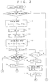
- Figs. 3 and 4 show a basic routine of the traction control performed by the TRC unit 50.
- the basic routine is repeatedly executed with a repetition period of, for example, 12msec.
- the TRC unit 50 determines whether or not a TRC execution condition is satisfied.
- the main throttle valve is not completely closed and the sensors operate normally when the TRC execution condition is satisfied.
- step 100 When it is determined, in step 100, that the TRC execution condition is not satisfied, the TRC unit 50 executes step 154, in which step all flags are reset and ⁇ smax (full throttle) is set as the sub-throttle valve opening ratio ⁇ s . Then, the TRC unit 50 ends execution of the routine.
- step 104 the TRC unit 50 calculates the target driving wheel speed V S in the following manner:
- step 106 the TRC unit 50 sets a control starting speed V TB of the traction control.
- step 112 When it is determined, in step 112 that the driving wheel speed V D is higher than the control starting speed V TB , the TRC unit 50 sets the flag FS to 1 in step 114. Then, the TRC unit 50 sets the subthrottle valve opening ratio ⁇ s to an initial target opening ratio f (NE) in step 116, and resets the flag FFBS to zero in step 118, the flag FFBS being an initial feedback control inhibit flag. Then, the TRC unit 50 ends execution of the routine.
- NE initial target opening ratio
- the initial target opening ratio f (NE) of the sub-throttle valve 16 is selected on the basis of the engine speed NE and the road surface conditions.
- the sub-throttle valve 16 is maintained in the full-throttle state when the traction control is not performed.
- feedback control is started in the full-throttle state of the sub-throttle valve 16
- the sub-throttle valve 16 is closed up to an opening ratio ( ⁇ s ) at which a response appears, at the same time as the traction control is started, and then the feedback control is started.
- the initial feedback control inhibit flag FFBS is set to 1 when a predetermined requirement is satisfied after the traction control is started.
- step 132 step it is determined, on the basis of the signal from the sub-throttle valve opening ratio sensor 36, whether or not the sub-throttle valve 16 has been closed to the initial target opening ratio ⁇ s .
- the TRC 50 ends execution of the routine.
- step 134 the TRC unit 50 executes step 134 in which step a feedback control inhibit flag FFBI is set to 1.
- step 136 (Fig. 4) the TRC unit 50 determines whether or not the feedback inhibit flag FFBI is equal to 1.
- the TRC unit 50 ends execution of the routine.
- the feedback inhibit flag FFBI is a flag set in a shift-up control performed by the ECT unit of the control unit 30. More particularly, the feedback inhibit flag FFBI is set to 1 at the time of shift control by the ECT unit.
- the ECT unit performs the shift-up control by the step-136 process, execution of the basic control routine (feedback control after step 140) with respect to the sub-throttle valve 16 is inhibited.
- step 138 the TRC unit 50 determines whether or not the initial feedback control inhibit flag FFBS is equal to 1.
- the feedback control from step 140 controls the sub-throttle valve opening ratio ⁇ s .
- the TRC unit 0 ends execution of the routine without executing steps 140 - 154.
- step 140 the TRC unit 50 executes step 140 from which step the feedback control of the sub-throttle valve opening ratio ⁇ s is started.
- step 138 the TRC unit 50 determines a control quantity ⁇ s with respect to the sub-throttle opening ratio.
- the traction control is continued while a condition remains satisfied and as long as a predetermined time has not elapsed.
- the above condition is such that the sub-throttle valve opening ratio ⁇ s is greater than the main throttle valve opening ratio ⁇ M (step 144), and the absolute value of the slip quantity
- the above-mentioned predetermined time is measured by using a parameter CEND, which is incremented by 1 in step 148.
- the TRC unit 50 determines whether or not the value of the parameter CEND is greater than D where D is the above-mentioned predetermined time.
- step 150 When it is determined, in step 150, that the traction control should be terminated (when the result of step 150 is affirmative), the flags FS, FFBS and CEND are reset to zero, and the sub-throttle valve opening ratio ⁇ s is set to ⁇ smax (full-throttle state) in step 154.
- the control unit 30 is informed of the value of the flag FS set in step 114 (Fig. 3).
- the EFI unit of the control unit 30 is supplied with information indicating the engine speed NE, the main throttle valve opening ratio ⁇ M , and the sub-throttle valve opening ratio ⁇ s and other sensor signals necessary for engine control.
- the control unit 30 performs the fuel injection control and the ignition timing control using the above information and sensor signals.
- the ECT unit of the control unit 30 controls the shift point most suitable for the current driving conditions on the basis of the vehicle speed SPD indicated by the vehicle sensor 35 and a coded stepwise main throttle valve opening ratio ⁇ MG .
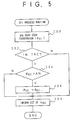
- the process shown in Fig. 5 is carried out in synchronism with the basic control routine of the traction control shown in Figs. 3 and 4 with a period of 12msec.
- step 200 the control unit 30 obtains the main throttle valve opening ratio ⁇ M from the output signal of the main throttle valve opening ratio sensor 34, and carries out a Gray code conversion operation on the valve opening ratio ⁇ M , so that the coded main throttle valve opening ratio ⁇ MG can be obtained.
- the main throttle valve opening ratio (0% - 100%) is converted into one of nine steps between ⁇ 0 (0%) and ⁇ 8 (100%).
- the control unit 30 determines, in step 202, whether or not the traction control is being performed. This determination is performed by referring to the traction control execution flag FS (step 114 shown in Fig. 3) controlled by the TRC unit 50. When it is determined, in step 202, that the traction control is not being performed, the EFI unit of the control unit 30 executes step 208 and informs the ECT unit thereof of the coded main throttle valve opening ratio ⁇ MG calculated in step 200.
- step 202 When it is determined, in step 202, that the traction control is not being performed, the EFI unit of the control unit 30 executes step 208 in which step the ECT unit of the control unit 30 is informed of the main throttle valve opening ratio ⁇ MG .
- step 204 When it is determined, in step 204, that the current main throttle valve opening ratio ⁇ MG is equal to a valve opening ratio at which slip because of gear shifting may occur, in other words, it is determined that ⁇ MG is an upper guard value A%, the control unit 30 executes step 206 in which step a main throttle valve opening ratio ⁇ MG-1 lower than the actual main throttle valve opening ratio ⁇ MG by one step is determined as the current main throttle valve opening ratio ⁇ MG .
- step 206 the main throttle valve opening ratio ⁇ 6 lower than the main throttle valve opening ratio ⁇ 7 by one step is set as the main throttle valve opening ratio ⁇ MG .
- step 208 the ECT unit is informed of the main throttle valve opening ratio ⁇ MG determined in the above manner.
- step 204 When the result of step 204 is negative, that is, when it is determined that the current main throttle valve opening ratio ⁇ MG does not cause wheel slippage due to gear shifting, the steps 204 and 206 are not executed, and the ECT unit is informed of the read main throttle valve opening ratio ⁇ MG .
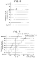
- Fig. 7 shows up-shifting as a function of the throttle valve opening ratio and the vehicle speed.
- the ECT unit of the control unit 30 performs the gear shifting process on the basis of the diagram of Fig. 7.
- Fig. 8 is a flowchart of the gear shifting process performed by the ECT unit 30. The flowchart of Fig. 8 relates to a case where the gear is shifted from the first gear to the second rear.
- the ECT unit of the control unit 30 is informed of the main throttle valve opening ratio ⁇ MG sent from the EFI thereof in step 300.
- the main throttle valve opening ratio ⁇ MG input in step 300 is equal to the main throttle valve opening ratio lower than the actual main throttle valve opening ratio by one step when the actual main throttle valve opening ratio is higher than the upper guard value A%.
- the main throttle valve opening ratio ⁇ MG input in step 300 is equal to the actual main throttle valve opening ratio when it is not higher than the upper guard value A%.
- the main throttle valve opening ratio ⁇ MG input in step 300 is equal to ⁇ 7 , which is higher than the upper guard value A%. Hence, by the process of steps 204 and 206, the main throttle valve opening ratio ⁇ MG is set equal to ⁇ 6 .
- step 302 the ECT unit of the control unit 30 determines whether or not the vehicle speed SPD indicated by the sensor output signal of the speed sensor 35 is equal to or greater than a threshold vehicle speed V 1 .
- the ECT unit executes step 304 in which step it is determined that the current gear shift position is at the first gear.
- step 306 the ECT unit performs the up-shifting process from the first gear to the second gear.
- the ECT unit performs the gear shifting process on the basis of the main throttle valve opening ratio ⁇ MG sent from the EFI. More particularly, in the setting process of the main throttle valve opening ratio ⁇ MG by the EFI unit, when the actual main throttle valve opening ratio ⁇ MG is higher than the upper guard value A%, data indicating the main throttle valve opening ratio ⁇ MG-1 lower than the actual one by one step is sent to the ECT unit.
- up-shifting is made at an engine speed which is lower than the conventional engine speed (corresponding to V 2 ) by an engine speed corresponding to the difference between the vehicle speeds V1 and V2.
- the above up-shifting process is equivalent to a process in which the shifting point is changed towards the low-engine-speed side.
- the shift point of the up-shifting process is changed to the low-engine-speed side when the degree of depression of the accelerator pedal 12 is equal to or greater than the threshold value and the main throttle valve opening ratio ⁇ MG is higher than the upper guard value A%.
- the engine speed can be reduced when up-shifting is made, and the unstable behavior of the vehicle due to gear shifting performed when the vehicle is traveling on a slippery (low- ⁇ ) road can be effectively prevented.
- step 206 shown in Fig. 5 the main throttle valve opening ratio ⁇ MG-1 lower than the actual main throttle valve opening ratio ⁇ MG by one step is used instead of the valve opening ratio ⁇ MG when the actual valve opening ratio ⁇ MG exceeds the upper guard value A%.
- the actual main throttle valve opening ratio ⁇ MG is ⁇ 8
- ⁇ 7 is used instead of ⁇ 8
- ⁇ 6 is used instead of ⁇ 7 .
- step 206A shown in Fig. 9 instead of step 206 shown in Fig. 5.
- step 206A when the actual main throttle valve opening ratio ⁇ MG exceeds the upper guard value A%, the main throttle valve opening ratio to be used is set to a predetermined constant ratio ⁇ TH without exception.
- the predetermined constant ratio ⁇ TH By using the predetermined constant ratio ⁇ TH , the occurrence of wheel slippage can be effectively prevented, particularly when the degree of depression of the accelerator pedal 12 is great.
- the constant upper guard value A% is used.
- the shift point is changed to a shift point lower than the normal shift point during execution of the traction control.
- a first shift point map to be used when the traction control is OFF and a second shift point map to be used when the traction control is ON and to select either the first shift point map or the second shift point map.
- the wheel speed sensors 22a and 22b are provided for the driving wheels 3a and 3b, respectively.
- a single revolution speed sensor for detecting the revolution of the drive shaft 26.
- the engine 10 is equipped with the main throttle valve 14 and the sub-throttle valve 16.
- the present invention can be applied to an engine in which the traction control is performed using a single throttle valve provided for the engine.
- the quantity of depression of the accelerator pedal 12 is used as the main throttle opening ratio
- the main throttle valve opening ratio is used as the sub-throttle valve opening ratio.
Landscapes
- Engineering & Computer Science (AREA)
- Chemical & Material Sciences (AREA)
- Combustion & Propulsion (AREA)
- Mechanical Engineering (AREA)
- Transportation (AREA)
- General Engineering & Computer Science (AREA)
- Automation & Control Theory (AREA)
- Control Of Transmission Device (AREA)
- Control Of Vehicle Engines Or Engines For Specific Uses (AREA)
- Control Of Driving Devices And Active Controlling Of Vehicle (AREA)
Claims (4)
- Dispositif de contrôle pour la transmission automatique fourni pour un moteur à combustion interne (M4) ayant un dispositif de transmission automatique équipé d'un dispositif de contrôle de traction dans lequel une valve d'étranglement (M2) est ajustée vers un état fermé à partir d'une position d'étranglement correspondant à l'opération d'une pédale d'accélérateur (M1) lorsque un patinage des roues survient, ledit système de contrôle pour la transmission automatique comprenant :un moyen de détection (M6) pour détecter un degré de fonctionnement de la pédale d'accélérateur, etun moyen de changement du point d'embrayage (M6) couplé audit moyen de détection de manière à ce que le changement de vitesse survienne sur la base du degré de fonctionnement de la pédale d'accélérateur (12) dans un état normal et le changement de vitesse survient à une vitesse du moteur plus basse qu'une vitesse de moteur prédéterminée à laquelle le changement de vitesse survient normalement lorsque le degré de fonctionnement de la pédale d'accélérateur est supérieur ou égal à une valeur prédéterminée dans laquelle des premiers moyens sont fournis pour déterminer si oui ou non le contrôle de traction est ON et des seconds moyens sont fournis pour permettre au moyen de changement de point d'embrayage de changer le point d'embrayage lorsque le premier moyen conclut que le contrôle de traction est ON.
- Système de contrôle pour la transmission automatique selon la revendication 1,
caractérisé en ce que :
ledit moyen de changement de point d'embrayage (M6) comporte un premier moyen pour le changement du point d'embrayage sur la base d'un degré de fonctionnement de la pédale d'accélérateur (M1) plus petit que le degré de fonctionnement qui est réellement détecté lorsque le degré de fonctionnement de la pédale d'accélérateur (M1) est supérieur ou égal à la valeur prédéterminée. - Système de contrôle pour la transmission automatique selon la revendication 1,
caractérisé en ce :
il comporte en outre :- une première valve d'étranglement (14) coopérant avec la pédale d'accélérateur (Ml);- une seconde valve d'étranglement (16); et- un moyen d'entraînement (18) pour entraîner la seconde valve d'étranglement (16) lorsqu'un patinage de roue survient, eten ce que :
ledit moyen de détection comporte un premier moyen (34) pour détecter le taux d'ouverture de la valve d'étranglement de la première valve d'étranglement (14) comme le degré de fonctionnement de la pédale d'accélérateur (M1). - Dispositif de contrôle pour la transmission automatique selon la revendication 3,
caractérisé en ce que :
ledit moyen de changement du point d'embrayage (M6) comporte :- un second moyen pour convertir le taux d'ouverture de la valve d'étranglement détecté par ledit premier moyen (34) dans l'un des rapports d'ouverture de la valve d'étranglement prédéterminée par palier; et- un troisième moyen pour sélectionner l'un des taux d'ouverture de la valve d'étranglement prédéterminée par palier qui est un pas plus bas que celui des taux d'ouverture de la valve d'étranglement prédéterminée par palier qui correspond au taux d'ouverture de la valve d'étranglement détecté par ledit premier moyen (34).
Applications Claiming Priority (2)
| Application Number | Priority Date | Filing Date | Title |
|---|---|---|---|
| JP4155298A JP2950022B2 (ja) | 1992-06-15 | 1992-06-15 | 自動変速機の制御装置 |
| JP155298/92 | 1992-06-15 |
Publications (2)
| Publication Number | Publication Date |
|---|---|
| EP0574664A1 EP0574664A1 (fr) | 1993-12-22 |
| EP0574664B1 true EP0574664B1 (fr) | 1996-11-06 |
Family
ID=15602842
Family Applications (1)
| Application Number | Title | Priority Date | Filing Date |
|---|---|---|---|
| EP93105867A Expired - Lifetime EP0574664B1 (fr) | 1992-06-15 | 1993-04-08 | Dispositif de contrÔle pour transmission automatique |
Country Status (8)
| Country | Link |
|---|---|
| US (1) | US5405301A (fr) |
| EP (1) | EP0574664B1 (fr) |
| JP (1) | JP2950022B2 (fr) |
| KR (1) | KR950014664B1 (fr) |
| CA (1) | CA2093690C (fr) |
| DE (1) | DE69305790T2 (fr) |
| ES (1) | ES2094957T3 (fr) |
| TW (1) | TW325446B (fr) |
Families Citing this family (20)
| Publication number | Priority date | Publication date | Assignee | Title |
|---|---|---|---|---|
| JPH0874987A (ja) * | 1994-09-01 | 1996-03-19 | Toyota Motor Corp | 自動変速機付車両のスリップ検出装置 |
| JP3727373B2 (ja) * | 1995-03-03 | 2005-12-14 | 三菱電機株式会社 | 自動変速機の変速制御装置 |
| US5628378A (en) * | 1995-03-10 | 1997-05-13 | Honda Giken Kogyo Kabushiki Kaisha | Traction control device for vehicle |
| JPH094705A (ja) * | 1995-06-16 | 1997-01-07 | Aisin Aw Co Ltd | 自動変速機の制御装置 |
| JPH094485A (ja) * | 1995-06-19 | 1997-01-07 | Nissan Motor Co Ltd | 車両用駆動力制御装置 |
| JP3209065B2 (ja) * | 1995-12-14 | 2001-09-17 | 日産自動車株式会社 | 自動変速機の変速制御方法 |
| EP0784001B1 (fr) * | 1996-01-12 | 2002-07-31 | Eaton Corporation | Système/méthode de commande de changement de vitesses pour véhicule équipé d'un ralentisseur de ligne de transmission |
| JPH1038067A (ja) * | 1996-07-18 | 1998-02-13 | Toyota Motor Corp | 車両の制御装置 |
| JPH10110817A (ja) * | 1996-10-04 | 1998-04-28 | Toyota Motor Corp | 車両の制御装置 |
| JP3099187B2 (ja) * | 1997-08-22 | 2000-10-16 | 本田技研工業株式会社 | 車両用自動変速機の制御装置 |
| US6577944B1 (en) | 1999-02-19 | 2003-06-10 | Shannon R. Davis | Traction control system |
| WO2000048860A1 (fr) * | 1999-02-19 | 2000-08-24 | Davis Shanon R | Systeme de regulation de traction |
| JP2001065383A (ja) * | 1999-08-06 | 2001-03-13 | Robert Bosch Gmbh | 駆動滑り制御システム |
| JP2002322923A (ja) * | 2001-04-26 | 2002-11-08 | Jatco Ltd | 車両のトラクションコントロール装置 |
| JP4810760B2 (ja) * | 2001-06-12 | 2011-11-09 | アイシン精機株式会社 | 自動変速機の制御装置 |
| JP4040492B2 (ja) * | 2003-02-24 | 2008-01-30 | 株式会社クボタ | 作業車の走行操作装置 |
| JP4743057B2 (ja) * | 2006-09-12 | 2011-08-10 | トヨタ自動車株式会社 | 内燃機関のスロットル開度制御装置 |
| SE534961C2 (sv) * | 2009-09-14 | 2012-02-28 | Scania Cv Ab | System för styrning av växlingspunkter |
| US8554440B1 (en) | 2010-01-05 | 2013-10-08 | Davis Intellectual Properties LLC | Electronic traction control |
| US8755986B2 (en) * | 2010-09-09 | 2014-06-17 | GM Global Technology Operations LLC | Vehicle acceleration when in an air restriction mode |
Family Cites Families (10)
| Publication number | Priority date | Publication date | Assignee | Title |
|---|---|---|---|---|
| JPS5838347A (ja) * | 1981-08-31 | 1983-03-05 | Toyota Motor Corp | 車両用エンジン集中制御装置 |
| DE3711913C2 (de) * | 1987-04-08 | 2000-05-31 | Bosch Gmbh Robert | Verfahren und Vorrichtung zur Antriebsschlupfverhinderung |
| JPH0623029B2 (ja) * | 1987-07-30 | 1994-03-30 | マツダ株式会社 | 自動変速機を備えた車両のスリップ防止装置 |
| JPH01164850A (ja) * | 1987-12-17 | 1989-06-28 | Daikin Mfg Co Ltd | 自動車用自動変速機の変速制御装置 |
| JPH01218932A (ja) * | 1988-02-26 | 1989-09-01 | Japan Electron Control Syst Co Ltd | 自動変速機の変速制御装置 |
| US5047940A (en) * | 1988-06-07 | 1991-09-10 | Mazda Motor Corporation | Power train control apparatus for a vehicle |
| JPH0257441A (ja) * | 1988-08-20 | 1990-02-27 | Nissan Motor Co Ltd | 自動変速機の変速点制御装置 |
| JPH02279431A (ja) * | 1989-04-20 | 1990-11-15 | Mazda Motor Corp | パワートレイン制御装置および制御方法 |
| JPH0751903B2 (ja) * | 1989-09-05 | 1995-06-05 | 日産自動車株式会社 | 車両用エンジン出力制御装置 |
| JPH04100738A (ja) * | 1990-08-15 | 1992-04-02 | Aisin Aw Co Ltd | 電子制御式自動変速機 |
-
1992
- 1992-06-15 JP JP4155298A patent/JP2950022B2/ja not_active Expired - Fee Related
-
1993
- 1993-04-01 US US08/042,097 patent/US5405301A/en not_active Expired - Lifetime
- 1993-04-08 EP EP93105867A patent/EP0574664B1/fr not_active Expired - Lifetime
- 1993-04-08 CA CA002093690A patent/CA2093690C/fr not_active Expired - Fee Related
- 1993-04-08 DE DE69305790T patent/DE69305790T2/de not_active Expired - Fee Related
- 1993-04-08 ES ES93105867T patent/ES2094957T3/es not_active Expired - Lifetime
- 1993-05-27 TW TW082104201A patent/TW325446B/zh not_active IP Right Cessation
- 1993-06-11 KR KR1019930010589A patent/KR950014664B1/ko not_active Expired - Fee Related
Also Published As
| Publication number | Publication date |
|---|---|
| KR950014664B1 (ko) | 1995-12-13 |
| ES2094957T3 (es) | 1997-02-01 |
| US5405301A (en) | 1995-04-11 |
| JPH05345539A (ja) | 1993-12-27 |
| JP2950022B2 (ja) | 1999-09-20 |
| CA2093690A1 (fr) | 1993-12-16 |
| TW325446B (en) | 1998-01-21 |
| DE69305790D1 (de) | 1996-12-12 |
| KR940000304A (ko) | 1994-01-03 |
| EP0574664A1 (fr) | 1993-12-22 |
| DE69305790T2 (de) | 1997-03-20 |
| CA2093690C (fr) | 1998-07-14 |
Similar Documents
| Publication | Publication Date | Title |
|---|---|---|
| US5405301A (en) | Automatic transmission control system | |
| EP0321931B1 (fr) | Système et méthode pour commander la rotation de la roue motrice pour véhicules | |
| US5813936A (en) | Driving force controller in vehicle for forcibly upshifting in response to a driving force traction controller and a vehicle stopped detection means | |
| US6182002B1 (en) | Vehicle acceleration based traction control | |
| US5067578A (en) | Traction control system for motor vehicles | |
| EP0554892B1 (fr) | Dispositif de commande de traction d'un véhicule automobile équipé d'une transmission automatique | |
| US5722500A (en) | Continuously variable transmission control apparatus | |
| US6334500B1 (en) | Slip control method for traction control system | |
| JP3536523B2 (ja) | 車両用駆動力制御装置 | |
| JP3216235B2 (ja) | 加速スリップ制御装置 | |
| KR102323962B1 (ko) | 저마찰로에서 차량 급가속시 변속 제어 방법 및 시스템 | |
| US6782962B2 (en) | Vehicle traction control system | |
| JP2964770B2 (ja) | 自動変速機の制御装置 | |
| US5038288A (en) | Vehicle driving force controlling method and apparatus therefor | |
| JPH094485A (ja) | 車両用駆動力制御装置 | |
| JPH0730722B2 (ja) | 自動車のスキツド制御装置 | |
| US5180027A (en) | Traction control system for motor vehicles | |
| JP3985450B2 (ja) | 駆動力制御装置 | |
| JPH07108631B2 (ja) | 車両用駆動力制御装置 | |
| EP0349254B1 (fr) | Méthode pour contrôler le patinage des roues motrices d'un véhicule | |
| EP0325290B1 (fr) | Système de commande d'adhérence pour automobiles | |
| JP3575223B2 (ja) | 車両用駆動力制御装置 | |
| JPH068905Y2 (ja) | 自動車のトラクシヨンコントロ−ル装置 | |
| JP2932103B2 (ja) | 路面摩擦係数検出装置とこれを用いたエンジントルク制御装置及び車両の変速制御装置 | |
| JP2578865B2 (ja) | 車両用駆動力制御装置 |
Legal Events
| Date | Code | Title | Description |
|---|---|---|---|
| PUAI | Public reference made under article 153(3) epc to a published international application that has entered the european phase |
Free format text: ORIGINAL CODE: 0009012 |
|
| 17P | Request for examination filed |
Effective date: 19930408 |
|
| AK | Designated contracting states |
Kind code of ref document: A1 Designated state(s): DE ES FR GB IT |
|
| 17Q | First examination report despatched |
Effective date: 19940516 |
|
| GRAG | Despatch of communication of intention to grant |
Free format text: ORIGINAL CODE: EPIDOS AGRA |
|
| GRAH | Despatch of communication of intention to grant a patent |
Free format text: ORIGINAL CODE: EPIDOS IGRA |
|
| GRAH | Despatch of communication of intention to grant a patent |
Free format text: ORIGINAL CODE: EPIDOS IGRA |
|
| GRAA | (expected) grant |
Free format text: ORIGINAL CODE: 0009210 |
|
| AK | Designated contracting states |
Kind code of ref document: B1 Designated state(s): DE ES FR GB IT |
|
| REF | Corresponds to: |
Ref document number: 69305790 Country of ref document: DE Date of ref document: 19961212 |
|
| ET | Fr: translation filed | ||
| REG | Reference to a national code |
Ref country code: ES Ref legal event code: FG2A Ref document number: 2094957 Country of ref document: ES Kind code of ref document: T3 |
|
| ITF | It: translation for a ep patent filed | ||
| PLBE | No opposition filed within time limit |
Free format text: ORIGINAL CODE: 0009261 |
|
| 26N | No opposition filed | ||
| REG | Reference to a national code |
Ref country code: GB Ref legal event code: IF02 |
|
| REG | Reference to a national code |
Ref country code: GB Ref legal event code: 746 Effective date: 20030918 |
|
| REG | Reference to a national code |
Ref country code: FR Ref legal event code: D6 |
|
| PGFP | Annual fee paid to national office [announced via postgrant information from national office to epo] |
Ref country code: ES Payment date: 20090513 Year of fee payment: 17 |
|
| PGFP | Annual fee paid to national office [announced via postgrant information from national office to epo] |
Ref country code: IT Payment date: 20090424 Year of fee payment: 17 Ref country code: FR Payment date: 20090417 Year of fee payment: 17 Ref country code: DE Payment date: 20090402 Year of fee payment: 17 |
|
| PGFP | Annual fee paid to national office [announced via postgrant information from national office to epo] |
Ref country code: GB Payment date: 20090408 Year of fee payment: 17 |
|
| GBPC | Gb: european patent ceased through non-payment of renewal fee |
Effective date: 20100408 |
|
| REG | Reference to a national code |
Ref country code: FR Ref legal event code: ST Effective date: 20101230 |
|
| PG25 | Lapsed in a contracting state [announced via postgrant information from national office to epo] |
Ref country code: FR Free format text: LAPSE BECAUSE OF NON-PAYMENT OF DUE FEES Effective date: 20100430 |
|
| PG25 | Lapsed in a contracting state [announced via postgrant information from national office to epo] |
Ref country code: DE Free format text: LAPSE BECAUSE OF NON-PAYMENT OF DUE FEES Effective date: 20101103 |
|
| PG25 | Lapsed in a contracting state [announced via postgrant information from national office to epo] |
Ref country code: GB Free format text: LAPSE BECAUSE OF NON-PAYMENT OF DUE FEES Effective date: 20100408 Ref country code: IT Free format text: LAPSE BECAUSE OF NON-PAYMENT OF DUE FEES Effective date: 20100408 |
|
| REG | Reference to a national code |
Ref country code: ES Ref legal event code: FD2A Effective date: 20110715 |
|
| PG25 | Lapsed in a contracting state [announced via postgrant information from national office to epo] |
Ref country code: ES Free format text: LAPSE BECAUSE OF NON-PAYMENT OF DUE FEES Effective date: 20110705 |
|
| PG25 | Lapsed in a contracting state [announced via postgrant information from national office to epo] |
Ref country code: ES Free format text: LAPSE BECAUSE OF NON-PAYMENT OF DUE FEES Effective date: 20100409 |