EP0328165B1 - Méthode de détection d'un plan d'exposition d'une image dans un procédé de lecture d'image - Google Patents
Méthode de détection d'un plan d'exposition d'une image dans un procédé de lecture d'image Download PDFInfo
- Publication number
- EP0328165B1 EP0328165B1 EP89106513A EP89106513A EP0328165B1 EP 0328165 B1 EP0328165 B1 EP 0328165B1 EP 89106513 A EP89106513 A EP 89106513A EP 89106513 A EP89106513 A EP 89106513A EP 0328165 B1 EP0328165 B1 EP 0328165B1
- Authority
- EP
- European Patent Office
- Prior art keywords
- exposure field
- differentiated
- value
- line
- positions
- Prior art date
- Legal status (The legal status is an assumption and is not a legal conclusion. Google has not performed a legal analysis and makes no representation as to the accuracy of the status listed.)
- Expired - Lifetime
Links
- 238000000034 method Methods 0.000 title claims description 41
- 230000004069 differentiation Effects 0.000 claims description 51
- 230000001747 exhibiting effect Effects 0.000 claims description 26
- 230000005855 radiation Effects 0.000 claims description 26
- 238000001514 detection method Methods 0.000 claims description 24
- OAICVXFJPJFONN-UHFFFAOYSA-N Phosphorus Chemical compound [P] OAICVXFJPJFONN-UHFFFAOYSA-N 0.000 description 40
- 238000004364 calculation method Methods 0.000 description 8
- 238000009499 grossing Methods 0.000 description 8
- 230000002093 peripheral effect Effects 0.000 description 8
- 238000007781 pre-processing Methods 0.000 description 6
- 238000003745 diagnosis Methods 0.000 description 5
- 238000012935 Averaging Methods 0.000 description 4
- 230000002411 adverse Effects 0.000 description 4
- 238000013139 quantization Methods 0.000 description 4
- 210000000988 bone and bone Anatomy 0.000 description 2
- 230000000694 effects Effects 0.000 description 2
- 230000035945 sensitivity Effects 0.000 description 2
- 210000001015 abdomen Anatomy 0.000 description 1
- 239000000969 carrier Substances 0.000 description 1
- 238000000605 extraction Methods 0.000 description 1
- 238000001914 filtration Methods 0.000 description 1
- 230000012447 hatching Effects 0.000 description 1
- 239000000463 material Substances 0.000 description 1
- 238000003672 processing method Methods 0.000 description 1
- 210000004872 soft tissue Anatomy 0.000 description 1
- 230000004936 stimulating effect Effects 0.000 description 1
- 230000000638 stimulation Effects 0.000 description 1
- 238000003325 tomography Methods 0.000 description 1
Images




Classifications
-
- G—PHYSICS
- G03—PHOTOGRAPHY; CINEMATOGRAPHY; ANALOGOUS TECHNIQUES USING WAVES OTHER THAN OPTICAL WAVES; ELECTROGRAPHY; HOLOGRAPHY
- G03B—APPARATUS OR ARRANGEMENTS FOR TAKING PHOTOGRAPHS OR FOR PROJECTING OR VIEWING THEM; APPARATUS OR ARRANGEMENTS EMPLOYING ANALOGOUS TECHNIQUES USING WAVES OTHER THAN OPTICAL WAVES; ACCESSORIES THEREFOR
- G03B42/00—Obtaining records using waves other than optical waves; Visualisation of such records by using optical means
- G03B42/02—Obtaining records using waves other than optical waves; Visualisation of such records by using optical means using X-rays
Definitions
- This invention relates to a method of detecting an exposure field in an image read-out process.
- the invention may be applied in a radiation image recording and reproducing systems using stimulable phosphor sheets as image carriers.
- the invention may also be applied in a system in which an image is photoelectrically read out.
- a sheet provided with a layer of stimulable phosphor is first exposed to a radiation passing through an object to have a radiation image stored therein, and is then scanned with stimulating rays such as a laser beam which cause it to emit light in the pattern of the stored image.
- stimulating rays such as a laser beam which cause it to emit light in the pattern of the stored image.
- the light emitted by the stimulable phosphor sheet upon stimulation thereof is photoelectrically detected and converted to an electric image signal, which is processed as desired to reproduce a visible image on a recording medium such as a photographic light-sensitive material or on a display device such as a cathode ray tube (CRT).
- CTR cathode ray tube
- the radiation exposure field should be limited when a radiation image is recorded.
- the radiation exposure field is limited, radiation scattered by the object within the radiation exposure field passes outside of the radiation exposure field.
- the scattered radiation is absorbed and stored, example given, in a stimulable phosphor sheet which exhibits high sensitivity and, therefore, the histogram of the light emission amount includes light emission amount caused by scattered radiation. Since the light emission amount caused by scattered radiation outside of the radiation exposure field is often larger than the light emission amount within the radiation exposure field, it is not always possible to discriminate between the light emission amount inside and outside of the radiation exposure field.
- the object of the invention is to suggest a method for accurately detecting an exposure field of an image in an image read out process.
- the method is in the following described in a specific application in which a preliminary read-out and a final read-out of a phosphor sheet are conducted and the detection of the exposure field is effected on the basis of information gathered in the preliminary read-out.
- the positions may be defined in the unit of picture element, or a plurality of picture elements in predetermined relation, for example, three to five picture elements adjacent to each other in a predetermined direction, may be defined as one position.
- the digital image signals at respective positions mean the signals obtained by digitizing the image information at the picture elements corresponding to the respective positions.
- the digital image signals at respective positions mean those detected on the basis of the image information at a plurality of the picture elements included in the respective positions, for example, those obtained by averaging the image information at a plurality of the picture elements.
- the information values at the positions are defined by conducting a pre-processing (linear or non-linear filtering) of the image information obtained at respective picture elements by the preliminary read-out, for example, by conducting one-dimensional smoothing of the image information at respective picture elements at intervals of three to five lines.
- the manner in which the positions are defined i.e. the type of the pre-processing, may be selected on the basis of the shape of the radiation exposure field on the stimulable phosphor sheet, or the like.
- the shape of the radiation exposure field e.g., circular or rectangular
- x and y axes may be selected along two adjacent sides of the rectangle, and sets of several lines in the x and y axis directions may be one-dimensionally smoothed.
- the digital signal values of the image at respective positions are obtained, they are subjected to a differentiation processing, which may be one-dimensional differentiation of first or higher order, and may be two-dimensional differentiation of first or higher order.
- differentiation is equivalent to calculation of differences between image signal values present in the vicinity.
- the image signal values subjected to difference calculation may be selected on the basis of the shape of the radiation exposure field which is known in advance.
- the term "presence in the vicinity” embraces not only the case where the image signal values are present adjacent to each other but also the case where they are present alternately. For example, when the radiation exposure field is rectangular, x and y axes may be selected as described above, and differences between image signal values at positions adjacent to each other along the x and y axis directions may be calculated.
- the radiation exposure field on the stimulable phosphor sheet is detected by use of the differentiated values. Since the image signal values are proportional to the level of radiation energy incident on the stimulable phosphor sheet, image signal values taken from the outside of the radiation exposure field generally have low quantum levels, and those within the radiation exposure field generally have high quantum levels. Therefore, differences between image signal values at a portion where the contour of the radiation exposure field is positioned generally have quantum levels higher than those of differences between image signal values at the other portions, and the radiation exposure field can be detected by use of the differences. For example, when the differences are added along the contour of an assumed radiation exposure field, e.g. along the aforesaid x and y axes in the case where the radiation exposure field is rectangular, the sum of the differences at the contour becomes far larger than that at the other portions, and it becomes possible to detect the position of the radiation exposure field.
- the radiation exposure field is detected as described above, and then read-out conditions in final read-out are adjusted on the basis of the image information obtained within the radiation exposure field by the preliminary read-out.
- the read-out conditions may be adjusted in various manners, for example, by creating a histogram of the light emission amounts within the radiation exposure field, calculating maximum light emission amount Smax and minimum light emission amount Smin, and adjusting the read-out conditions on the basis of Smax and Smin.
- the read-out conditions may be adjusted on the basis of the preliminary read-out image information within the radiation exposure field and by considering the image recording portion of the object such as the head, the chest or the abdomen and the image recording method such as plain image recording, contrasted image recording, tomography or enlarged image recording.
- the final read-out is conducted by use of the read-out conditions.
- the final read-out region should preferably be limited within the radiation exposure field.
- noise components caused by scattered radiation and stored outside of the radiation exposure field on the stimulable phosphor sheet are not read out, and it is possible to obtain a reproduced visible image having a high image quality.
- the read-out region is limited, it becomes possible to shorten the read-out time or to increase the read-out density.
- the radiation exposure field is directly detected on the basis of differentiated values obtained by the differentiation processing of the preliminary read-out image signal values, i.e. on the basis of the image information stored in the stimulable phosphor sheet, it is possible to detect the radiation exposure field accurately, and therefore to adjust the read-out conditions accurately to appropriate values.
- the differentiation processing is conducted after pre-processing the preliminary read-out image information at respective picture elements as described above, it is possible to eliminate the adverse effects of noise included in the image information by the pre-processing and to decrease the image signals subjected to the differentiation processing and the like. Therefore it becomes possible to detect the radiation exposure field more accurately and quickly.
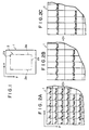
- a stimulable phosphor sheet 1 is exposed to a radiation by limiting a radiation exposure field 2 in a rectangular form as indicated by the chain line.
- the x and y axes are selected along two adjacent sides of the rectangular contour of the radiation exposure field 2 indicated by the chain line.
- the selected x and y axis directions generally coincide with the main scanning direction and the sub-scanning direction in preliminary read-out and/or final read-out.
- digital image signal values at respective positions on the stimulable phosphor sheet 1 are detected from image information obtained by the preliminary read-out.
- digital image signal values f(x,y) are obtained by detecting the light emitted by picture elements on the sheet 1 by use of a photoelectric read-out means in the preliminary read-out.
- the line of f(1,1), f(2,1), f(3,1), ..., in the x axis direction is taken as the first line
- the line of f(1,2), f(2,2), f(3,2), ..., is taken as the second line.
- the third line, the fourth line, and the subsequent lines are determined sequentially.
- the digital image signal values f(x,y) are pre-processed by one-dimensionally smoothing each set of three lines to obtain digital image signals F(x,y) at respective positions as shown in Figure 2B.
- the first line, the second line and the third line are one-dimensionally smoothed by calculating as shown below.
- the smoothing may be conducted at any line intervals.
- F(x,y) is expressed by
- the smoothing method since the arithmetic averaging is effected in the x axis direction when the edge of the radiation exposure field in the y axis direction is detected, the edge is not blurred in the y axis direction, and it is possible to decrease noise adversely affecting the edge extraction in the differentiation processing conducted later. Also, since the calculation is simple, the smoothing can be carried out quickly.
- digital image values F(x,y) at the respective positions are obtained, they are subjected to a differentiation processing in which differences between digital image values F(x,y) at positions present in the vicinity are calculated.
- differences ⁇ (x,y) between image values F(x,y) at positions adjacent in the x axis direction are calculated.
- the differentiation processing in the present invention embraces not only the case where the differences between image signals adjacent to each other are obtained but also the case where the differences between image values alternately adjacent to each other in the x axis direction, i.e. between F(1,2) and F(3,2) and so on, are calculated.
- the smoothing method and the differentiation processing method described above are mere examples, and the differentiation processing may be conducted without smoothing, or by using Laplacian operators.
- the aforesaid methods are advantageous since the calculation can be conducted quickly and the edge of the radiation exposure field can be detected more securely than the edges of the bone or the like in the object.
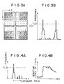
- the two-valued difference signal values ⁇ '(x,y) are added in the y axis direction.
- the difference signal values on the same x coordinate are added in the y axis direction by formulas ⁇ ' (1,2) + ⁇ ' (1,5) + ⁇ ⁇ ' (2,2) + ⁇ ' (2,5) + ⁇ ⁇ ' (3,2) + ⁇ ' (3,5) + ⁇ ⁇ ⁇ ⁇ and the histogram as shown in Figure 3B is created.
- the x coordinates at which the frequency is larger than a predetermined threshold value TL2 are judged as the positions of the exposure field contours 2a in the y axis direction.
- the positions (y coordinates) of exposure field contours 2b in the x axis direction shown in Figure 1 are detected in the same manner. Specifically, image signals F(x,y) at the respective positions are detected by smoothing a plurality of lines of f(x,y) in the y axis direction, and differences ⁇ (x,y) between F(x,y) adjacent in the y axis direction are calculated. The differences ⁇ (x,y) are converted into two-valued system by using a predetermined threshold value TL1', and the two-valued signals are added in the x axis direction to create a histogram.
- the y coordinates at which the frequency exceeds a predetermined threshold value TL2' are judged as the positions of the exposure field contours 2b in the x axis direction.
- judgement is made in the same manner as for the contours 2a in the y axis direction.
- the radiation exposure field is detected as described above, and then the read-out conditions for the final read-out are adjusted on the basis of the preliminary read-out image information within the radiation exposure field.
- the read-out conditions may be adjusted in various manners, for example, by obtaining a histogram of the light emission amounts within the radiation exposure field as described above, calculating the maximum light emission amount Smax and the minimum light emission amount Smin from the histogram, and adjusting the read-out conditions such as the read-out gain (sensitivity) and the scale factor (latitute) on the basis of Smax and Smin.
- the final read-out is carried out by use of the adjusted read-out conditions.
- the read-out region should preferably be limited within the detected radiation exposure field.
- the image information obtained by the preliminary read-out is proportional to the level of radiation energy incident on the stimulable phosphor sheet, predetermined positions are set on the sheet, and differences between image signal values at positions in the vicinity are calculated. Since the differences become large when the exposure field contour is present between the compared positions, the position of the radiation exposure field is detected on the basis of the differences. In some cases, the differences at the boundary between soft tissues and the bone or the like within the radiation exposure field may become nearly equal to those at the exposure field contour, and it becomes necessary to discriminate between them. In such a case, the exposure field contour may be detected in various manners, for example, by utilizing the shape of the exposure field known in advance as in the aforesaid embodiment and adding the differences along the contour of the exposure field shape.
- the aforesaid embodiment may also be applied to the cases of radiation exposure fields of various shapes other than rectangle, for example, circular radiation exposure fields, by calculating the differences in appropriate directions in accordance with the shapes of the radiation exposure fields and by using appropriate judgement methods such as addition.
- the radiation exposure field may also be detected by, in the differentiated image constituted by the differentiated values obtained by the differentiation processing, selecting an arbitrary position at which the differentiated value is the maximum or not smaller than a predetermined value as a first remark point, finding a position at which the differentiated value is the maximum among the positions adjacent the first remark point and selecting said position as a second remark point, finding a position at which the differentiated value is the maximum among the positions adjacent the second remark point and outside of the previous remark point and selecting said position as a third remark point, thereafter repeating the step of finding the third remark point to find new remark points sequentially until a position adjacent said first remark point is found as a new remark point, and recognizing the inside of the closed curve passing through the found remark points as the radiation exposure field.
- the positions adjacent the remark point need not necessarily be all of the positions which are adjacent the remark point.
- the shape of the radiation exposure field is known in advance, only a part of the positions adjacent the remark point that are fixed by the shape of the radiation exposure field may be considered as the aforesaid positions adjacent the remark point.
- digital image signal values at respective positions on the stimulable phosphor sheet may be detected by conducting a pre-processing such as a spatial filter processing.
- the positions on the sheet may be determined in the picture element unit, and the digital image signal value at each position may be calculated on the basis of the preliminary read-out image information on a plurality of the picture elements corresponding to the position and positions therearound.
- the calculation method it is possible to use the median filter processing in which the median value of the image information (quantization levels) at a predetermined picture element (position) and the picture elements (positions) therearound is employed as the image information at the predetermined picture element (position).
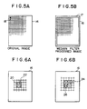
- Figure 5A shows an original image 14 constituted by the preliminary read-out image information at respective picture elements indicated by cells.
- Figure 5B shows a median filter processed image 16 constituted by digital image signal values obtained at respective positions by carrying out the median filter processing on the image information at respective picture elements in the original image.
- the respective positions in the processed image 16 are also referred to as the picture elements.
- a mask 18 having a predetermined size for example, the 3x3 size covering 3x3 picture elements, is positioned on the original image 14 so that the mask center coincides with a predetermined picture element indicated by hatching in Figure 5A.
- the median value of the image information at nine picture elements covered by the mask is digitized and detected as the digital image signal value at the predetermined picture element.
- This processing is conducted for all picture elements of the original image 14 outside of those at the peripheral portion 17.
- digital image signal values at the picture elements are detected, and the median filter processed image 16 constituted by the digital image signal values is obtained.
- the processing image 16 becomes smaller by the picture elements at the peripheral portion 17 than the original image 14.
- zero quantization level may be assigned as the image signals to the picture elements at the peripheral portion 17.
- the mask size is not limited to 3x3.
- the median filter processing may be conducted by assuming that picture elements having the same quantization levels as those of the picture elements at the peripheral portion of the original image are present around the original image 14. The median filter processing is advantageous in that noise causing the quantization level of the picture element to become extremely higher or lower than those of the surrounding picture elements can be eliminated and that the information on the exposure field contour is not blurred.
- the aforesaid pre-processing is not limited to the median filter processing and may be any spatial filter processing insofar as unnecessary information such as noise is eliminated while the necessary information on the exposure field contour or the like is maintained.
- the digital image signal values are subjected to a differentiation processing, and a differentiated image constituted by the differentiated values is created.
- the differentiation processing may be conducted in any manner, for example, as described below.
- Figures 6A and 6B show processed images in which each cell indicates one position.
- a mask 22 having a size of 2x2 picture elements may be used as shown in Figure 6A.
- the mask 22 is positioned so that the left upper portion thereof coincides with the predetermined position 20.
- the differentiating calculation is conducted for respective positions.
- other differentiation formulas may be used.
- a second order differentiation processing may be conducted.
- a mask 24 having the size of 3x3 picture elements may be positioned so that the mask center coincides with a predetermined position 26.
- the contour of the radiation exposure field is detected on the basis of the differentiated image created as described above. Since the quantum level of the differentiated value of the image signal at the exposure field contour becomes higher than those of differentiated values of image signal at the other positions as described above, the position in the differentiated image at which the differentiated value is the maximum or not smaller than a value predetermined appropriately may be recognized as the exposure field contour. Also, the exposure field contour is formed by one closed curve. Therefore, when one position at which the exposure field contour is present is remarked, there is always a new position at which the exposure field contour is present among the surrounding positions adjacent the remarked position, and the differentiated value at the new position is larger than those at the surrounding positions adjacent the new position. Stated differently, the exposure field contour is present at least at the position exhibiting the maximum differentiated value among the adjacent positions.
- the exposure field contour is detected by sequentially tracking the positions in the differentiated image at which the exposure field contour is present.
- the embodiment comprises the step of detecting the tracking start point a first remark point, and the step of tracking the contour positions from the first remark point.
- the differentiated image is scanned to find an arbitrary position at which the differentiated value is the maximum or not smaller than a predetermined value, and the found position is selected as the first remark point.
- the position at which the differentiated value is not smaller than the predetermined value may be regarded as the position where the exposure field contour is present.
- the position at which the differentiated value is the maximum may be regarded as the position at which the exposure field contour is present. Therefore, one of the positions at which the exposure field contour is present is first detected as described above, and is selected as the first remark point.
- tracking of the exposure field contour is started from the first remark point to recognize the radiation exposure field.
- the position at which the differentiated value is the maximum is found from among the positions adjacent the first remark point, and is selected as a second remark point.
- the position at which the differentiated value is the maximum is then found from among the positions adjacent the second remark point and outside of the previous remark point (i.e. the first remark point), and is selected as a third remark point.
- the step of finding the third remark point is repeated to find new remark points sequentially. When a position adjacent the first remark point is found as the new remark point, the inside of the closed curve passing through the remark points thus found is recognized as the radiation exposure field.
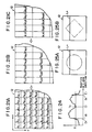
- the above-mentioned tracking may be conducted by use of masks as shown in Figures 7 and 8A to 8D.
- the mask shown in Figure 7 has a size of 3x3 picture elements.
- the mask is first positioned as shown in Figure 9A so that the mask center hatched in Figure 7 coincides with the first remark point A which is present on the exposure field contour in a differentiated image 28 and which has been detected as described above.
- the position exhibiting the maximum differentiated value among the positions within the mask and outside of the first remark point A is selected as the second remark point B.
- the mask is moved until the mask center coincides with the second remark point B, and the position exhibiting the maximum differentiated value among the positions within the mask and outside of the previous remark points, i.e.
- the first remark point A and the second remark point B is selected as the third remark point C.
- the fourth remark point D and the fifth remark point E are respectively found as shown in Figures 9C and 9D.
- Figure 9E When a position adjacent the first remark point A is found as a new n'th remark point F as shown in Figure 9E, the inside of a closed curve 30 passing through the found remark points A to F is recognized as a radiation exposure field 10.
- the arrows indicate the tracking direction for finding the exposure field contour.
- the masks shown in Figures 8A to 8D are fabricated to cover only a part (four picture elements) adjacent the remark point and are selected in accordance with the tracking direction.
- the arrows indicate the tracking directions when the masks are used.
- the differentiated image is scanned to find the position where the differentiated value is the maximum and the position is selected as the first remark point A, the position exhibiting the maximum differentiated value is found from among positions I, II, III and IV adjacent the first remark point A in the x and y axis directions, and tracking is started from the first remark point A towards the position exhibiting the maximum differentiated value. For example, when the position I exhibits the maximum differentiated value, tracking is started leftwardly towards the position I.
- the mask shown in Figure 8A is used.
- the mask is positioned so that the mask portion hatched in Figure 8A coincides with the first remark point A.
- the position exhibiting the maximum differentiated value among the positions within the mask and outside of the first remark point A is found as the second remark point B.
- the mask is moved until the mask portion hatched in Figure 5A coincides with the second remark point B, and the position exhibiting the maximum differentiated value among the positions within the mask and outside of the previous remark points, i.e. the first and second remark points A and B is found as the third remark point. This step is repeated to find new remark points sequentially.
- the mask shown in Figure 8D is used to continue remark point detection as shown in Figure 10E.
- the mask shown in Figure 8A is used to continue remark point detection as shown in Figure 10F.
- the inside of the closed curve passing through the found remark points is regarded as the radiation exposure field 10.
- the arrows indicate the tracking directions.
- the position exhibiting the maximum differentiated value in the differentiated image is selected as the first remark point.
- tracking may be conducted in the same manner.
- the masks of Figures 8A to 8D since the mask used is different in accordance with the tracking direction, it is necessary to determine the tracking direction. In this case, as shown in Figure 10G, it is also possible to select the scanning direction as indicated by the arrow J for finding the first remark point A as the tracking direction, and initially use the mask for the direction.
- This embodiment is applicable also to the case of subdivision image recording in which the stimulable phosphor sheet is divided into some divisions and image recording is conducted on each division by limiting the radiation exposure field.
- the embodiment since the radiation exposure field is present at each division, the embodiment may be applied to each division by obtaining in advance the information on the subdivision image recording.
- the second and subsequent remark points are selected by sequentially finging the position exibiting the maximum differentiated value from among the positions adjacent the preceding remark point and outside of the previous remark point or points.
- the position when there is only one position at which the differentiated value is not smaller than the predetermined value among the positions adjacent the preceding remark point, the position may be selected as the next remark point.
- a position may be selected as the next remark point in accordance with a priority sequence predetermined for the positions adjacent the preceding remark point.
- an arbitrary position or the position exhibiting the maximum differentiated value may be selected as the next remark point from such two or more positions.
- the position exhibiting the maximum differentiated value among the positions adjacent the preceding remark point may be selected as the next remark point.
- the tracking may be conducted as described below by use of the masks shown in Figures 11 and 12A to 12D.
- Figures 13A to 13E show the tracking method using the mask of Figure 11.
- the mask is positioned so that the mask center hatched in Figure 11 coincides with the first remark point A detected as described above to be present on the exposure field contour, and a position at which the differentiated value is not smaller than the predetermined value among the positions within the mask and outside of the first remark point A is selected as the second remark point.
- the position exhibiting the maximum differentiated value may be selected.
- the differentiated values at the positions corresponding to the portions a and e are not smaller than the predetermined value.
- the differentiated value at the portion e is larger than that at the portion a, the position corresponding to the portion e is selected as the second remark point B.
- the mask is moved until the mask center coincides with the second remark point B, and the position at which the differentiated value is not smaller than the predetermined value among the positions within the mask and outside of the first remark point A and the second remark point B is selected as the third remark point C.
- the third remark point is selected in accordance with the predetermined priority sequence which may be determined in various manners.
- the priority is predetermined counterclockwise in the sequence of b, c, d, e, f, g and h starting from the portion a.
- the positions corresponding to the portions e and f exhibit the differentiated values not smaller than the predetermined value among the positions expected as the third remark point, and the position corresponding to the portion e which has the priority to that at the portion f is selected as the third remark point C.
- the subsequent remark points are selected in the same manner.
- the position adjacent the first remark point A is selected as a new remark point as shown in Figure 13E
- the inside of the closed curve 30 passing through the first remark point A to the n'th remark point F is recognized as the radiation exposure field 10.
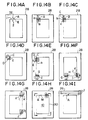
- the initial tracking direction is selected leftwardly towards the position I in the same manner as described with reference to Figure 10A. Since the tracking direction is leftward, the mask of Figure 12A is used and positioned so that the hatched mask portion coincides with the first remark point A as shown in Figure 14B. Among the positions within the mask, the position at which the differentiated value is not smaller than the predetermined value and which is outside of the first remark point A is found and selected as the second remark point. In the case shown, since only the position corresponding to the mask portion b exhibits a differentiated value not smaller than the predetermined value, the position is selected as the second remark point B.
- the mask is moved until the hatched mask portion coincides with the second remark point B, and the position at which the differentiated value is not smaller than the predetermined value among the positions within the mask and outside of the previous remark points, i.e. the first and second remark points A and B, is selected as the third remark point.
- the positions corresponding to the portion b and c exhibit differentiated values not smaller than the predetermined value and the priority is predetermined in the sequence of a, b, c and d as indicated by the long arrow in Figure 12A, the position corresponding to the portion b is selected as the third remark point C.
- the mask of Figure 12A is used and moved until the hatched mask portion coincides with the third remark point C as shown in Figure 13D.
- the position at which the differentiated value is not smaller than the predetermined value is selected as the fourth remark point.
- the position at the mask portion d exhibits the differentiated value not smaller than the predetermined value, the position is selected as the fourth remark point D.
- the mask of Figure 12B is used and moved until the hatched mask portion coincides with the fourth remark point D.
- the position at which the differentiated value is not smaller than the predetermined value is found as the fifth remark point.
- the position is selected as the fifth remark point E.
- New remark points are then found sequentially in the same manner.
- the mask is positioned as shown in Figure 14E, and the next remark point is found.
- the position is selected as the next remark point G.
- the mask of Figure 12C is used and positioned so that the hatched mask portion coincides with the remark point G as shown in Figure 14F.
- the next remark point is selected in the manner as described above.
- the tracking direction may be maintained the same and the mask may not be changed when the next remark point appears at portion a, b or c, and the mask may be changed only when the next remark point appears at the portion d. This also applies to the case of the mask shown in Figure 11.
- the scanning direction for finding the first remark point A as indicated by the arrows J may be selected as the tracking direction as shown in Figure 14I, and the mask for the selected direction may be used initially.
- the radiation exposure field may also be detected by creating the differentiated image constituted by the differentiated values at the respective positions, preparing a plurality of multi-valued image templates each having a portion corresponding to the exposure field contour and provided with values different between positions within said portion corresponding to the exposure field contour and positions within the other portions wherein the shape and the size of said portion corresponding to the exposure field contour are different between said templates in accordance with the shape and the size of exposure field contour in the limitation of the radiation exposure field effected in actual image recording, calculating the correlations between the differentiated values on said differentiated image or values obtained by processing the differentiated values and the values on the respective templates, and recognizing the inside of the exposure field contour corresponding portion of the template exhibiting the maximum correlation as the radiation exposure field.
- Such an embodiment will hereinbelow be described with reference to Figures 15 to 18.
- Figure 15 is an enlarged view of the left upper corner portion of the stimulable phosphor sheet 1 of Figure 1 and shows the digital image signals f(1,1), f(1,2), ... at picture elements (1,1), (1,2), ...
- the positions on the stimulable phosphor sheet are set in the picture element unit.
- the digital image signal values are subjected to the two-dimensional first order differentiation processing.
- Two-dimensional first order differentiated values ⁇ at respective positions are then calculated on the basis of the differentiated values ⁇ ' and ⁇ ", for example, by adding the absolute values thereof.
- ⁇ (1, 1)
- ⁇ (1, 2)
- ⁇ ⁇ ⁇ ⁇ ⁇ (2, 1)
- ⁇ (2, 2)
- a differentiated image constituted by the differentiated values ⁇ at respective positions is created.
- the differentiated values ⁇ are always positive.
- the differentiated values may become negative in accordance with the positions on the stimulable phosphor sheet, for example, when the differentiated image is created by one-dimensional first order differentiation processing, the absolute values thereof are handled as the differentiated values on the differentiated image.
- the differentiated image is created by directly using the differentiated values ⁇ in this embodiment, it is also possible to create the differentiated image by converting the differentiated values ⁇ into the two-valued system by use of a predetermined threshold value.
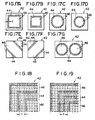
- FIGS 17A to 17G show examples of a plurality of the multi-valued image templates prepared in advance.
- Each template 42 has an exposure field contour corresponding portion 44 hatched in the drawing. Respective positions within the exposure field contour corresponding portion 44 are provided with values, for example, not smaller than 1, the respective positions within the other portions 46 are provided, for example, with a value 0.
- the shape and the size of the exposure field contour corresponding portion 44 are different between the templates 42 in accordance with the shape and the size of the exposure field contour in the exposure field limitation effected in actual image recording.
- the size of the template 42 should preferably be equal to that of the stimulable phosphor sheet 1 shown in Figure 1 (or the differentiated image.
- the exposure field contour corresponding portion 44 has a predetermined width t which may correspond to the total width of two or three positions as shown in Figures 18 and 19, and may correspond to the width of one position or the total width of four or more positions.
- shape of exposure field contour corresponding portion is meant the rectangular shape as shown in Figures 17A and 17B, the circular shape as shown in Figures 17C and 17D, or the like.
- size of exposure field contour corresponding portion is meant the length of one side of the rectangle, the diameter of the circle, or the like.
- the templates 42 shown in Figures 17E and 17F have the exposure field contour corresponding portion 44 for the case where the radiation exposure field is limited obliquely, and that shown in Figure 17G has the exposure field contour corresponding portion 44 for the case where the radiation exposure field is limited in the circular form and the subdivision image recording is conducted.
- the respective positions on the template 42 correspond to the respective positions on the differentiated image. However, they need not necessarily correspond in one-to-one relation and, for example, one position on the template 42 may correspond to 2x2 positions adjacent to each other on the differentiated image.
- the respective positions within the exposure field contour corresponding portion 44 may be provided with the same value, i.e. a value 1. Or, as shown in Figure 19, they may be provided with two values, i.e. 2 at the center and 1 on two sides. Of course, they may be provided with three or more values, and the values may be assigned in any manner.
- the correlations between the differentiated image and the template images are calculated. That is, similarity between the images is digitized by calculating as described below. Thereafter, the inside of the exposure field contour corresponding portion of the template image exhibiting the maximum correlation is recognized as the radiation exposure field.
- the differentiated values i.e. the differentiated values themselves or the values obtained by converting the differentiated values into the two-valued system
- the total of the products is calculated.
- values at the corresponding positions are multiplied.
- the respective differentiated values at the four positions are multiplied by the value at the single position on the template. After multiplication between the corresponding positions is carried out over the whole area of the template, the products are added.
- the differentiated values at positions where the exposure field contour is present are larger than those at the other positions as described above, the sum of the products in the case of the template having the exposure field contour corresponding portion 44 which just coincides with the exposure field contour becomes larger than that in the cases of the other templates. Therefore, when many templates having various exposure field contour corresponding portions in accordance with the shapes and sizes of expected exposure field contours are prepared and the template exhibiting the maximum product sum is selected by conducting the multiplication between the differentiated image and the respective templates as described above and adding the products, it may be regarded that the actual exposure field contour is present within the exposure field contour corresponding portion 44 of the selected template. Thus it is possible to recognize that the inside of the exposure field contour corresponding portion 44 as the radiation exposure field. When the portion 44 has some width, the inside of any position within the portion 44, for example, the inside of the inner edge, the outer edge or the center of the width portion, may be recognized as the radiation exposure field.
- digital image signal values at respective positions on the stimulable phosphor sheet or a sheet portion having one radiation exposure field are detected on the basis of the image information obtained by the preliminary read-out, the respective positions forming in line in a predetermined direction on said stimulable phosphor sheet or said sheet portion are set as a line, the digital image signal values on said line are subjected to the differentiation processing, two positions at which the absolute values of the differentiated values exceed a predetermined value To are selected as prospective exposure field contour points on said line, the minimum value T1 of said digital image signal values on said line between said prospective exposure field contour points is detected, two outer positions at which said digital image signal values are equal to said minimum value T1 on said line are detected as exposure field contour points on said line, said detection of said exposure field contour points is conducted for respective lines within a predetermined range on said stimulable phosphor sheet or said sheet portion, and the inside of a contour line or lines passing through said exposure field contour points on the respective lines is recognized as the radiation exposure field.
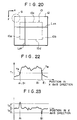
- Figure 20 shows a stimulable phosphor sheet 12 having one radiation exposure field 10
- Figure 21A is an enlarged view of the portion G of the sheet 12 shown in Figure 20.
- the respective positions on the sheet 12 are set in the picture element unit.
- the respective positions forming a line in a predetermined direction on the sheet 12 are set as one line.
- the line setting may be effected in only one direction or in two directions. Of course, it may also be effected in more directions.
- lines are set in the x axis and y axis directions normal to each other. Specifically, positions (1,1), (2,1), (3,1), (4,1), (5,1), ... forming in line in the x axis direction are set as the first x axis line Lx1, and positions (1,2), (2,2), (3,2), (4,2), (5,2), ... forming in line are set as the second x axis line Lx2.
- the third x axis line Lxa, the fourth x axis line Lx4, ... are set in the same manner. Also, positions (1,1), (1,2), (1,3), (1,4), ...
- first y axis line Ly1 positions (2,1), (2,2), (2,3), (2,4), ... are set as the second y axis line Ly2.
- the third y axis line Ly3, the fourth y axis line Ly4, ... are set in the same manner.
- the digital image signal values on each line are subjected to the differentiation processing to detect exposure field contour points on the line as described below by taking the n'th x axis line Lxn shown in Figure 20 as an example.
- Figure 22 shows the levels of the digital image signal at the respective positions on the line Lxn
- Figure 23 shows the differentiated values obtained at the respective positions by the differentiation processing of the digital image signal values on the line Lxn.
- differentiated values ⁇ at the respective positions on the line Lxn are obtained as shown below by conducting the first order differentiation of the digital image signals on the line Lxn.
- positions Ai and Bi at which the absolute values of the differentiated values are not smaller than a predetermined value To are selected as prospective exposure field contour points on the line Lxn. Since the exposure field contour line is generally a closed curve, one line intersects with the closed contour curve at two points, and therefore two contour points are present on one line. As a result, two prospective contour points are detected.
- an image signal TA at the prospective exposure field contour point Ai is the minimum digital image signal value between the prospective exposure field contour points Ai and Bi.
- an image signal TC at a position Ci between the positions Ai and Bi may become the minimum value T1.
- the digital image signal value TA at the prospective exposure field contour points Ai is equal to the minimum value T1
- the positions Di and Ei are automatically detected as the two outer positions.
- the digital image signal value TC at the position Ci between Ai and Bi is equal to the minimum value T1 as shown in Figure 24
- three positions (Di, Ci and Ei) are detected as the positions at which the image signals are equal to the minimum value T1.
- the outer positions Di and Ei outside of Ci are detected as the exposure field contour points.
- Detection of the exposure field contour points on one line as described above is conducted for respective x axis lines Lx over the whole area in the y axis direction, and contour lines 10a and 10b in the y axis direction shown in Figure 20 are detected by connecting the exposure field contour points on the respective lines Lx.
- contour points on an arbitrary y axis line Lyn are detected, and detection of the contour points is conducted for the respective y axis lines Ly over the whole area in the x axis direction.
- Contour lines 10c and 10d in the x axis direction are detected by connecting the contour points on the respective lines Ly.
- the inside of the contour lines 10a, 10b, 10c and 10d, i.e. the region surrounded thereby, is recognized as the radiation exposure field.
- detection of the contour points is carried out for the lines over the whole region on the sheet 12. However, it may be conducted only for lines within a predetermined region on the sheet 12. For example, when the region of the radiation exposure field is approximately known, the contour point detection may be conducted only for the lines within the region. Or, the contour point detection may first be conducted for the x axis lines Lx to detect the contour lines 10a and 10b in the y axis direction, and then be conducted only for the y axis lines Ly between the contour lines 10a and 10b.
- contour point detection need not necessarily be conducted for lines in two directions.
- the whole exposure field contour may be detected by conducting the contour point detection only for the lines Lx in the x axis direction.
- exposure field detection may be conducted by setting the positions as described below.
- the image signal values F are subjected to the differentiation processing for each line in the x axis direction to obtain differentiated values ⁇ at the respective positions, and the exposure field contour line in the y axis direction is detected by using the differentiated values ⁇ in the same manner as described above.
- Digital image signal values F at the respective positions are calculated by arithmetic averaging as described above, and are differentiated for each line in the y axis direction to obtain differentiated values ⁇ , which are then used to detect the exposure field contour line in the x axis direction in the same manner as described above.
- the respective positions forming in line in a predetermined direction on said stimulable phosphor sheet are set as a line, said digital image signal values on said line are subjected to the differentiation processing, at least one position at which the absolute value of the differentiated value exceeds a predetermined value To is selected as an exposure field contour point on said line, and when there is an undetected latent contour point among a plurality of the exposure field contour points actually present on said line, the digital image signal value at said position at which the absolute value of the differentiated value exceeds the predetermined value To on said line is detected, a characteristic value Th of said digital image signal is determined from said digital image signal value, a position outside of said position at which the absolute value of the differentiated value exceeds the predetermined value To or outside of a position in the vicinity of said position among those at which the digital image signal values are equal to said characteristic value Th on said line is recognized as said latent contour point, said detection of said exposure field contour points is conducted for respective lines within a predetermined
- a stimulable phosphor sheet 50 is divided into two sections, and a radiation image is recorded in each section by limiting the radiation exposure field.
- respective positions on the stimulable phosphor sheet are set in the picture element unit as shown in Figure 21A, and the lines Lxn and Lyn are set in the same manner as described with reference to Figure 20.
- exposure field contour points are detected by conducting the differentiation processing and a threshold value processing using a predetermined value To for each line as described below.
- Figure 27 shows the levels of the digital image signal at the respective positions on the line Lxn
- Figure 28 shows the differentiated values obtained at the respective positions by the differentiation processing of the digital image signal values on the line Lxn.
- the differentiated values at the respective positions on the line Lxn are calculated in the same manner as described with reference to Figure 23, and then positions A, C and D at which absolute values of the differentiated values exceeds the predetermined value To are detected as the exposure field contour points on the line Lxn.
- the absolute values of the differentiated values do not always exceed the predetermined value To.
- the change in the image signals at the right contour line 52b may be small as shown in Figure 27, and the absolute value of the differentiated value at the position B of the right contour line 52b may not exceed the predetermined value To as shown in Figure 28.
- digital image signals TA, TC and TD on the line Lxn at the contour points A, C and D detected by the threshold value processing using the predetermined value To are detected. Then, a characteristic value Th of the digital image signal values TA, TC and TD is determined on the basis of these digital image signal values.
- the characteristic value Th may be any value insofar as it is based on the image signals TA, TC and TD, and may be the minimum value, average value, median value or maximum value of TA, TC and TD.
- TA which is the minimum value between the three values is adopted as the characteristic value Th.
- positions A', B', C' and D' at which the digital image signals are equal to the characteristic value Th are detected, and the position B' outside of the positions A', C' and D' which are equal to or near the positions A, C and D exhibiting the absolute values of the differentiated values exceeding the predetermined value To is recognized as the latent contour point.
- the positions A, C and D and the positions A', C' and D' equal to or near the positions A, C and D respectively correspond to the same contour points, and the other position B' corresponds to the latent contour point which could not be detected by the aforesaid differentiation processing and the threshold value processing.
- Detection of the all contour points on the x axis line Lxn is conducted for the x axis lines Lx over the whole region in the y axis direction, and the contour lines 52a, 52b, 54a and 54b in the y axis direction are detected by connecting the contour lines on the respective lines Lx.
- the characteristic value Th is determined from the digital image signal at the single contour point.
- the digital image signal value itself may be selected as the characteristic value Th.
- the contour points on the lines Ly are connected to determine the contour lines 52c, 52d, 54c and 54d in the x axis direction.
- the inside of the contour lines 52c, 52d, 54c and 54d and the contour lines 52a, 52b, 54a and 54b, i.e. the region surrounded by these contour lines, is recognized as the radiation exposure field.
- the respective positions forming a line in a predetermined direction on said stimulable phosphor sheet are set as a line, said digital image signal values on said line are subjected to the differentiation processing, at least one position at which the absolute value of the differentiated value exceeds a predetermined value To is selected as a prospective exposure field contour point on said line, the digital image signal value at said prospective exposure field contour point on said line is detected, a characteristic value Th of said digital image signal is determined from said digital image signal value, positions at which the digital image signal values are equal to said characteristic value Th on said line are detected as the exposure field contour points on said line, said detection of said exposure field contour points is conducted for respective lines within a predetermined range on said stimulable phosphor sheet, and the inside of a contour line or lines passing through said exposure field contour points on the respective lines is recognized as the radiation exposure field.
- This embodiment is similar to that described with reference to Figures 26, 27 and 28, except that the positions A, C and D at which the absolute values of the differentiated values exceed the predetermined value To as shown in Figure 28 are selected as prospective exposure field contour points, and the positions A', B', C' and D' at which the digital image signals are equal to the characteristic value Th as shown in Figure 27 are detected as the exposure field contour points on the line Lxn. Stated differently, the positions (A' to B', C' to D')at which the digital image signals are not smaller than the characteristic value Th are judged as the exposure field contour region on the line Lxn.
- the embodiment mentioned last is applicable not only to the case where the contour line 52b cannot be detected by the differentiation processing and the threshold value processing but also to the case where all of the contour lines can be detected thereby.
- the method of detecting the contour line positions by the differentiation processing and the threshold value processing it is necessary to to judge whether all of the contour line positions could be detected or not.
- some processing must be conducted for detecting the contour line.
- the algorithm up to the final exposure field detection becomes complicated.
- all of the contour line positions can be detected automatically regardless of whether they could be detected by the initial differentiation processing and the threshold value processing or not, and the algorithm becomes simple.
Landscapes
- Physics & Mathematics (AREA)
- General Physics & Mathematics (AREA)
- Radiography Using Non-Light Waves (AREA)
- Apparatus For Radiation Diagnosis (AREA)
- Image Analysis (AREA)
Claims (9)
- Procédé de détection du contour d'un champ d'exposition d'une image de radiation latente, ledit champ d'exposition comprenant au moins un objet qui diffuse le rayonnement en dehors dudit champ d'exposition, lors d'un traitement d'extraction d'image dans lequel l'image est extraite photoélectriquement pour obtenir des informations d'image sous la forme de valeurs de signaux d'image numériques correspondant au niveau de densité d'image, le procédé comprenant les étapes de détection de valeurs de signaux d'image numériques (f(x, y)) à des positions respectives sur ladite image sur la base des informations d'image obtenues par ladite extraction photoélectrique, de soumission desdites valeurs de signaux d'image numériques à un traitement de différenciation uni ou bidimensionnel du premier ordre ou d'ordre supérieur pour obtenir des valeurs différenciées (Δ, a', e', δ, δ', δ"), et de détection que le contour de champ d'exposition est présent à une position où le critère satisfait qu'une valeur différenciée par rapport à ladite position est plus grande qu'une valeur de seuil prédéterminée.
- Procédé tel que défini dans la revendication 1, dans lequel lorsque ledit champ d'exposition est rectangulaire, la détection dudit contour de champ d'exposition effectuée par l'utilisation desdites valeurs différenciées est effectuée en sélectionnant les axes x et y le long de deux côtés voisins du rectangle, en calculant des valeurs différenciées pour les valeurs de signaux d'image le long de chacune de plusieurs lignes dans la direction de l'axe x, et en additionnant lesdites valeurs différenciées à chacune des abscisses x dans ladite direction y pour former une première somme pour tester la position du contour de champ d'exposition sur l'axe x, en calculant les valeurs différenciées pour les valeurs de signaux d'image le long de chacune de la pluralité des colonnes dans la direction de l'axe y, et en additionnant lesdites valeurs différenciées à chacune des ordonnées y dans la direction de l'axe x pour former une seconde somme pour tester la position dudit contour de champ d'exposition sur l'axe y où une ligne de contour de champ d'exposition le long d'un quelconque desdits axes est supposée à une position de coordonnée respective de celui-ci où une somme respective de ladite première ou seconde somme est plus grande qu'une valeur de seuil prédéterminée.
- Procédé tel que défini dans la revendication 1, dans lequel ledit champ d'exposition est détecté dans une image différenciée constituée par lesdites valeurs différenciées obtenues par ledit traitement de différenciation, en sélectionnant une position arbitraire à laquelle la valeur différenciée est le maximum ou n'est pas plus petite qu'une valeur prédéterminée comme un premier point de remarque, en recherchant d'une position à laquelle la valeur différenciée est le maximum parmi les positions voisines dudit premier point de remarque et en sélectionnant ladite position comme un second point de remarque, en recherchant une position à laquelle la valeur différenciée est le maximum parmi les positions voisines dudit second point de remarque et en dehors du point de remarque précédent et en sélectionnant ladite position comme un troisième point de remarque, en répétant ensuite l'étape de recherche dudit troisième point de remarque pour trouver séquentiellement de nouveaux points de remarque jusqu'à ce qu'une position voisine dudit premier point de remarque soit trouvée comme un nouveau point de remarque, et en déterminant une courbe fermée passant par les points de remarque trouvés où ladite courbe fermée constitue ledit contour de champ d'exposition.
- Procédé tel que défini dans la revendication 1, dans lequel ledit champ d'exposition est détecté dans une image différenciée constituée par lesdites valeurs différenciées obtenues par ledit traitement de différenciation, en sélectionnant une position arbitraire à laquelle la valeur différenciée est le maximum ou n'est pas plus petite qu'une valeur prédéterminée comme un premier point de remarque, en recherchant une position à laquelle la valeur différenciée n'est pas plus petite que la valeur prédéterminée parmi les positions voisines dudit premier point de remarque, et en sélectionnant de ladite position comme un second point de remarque, en recherchant une position à laquelle la valeur différenciée n'est pas plus petite que la valeur prédéterminée parmi les positions voisines dudit second point de remarque et en dehors du point de remarque précédent et en sélectionnant ladite position comme un troisième point de remarque, en répétant ensuite l'étape de recherche dudit troisième point de remarque pour trouver séquentiellement de nouveaux points de remarque jusqu'à ce qu'une position voisine dudit premier point de remarque soit trouvée comme un nouveau point de remarque, et en déterminant une courbe fermée passant par les points de remarque trouvés de sorte que ladite courbe fermée constitue ledit contour de champ d'exposition où lorsqu'une pluralité de positions auxquelles des valeurs différenciées ne sont pas plus petites que la valeur prédéterminée sont présentes parmi lesdites positions voisines à l'étape de recherche dudit second et desdits points de remarque nouveaux qui suivent, une direction de priorité est déterminée à l'avance pour lesdites positions voisines, et le nouveau point de remarque suivant est sélectionné selon ladite direction de priorité à partir de la pluralité desdites positions auxquelles les valeurs différenciées ne sont pas plus petites que la valeur prédéterminée, et où lorsqu'il n'y a pas de position à laquelle la valeur différenciée n'est pas plus petite que la valeur prédéterminée parmi lesdites positions voisines à l'étage de recherche dudit second et desdits nouveaux points de remarque qui suivent, la position montrant la valeur différenciée maximum parmi lesdites positions voisines est sélectionnée comme le nouveau point de remarque suivant.
- Procédé tel que défini dans la revendication 1, dans lequel ledit champ d'exposition est détecté en créant une image différenciée constituée par lesdites valeurs différenciées aux positions respectives, en préparant une pluralité de modèles d'image multi-valeur ayant chacun une partie correspondant à un contour de champ d'exposition et pourvus de valeurs différentes entre des positions avec ladite partie correspondant au contour de champ d'exposition et aux positions dans les autres parties où la forme et la dimension de ladite partie correspondante au contour de champ d'exposition sont différentes entre lesdits modèles selon la forme et la dimension du contour de champ d'exposition dans la limitation dudit champ d'exposition effectuée dans un enregistrement d'image réel, en calculant les corrélations entre lesdites valeurs différenciées de ladite image, ou les valeurs obtenues en traitant lesdites valeurs différenciées et les valeurs sur les modèles respectifs, et en déterminant ledit contour de champ d'exposition pour qu'il soit la partie d'image qui correspond à la partie correspondant à un contour de champ d'exposition de celui desdits modèles qui montre la corrélation maximum pour reconnaître l'intérieur dudit contour de champ d'exposition comme ledit champ d'exposition.
- Procédé tel que défini dans la revendication 1, dans lequel les valeurs de signaux d'image numériques à des positions respectives sur l'image ou une partie d'image ayant un champ d'exposition sont détectées sur la base des informations d'image obtenues par l'extraction photoélectrique, les positions respectives formant une ligne dans une direction prédéterminée sur ladite image ou ladite partie d'image sont déterminées comme une ligne, lesdites valeurs de signaux d'image numériques sur ladite ligne sont soumises à un traitement de différenciation, deux positions auxquelles les valeurs absolues des valeurs différenciées dépassent une valeur prédéterminée (To) sont sélectionnées comme des points de contour de champ d'exposition prospectifs sur ladite ligne, la valeur minimum (T1) desdits signaux d'image numériques sur ladite ligne entre lesdits points de contour de champ d'exposition prospectifs est détectée, les deux positions marginales externes auxquelles lesdites valeurs de signaux d'image numériques sont égales à ladite valeur minimum (T1) sur ladite ligne sont déterminées comme des points de contour de champ d'exposition sur ladite ligne, ladite détection desdits points de contour de champ d'exposition est effectuée pour les lignes respectives dans un intervalle prédéterminé sur ladite image où ladite partie d'image, et la partie de l'image enfermée par une ligne de contour ou des lignes passant par lesdits points de contour de champ d'exposition sur les lignes respectives est déterminée comme ledit champ d'exposition.
- Procédé tel que défini dans la revendication 1, dans lequel les positions respectives formant une ligne dans une direction prédéterminée sur ladite image sont déterminées comme une ligne, lesdites valeurs de signaux d'image numériques sur lesdites lignes sont soumises à un traitement de différenciation, au moins une position à laquelle la valeur absolue de la valeur différenciée dépasse une valeur prédéterminée (To) est sélectionnée comme un point de contour de champ d'exposition sur ladite ligne, et lorsqu'il y a un point de contour latent non-détecté parmi une pluralité de points de contour de champ d'exposition réellement présents sur ladite ligne, la valeur de signal d'image numérique sur ladite position à laquelle la valeur absolue de la valeur différenciée dépasse la valeur prédéterminée (To) sur ladite ligne est détectée, une valeur de caractéristique (Th) dudit signal d'image numérique est déterminée à partir de ladite valeur de signal d'image numérique, à une position autre que ladite position à laquelle la valeur absolue de la valeur différenciée dépasse la valeur prédéterminée (To) et autre qu'une position au voisinage de ladite position parmi celles auxquelles les valeurs de signaux d'image numériques sont égales à ladite valeur de caractéristique (Th) sur ladite ligne est déterminée comme ledit point de contour latent, ladite détection desdits points de contour de champ d'exposition est effectuée pour des lignes respectives dans un intervalle prédéterminé sur ladite image, et la partie de l'image enfermée par une ligne de contour ou des lignes passant par lesdits points de contour de champ d'exposition sur les lignes respectives est déterminée comme un champ d'exposition.
- Procédé tel que défini dans la revendication 1, dans lequel les positions respectives formant une ligne dans une direction prédéterminée sur ladite image sont déterminées comme une ligne, lesdites valeurs de signaux d'image numériques sur ladite ligne sont soumises à un traitement de différenciation, au moins une position à laquelle la valeur absolue de la valeur différenciée dépasse une valeur prédéterminée (To) est sélectionnée comme un point de contour de champ d'exposition prospectif sur ladite ligne, la valeur de signal d'image numérique audit point de contour de champ d'exposition prospectif sur ladite ligne est détectée, une valeur de caractéristique (Th) dudit signal d'image numérique est déterminée à partir de ladite valeur de signal d'image numérique, des positions auxquelles les valeurs de signaux d'image numériques sont égales à ladite valeur de caractéristique (Th) sur ladite ligne sont déterminées comme les points de contour de champ d'exposition sur ladite ligne, ladite détermination desdits points de contour de champ d'exposition est effectuée pour des lignes respectives dans un intervalle prédéterminé sur ladite image, et les parties de l'image enfermée par une ligne ou des lignes de contour passant par lesdits points de contour de champ d'exposition sur les lignes respectives sont déterminées comme un champ d'exposition.
- Procédé tel que défini dans l'une des revendications 6, 7 ou 8, dans lequel les axes x et y normaux l'un à l'autre sont déterminés sur ladite image ou ladite partie d'image, et ladite détermination desdits points de contour de champ d'exposition sur ladite ligne est effectuée pour les lignes dans la direction d'axe x et pour les lignes dans la direction d'axe y.
Applications Claiming Priority (15)
| Application Number | Priority Date | Filing Date | Title |
|---|---|---|---|
| JP59160355A JPH0690406B2 (ja) | 1984-07-31 | 1984-07-31 | 放射線画像情報の読取条件決定方法 |
| JP160355/84 | 1984-07-31 | ||
| JP15584385A JPS6215536A (ja) | 1985-07-15 | 1985-07-15 | 放射線画像情報の読取条件決定方法 |
| JP155846/85 | 1985-07-15 | ||
| JP60155846A JPS6215539A (ja) | 1985-07-15 | 1985-07-15 | 放射線画像情報の読取条件決定方法 |
| JP155843/85 | 1985-07-15 | ||
| JP155847/85 | 1985-07-15 | ||
| JP60155845A JPS6215538A (ja) | 1985-07-15 | 1985-07-15 | 照射野輪郭点検出方法 |
| JP60155847A JPS6215540A (ja) | 1985-07-15 | 1985-07-15 | 放射線画像情報の読取条件決定方法 |
| JP155844/85 | 1985-07-15 | ||
| JP155845/85 | 1985-07-15 | ||
| JP155848/85 | 1985-07-15 | ||
| JP60155848A JPS6215541A (ja) | 1985-07-15 | 1985-07-15 | 放射線画像情報の読取条件決定方法 |
| JP60155844A JPS6215537A (ja) | 1985-07-15 | 1985-07-15 | 放射線画像情報の読取条件決定方法 |
| EP85109602A EP0170270B1 (fr) | 1984-07-31 | 1985-07-31 | Méthode pour l'ajustage des conditions de sortie de mémoire d'une image de rayonnement |
Related Parent Applications (2)
| Application Number | Title | Priority Date | Filing Date |
|---|---|---|---|
| EP85109602.4 Division | 1985-07-31 | ||
| EP85109602A Division EP0170270B1 (fr) | 1984-07-31 | 1985-07-31 | Méthode pour l'ajustage des conditions de sortie de mémoire d'une image de rayonnement |
Publications (3)
| Publication Number | Publication Date |
|---|---|
| EP0328165A2 EP0328165A2 (fr) | 1989-08-16 |
| EP0328165A3 EP0328165A3 (fr) | 1992-12-09 |
| EP0328165B1 true EP0328165B1 (fr) | 1997-10-29 |
Family
ID=27570840
Family Applications (1)
| Application Number | Title | Priority Date | Filing Date |
|---|---|---|---|
| EP89106513A Expired - Lifetime EP0328165B1 (fr) | 1984-07-31 | 1985-07-31 | Méthode de détection d'un plan d'exposition d'une image dans un procédé de lecture d'image |
Country Status (1)
| Country | Link |
|---|---|
| EP (1) | EP0328165B1 (fr) |
Family Cites Families (1)
| Publication number | Priority date | Publication date | Assignee | Title |
|---|---|---|---|---|
| JPS5611348A (en) * | 1979-07-11 | 1981-02-04 | Fuji Photo Film Co Ltd | Gradation processing method of radiation picture |
-
1985
- 1985-07-31 EP EP89106513A patent/EP0328165B1/fr not_active Expired - Lifetime
Also Published As
| Publication number | Publication date |
|---|---|
| EP0328165A3 (fr) | 1992-12-09 |
| EP0328165A2 (fr) | 1989-08-16 |
Similar Documents
| Publication | Publication Date | Title |
|---|---|---|
| EP0170270B1 (fr) | Méthode pour l'ajustage des conditions de sortie de mémoire d'une image de rayonnement | |
| US4747052A (en) | Radiation image processing | |
| EP0287113B1 (fr) | Procédé de reconnaissance de champ d'irradiation | |
| US5028784A (en) | Method for generating radiation image signals, image processing method, and radiation image read-out apparatus | |
| US5067163A (en) | Method for determining a desired image signal range from an image having a single background | |
| EP0360231B1 (fr) | Méthode pour déterminer les plages de signal d'image désirées et méthode pour déterminer les régions d'image désirées | |
| EP0329191B1 (fr) | Méthode de reconnaissance du modèle de sous-division d'images radiographiques | |
| EP0758179B1 (fr) | Procédé et dispositif pour l'interpolation de signaux d'images | |
| DE68929160T2 (de) | Verfahren zur Beurteilung, ob ein potentieller Konturpunkt eines Strahlenfeldes ein tatsächlicher Konturpunkt ist | |
| EP0335204B1 (fr) | Procédé de détermination du contour d'un champ de rayonnement | |
| US4983835A (en) | Method for detecting prospective contour points of an irradiation field | |
| EP0702321B1 (fr) | Méthode et appareil pour la classification d'éléments d'images dans des images obtenues par rayonnement | |
| US5115476A (en) | Edge finding method and apparatus | |
| EP0328165B1 (fr) | Méthode de détection d'un plan d'exposition d'une image dans un procédé de lecture d'image | |
| CA1237540A (fr) | Methode de reglage des conditions de visualisation d'images | |
| JP2598636B2 (ja) | 画像処理条件決定方法 | |
| EP0792061B1 (fr) | Procédé pour générer les signaux d'image de radiation et appareil pour lire la radiation | |
| EP0654762B1 (fr) | Visualisation de zones diagnostiquement non-pertinentes dans une image de radiographie | |
| JPH0666855B2 (ja) | 照射野検出装置 | |
| JPH02296235A (ja) | 放射線画像の分割パターン認識方法 | |
| JPH0584504B2 (fr) | ||
| JPH0327483A (ja) | 円形パターン判定方法および装置 | |
| JPS63257530A (ja) | 照射野認識方法 | |
| JPH0584501B2 (fr) | ||
| JPS62115968A (ja) | 照射野認識方法 |
Legal Events
| Date | Code | Title | Description |
|---|---|---|---|
| PUAI | Public reference made under article 153(3) epc to a published international application that has entered the european phase |
Free format text: ORIGINAL CODE: 0009012 |
|
| 17P | Request for examination filed |
Effective date: 19890412 |
|
| AC | Divisional application: reference to earlier application |
Ref document number: 170270 Country of ref document: EP |
|
| AK | Designated contracting states |
Kind code of ref document: A2 Designated state(s): DE FR GB NL |
|
| PUAL | Search report despatched |
Free format text: ORIGINAL CODE: 0009013 |
|
| AK | Designated contracting states |
Kind code of ref document: A3 Designated state(s): DE FR GB NL |
|
| 17Q | First examination report despatched |
Effective date: 19950120 |
|
| GRAG | Despatch of communication of intention to grant |
Free format text: ORIGINAL CODE: EPIDOS AGRA |
|
| GRAH | Despatch of communication of intention to grant a patent |
Free format text: ORIGINAL CODE: EPIDOS IGRA |
|
| GRAH | Despatch of communication of intention to grant a patent |
Free format text: ORIGINAL CODE: EPIDOS IGRA |
|
| GRAA | (expected) grant |
Free format text: ORIGINAL CODE: 0009210 |
|
| AC | Divisional application: reference to earlier application |
Ref document number: 170270 Country of ref document: EP |
|
| AK | Designated contracting states |
Kind code of ref document: B1 Designated state(s): DE FR GB NL |
|
| REF | Corresponds to: |
Ref document number: 3588169 Country of ref document: DE Date of ref document: 19971204 |
|
| ET | Fr: translation filed | ||
| PLBE | No opposition filed within time limit |
Free format text: ORIGINAL CODE: 0009261 |
|
| STAA | Information on the status of an ep patent application or granted ep patent |
Free format text: STATUS: NO OPPOSITION FILED WITHIN TIME LIMIT |
|
| 26N | No opposition filed | ||
| REG | Reference to a national code |
Ref country code: GB Ref legal event code: IF02 |
|
| PGFP | Annual fee paid to national office [announced via postgrant information from national office to epo] |
Ref country code: NL Payment date: 20040629 Year of fee payment: 20 |
|
| PGFP | Annual fee paid to national office [announced via postgrant information from national office to epo] |
Ref country code: FR Payment date: 20040720 Year of fee payment: 20 |
|
| PGFP | Annual fee paid to national office [announced via postgrant information from national office to epo] |
Ref country code: GB Payment date: 20040728 Year of fee payment: 20 |
|
| PGFP | Annual fee paid to national office [announced via postgrant information from national office to epo] |
Ref country code: DE Payment date: 20040831 Year of fee payment: 20 |
|
| PG25 | Lapsed in a contracting state [announced via postgrant information from national office to epo] |
Ref country code: GB Free format text: LAPSE BECAUSE OF EXPIRATION OF PROTECTION Effective date: 20050730 |
|
| PG25 | Lapsed in a contracting state [announced via postgrant information from national office to epo] |
Ref country code: NL Free format text: LAPSE BECAUSE OF EXPIRATION OF PROTECTION Effective date: 20050731 |
|
| REG | Reference to a national code |
Ref country code: GB Ref legal event code: PE20 |
|
| NLV7 | Nl: ceased due to reaching the maximum lifetime of a patent |
Effective date: 20050731 |
|
| REG | Reference to a national code |
Ref country code: GB Ref legal event code: 732E |