EP0334459B1 - Vorrichtung zur Projektion von Karteninformation - Google Patents
Vorrichtung zur Projektion von Karteninformation Download PDFInfo
- Publication number
- EP0334459B1 EP0334459B1 EP89200740A EP89200740A EP0334459B1 EP 0334459 B1 EP0334459 B1 EP 0334459B1 EP 89200740 A EP89200740 A EP 89200740A EP 89200740 A EP89200740 A EP 89200740A EP 0334459 B1 EP0334459 B1 EP 0334459B1
- Authority
- EP
- European Patent Office
- Prior art keywords
- map
- map image
- motor
- receptacle
- images
- Prior art date
- Legal status (The legal status is an assumption and is not a legal conclusion. Google has not performed a legal analysis and makes no representation as to the accuracy of the status listed.)
- Expired - Lifetime
Links
- 230000000694 effects Effects 0.000 claims description 7
- 238000000034 method Methods 0.000 abstract description 3
- 239000002131 composite material Substances 0.000 description 32
- 230000003287 optical effect Effects 0.000 description 18
- 230000033001 locomotion Effects 0.000 description 11
- 239000000463 material Substances 0.000 description 7
- 230000006870 function Effects 0.000 description 6
- 230000004044 response Effects 0.000 description 4
- 230000008859 change Effects 0.000 description 3
- 230000008878 coupling Effects 0.000 description 3
- 238000010168 coupling process Methods 0.000 description 3
- 238000005859 coupling reaction Methods 0.000 description 3
- 230000000881 depressing effect Effects 0.000 description 3
- 238000006073 displacement reaction Methods 0.000 description 3
- 230000008901 benefit Effects 0.000 description 2
- 238000010276 construction Methods 0.000 description 2
- 230000001419 dependent effect Effects 0.000 description 2
- 238000010586 diagram Methods 0.000 description 2
- 230000009977 dual effect Effects 0.000 description 2
- 230000008030 elimination Effects 0.000 description 2
- 238000003379 elimination reaction Methods 0.000 description 2
- 238000005286 illumination Methods 0.000 description 2
- 230000011664 signaling Effects 0.000 description 2
- 230000006978 adaptation Effects 0.000 description 1
- 230000032683 aging Effects 0.000 description 1
- 235000019504 cigarettes Nutrition 0.000 description 1
- 238000001514 detection method Methods 0.000 description 1
- 230000002708 enhancing effect Effects 0.000 description 1
- 239000005337 ground glass Substances 0.000 description 1
- 238000013021 overheating Methods 0.000 description 1
- 230000002093 peripheral effect Effects 0.000 description 1
- 230000008569 process Effects 0.000 description 1
- 239000007787 solid Substances 0.000 description 1
Images




Classifications
-
- G—PHYSICS
- G03—PHOTOGRAPHY; CINEMATOGRAPHY; ANALOGOUS TECHNIQUES USING WAVES OTHER THAN OPTICAL WAVES; ELECTROGRAPHY; HOLOGRAPHY
- G03B—APPARATUS OR ARRANGEMENTS FOR TAKING PHOTOGRAPHS OR FOR PROJECTING OR VIEWING THEM; APPARATUS OR ARRANGEMENTS EMPLOYING ANALOGOUS TECHNIQUES USING WAVES OTHER THAN OPTICAL WAVES; ACCESSORIES THEREFOR
- G03B21/00—Projectors or projection-type viewers; Accessories therefor
- G03B21/10—Projectors with built-in or built-on screen
Definitions
- the invention relates to a map display system which comprises a microfiche representation of spatially separate first and second map images of the same terrain and having different scales so as to be examined individually at fixed magnification to reveal details of corresponding portions of the map images permitted by the individual scales of the two map images and the fixed magnification.
- Such a system is known from EP-A-0 178 742.
- This known projecting device comprises a memory for storing relative position and scale factor information, memory reading means, hand-operated means for adjusting part of a map projected, switching means for switching between parts of a map or to another map, said maps having different scales, and a displacement means.
- the projection system comprises one single lens unit having a fixed magnification.
- US-A-4 312 577 relates to a map display system for an automobile, in which a map is projected on a screen by optical magnification of a portion of only one map disposed on a movable slide.
- the invention concerns a map display system of the type indicated above, characterized by a substantially rigid support for the microfiche having a rack along one side edge thereof, and a receptacle defining a slot for receiving the support, a motor carried by the receptacle and a driving gear rotated by the motor and engagable with the rack to draw the support into the receptacle along one path and to translate the support back and forth along the one path, a housing having guide slots extending along a second path orthogonal to the one path, the receptacle having a second rack extending along the second path and guides received in the guide slots, the housing including a second motor and a second driving gear rotated by the second motor and engagable with the second rack to draw the receptacle into the housing and to translate the receptacle back and forth along the second path.
- a system in which the map image of smaller scale is of small size compared with the size of the other map image of larger scale comprises means for displaying a portion of a selected one of the map images at a fixed magnification, and means for switching the fixed magnification display from the portion of the selected one of the map images to a corresponding portion of the other map image, in which system the means for switching comprises a microprocessor having memory means for storing the coordinate positions of a reference point of the displayed portion of the selected one of the map images and programmed to compute the corresponding reference point coordinates of the corresponding portion of the other map image.
- corresponding portion is meant to refer to corresponding portions of two (or more) map images of different scales in the sense that the central point of each such portion will be the same. That is, it will be appreciated that although the display area does not change in size, when switching from a display of one map image scale to another, the relative area of map image being displayed will change. However, the system may be such that the center point of the display of any scale map image will always be centered when switching takes place so that if the viewer switches while the center point of the displayed map image is on or about on the region in which he is most interested, the display when switched will still be centered on the same centerpoint and the new display will encompass the desired region irrespective of the scale to which switched.
- magnification remains fixed in order to simplify the optical system utilized and to avoid the use of movable parts or components which could introduce distracting and unacceptable movement of the displayed information. This is particularly important if the system is to be employed in, for example automobiles or the like.
- the motor carried by the receptable and the second motor are responsive to the microprocessor for moving the support orthogonally with respect to the means for displaying to effect switching between fixed magnification displays.
- the system acoording to this invention requires that the composite of the map images, whether there be two or more separate images, be accurately oriented between or among the separate images of different scales. This accuracy is necessary in order to simplify the arithmetic operations involved in switching from one map image to another. For example, a particular point on a map image having one scale is easily defined in terms of its orthogonal coordinates but also requires a knowledge of the various map image scales involved if a switch to the same particular point on a map image of different scale is to be effected. Further, simplification is maintained if the relative displacements between the optical system and the map image composite are effected in consonance with the orthogonal coordinates.
- each separate map image of the composite are rectangular with the edges or borders of each map image extending in the coordinate directions.
- Another consideration of a practical nature concerns elimination of dual display or partially blank display which could occur under certain circumstances. For example, if two map images are closely adjacent or in touching relation, parts of both map images could be displayed at the same time, or if the edge or border of a map image is overlapped in the display and no other map image is adjacent, the display will be partially blank where the display extends beyond the border. Elimination of these phenomena may be effected by limiting relative movement between the optical system and the map image composite so that the center point of a square display may not approach the border by a distance less the one half the width of the field of view of the display.
- Another object of the invention is to provide a microfiche representation of spatially separate first and second map images of the same terrain and having different scales so as to be examined individually at fixed magnification to reveal details of corresponding portions of the map images permitted by the individual scales of the two map images and the fixed magnification.
- Fig. 1 shows a cassette comprising two transparant platens 2, 3, between which a slide-positive film 4 carrying map information is movable between two supply reels 5 and 6.
- the cassette is movable in two relatively perpendicular or orthogonal directions in accordance with arrows 7 and 8, respectively.
- an illumination device 9 is positioned, while at the other side of the film 4 a lens-system 10 (schematically indicated as a single lens) is positioned behind which two mirrors 11, 12, respectively, are present for folding the light path and projecting the desired map information on a projection screen 13 for display.
- the projection screen 13 may be a ground glass platen, so that a user of the apparatus can see the projected image of the other side.
- Fig. 2 shows a variant.
- Corresponding elements have been referred to with the same reference numerals as in Fig. 1.
- the image is projected on a relatively small projection screen 14 and the user can observe that projected image through a Fresnel-lens 15 of the positive type, arranged at a suitable distance from the projection screen 14.
- a Fresnel-lens 15 of the positive type arranged at a suitable distance from the projection screen 14.
- Fig. 3 illustrates a device for effecting relative movement between the optical system and the map image composite, elements corresponding to those already described in connection with Fig. 1 being referred to with the same reference numerals.
- the cassette 1 is carried by a cassette cartridge 16, movable by means of two motors 17 and 18, respectively, according to arrows 7 and 8.
- the motor 17 directly drives the lead screw 20 whereas the motor 18 directly drives the lead screw 20′.
- the lead screw 20 ⁇ is parallel to the lead screw 20 and is driven in unison with it through the bevel gear drives 19 associated with the coupling shaft 22.
- These two lead screws travel the nuts of blocks 21 on the shafts 22 back and forth in response to opposite directions of rotation of the lead screws.
- back and forth motions of the shafts 22′, 22′ are effected by rotations of the lead screws 20′, 20′, acting on the nuts 21 on the coupling shafts 22′, 22′.
- the coupling shafts 22, 22 and 22′, 22′ act as guide bars along which the the eyes slide so that the cassette cartridge 16 may be displaced in the orthogonal directions 7 and 8.
- a motor 24 controls the transport of the film 4 when scrolling of the film is to be effected to move from exposure of one map image composite for display to another map image composite containing other map image information. Also, this motor 24 may be used for effecting the related displacements of the film 4 while displaying map information.
- the motors 17 and 18 are coupled with manually operating means, not shown, for by means of position transducers or sensors 25, 26 included in servo loops, adjusting the desired part of a map and projection thereof on projection screen 13.
- FIG. 4 shows three maps 27, 28, 29, respectively, of the same region, on the scales 1:200 000 (large scale), 1:1 000 000 (medium scale) and 1: 3 000 000 (small scale), respectively. These maps are present on a film in slide-positive or microfiche form.
- a framework 30 indicates the scanning area of the lenses-system 10 according to the previous figures.
- This framework 20 has a square shape and the middle is indicated by reference numeral 31. The directions 7 and 8 are indicated relative of this middle point as a center of the coordinate system.
- map 27 the framework 30 is shown again with interrupted lines in order to indicate the part that eventually is visualized, i.e. projected. Close to the left lower corner of map 27 the center 31 is shown again. Relative to that point again a square framework 32 is drawn.
- This framework 32 is the ultimate limit of the center 31, before which not yet a black rim becomes visible at the projection. Mutatis mutandis this is also valid for maps 28 and 29.
- the related limits, within which the middle point 31 may be displaced are indicated here with the frameworks 33, 34, respectively. It will be obvious that the distance between the sides of the ultimate edges of maps 27, 28, 29 and the middle point 31 of framework 20 has to be identical for all three maps.
- Fig.5 shows a section of an apparatus 35, which is a further elaboration of the example schematically indicated in Fig. 1.
- Fig. 5 again, the same reference numerals as in Fig. 1 are used for corresponding elements.
- the apparatus 35 may have a compact construction, in such a way that it is well suited for application in an automobile.
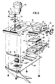
- Fig. 6 illustrates a preferred embodiment of the invention in exploded perspective form of the important components.
- a casing cover 50 is shown upon which the motor 52 and its gear drive 54 as well as the light source housing are mounted.
- the fixed magnification lens system is illustrated at 58 having its adjustment thread 60 adapted to be received in the internal thread 62 of the frame member 64 and shown associated with the collar 66 and lever 68 which may be manually swung to effect the desired focus of the lens system 58.
- the entire assembly of Fig. 6 may be enclosed within the housing H and the plate portion 70 is affixed to the underside of the cover 50 to define a pocket within which the unit 72 (Fig. 6) is slidably received.
- the unit 72 includes the top plate 74 having the transverse slot 76, the toothed rack 78 of generally L-shape and the L-shape guide 80.
- the top plate also includes the mounting gear 81 for the motor 82 and the drive gear assembly 84 is associated with the motor 82.
- the L-shaped rack assembly 78 and the L-shaped guide 80 are slidably received in the respective transverse slots 86 and 88 in the underside of the cover 50 so that the top plate 74 and components mounted and carried thereon may freely slide back and forth.
- the spur gear 90 of the drive gear assembly 54 engages the rack 78 so that rotation of the motor 52 travels the top plate assembly 74 back and forth, dependent upon the direction of motor rotation, in the direction of the related orthogonal motion.
- the slot 76 in the top plate registers with the opening 92 through which the light source housing 56 projects the light source illumination.
- the bottom plate 94 has a raised peripheral edge 96 engaging against the underside of the top plate 74 to which it is secured and the other orthogonal direction and 98 of the bottom plate 94 defines a slot or opening therewith which slidably receives the map image composite 100 including its support 102.
- the support 102 includes the rack 104 along one edge, as shown, which engages with the spur gear 106 of the gear drive 84 which effects back and forth sliding of the support 102.
- the unit which is the map image composite and its support is freely slidable within the space between the top plate and the bottom plate, the latter having troughs 108 and 110 slidably receiving the corner feet 112 of the unit and reaised table portions 114 providing solid support for the underside of the support 102.
- the mirror M is mounted on the bracket B and the mirror m on the ear E as in Fig. 9 to fold the optical axis as shown and project the magnified image of the appropriate portion of the map image composite through the screen S for display.
- the unit illustrated in Fig. 7 includes the support 120 with its rack 122 and mounting the map image composite comprising the three map images 27, 28 and 29 as in Fig. 4 having the different scales which are to be displayed with fixed magnification.
- the direction of motion corresponding to the direction 7 of X direction is the direction back and forth along which the rack 122 extends, and that the direction along which the rack 78 of the support 74 extends is therefore the Y direction 8
- a common coordinate system for the map images can be defined in terms of the angular rotations of the two motors 52 and 82.
- the intersection of the right-hand edge border and the bottom edge border of the map image 27, would define the x, y values 0,0 of the origin 0 of the common coordinate system, although it will be appreciated that the x and y values 0,0 of such origin are entirely arbitrary and that the 0,0 values were chosen for the purposes of this discussion to make the calculations which follow more simple and straightforward.
- information defining y values the right-hand edge borders of the other map images 28 and 29 must be known.
- the y values of such borders are (28) y1 and (29) y1 .
- the values of the respective scales A, B and C of the map images 27, 28 and 29 must be known.
- the microprocessor of this control system includes the CPU 142 which is programmed to perform different routines in response to certain inputs.
- the following manual inputs effect the stated fuctions:
- the normally open microswitch 124 responds to and is closed by the introduction of the cassette 1 carrying the map image composite microfiche film into the x,y tranport system.
- the map image composite selection switch 126 includes a plurality of buttons 128 corresponding to the number N of map image composites which are contained on the microfiche film and depression of a selected button 128 provides the input to the CPU to generate the + or - outputs to the driver 130 for the motor 24 to rotate it in the proper directions to scroll the microfiche film so that the selected microfiche map image composite N is exposed for display.
- the sensor 132 stores the scrolled x coordinate position (COMP)N 0x of the film in the RAM 144 and the CPU refers to this information which is present in the ROM 146 for each composite N on the film and terminates the drive to the scroll motor 24 when the selected film position (COMP)N 0x is reached.
- the initial reference position is always the origin 0 for the particular map image composite under consideration.
- the operator may move the display to any selected position on the map image 27 by depressing the + or - button on the x control switch 136 and/or the + or - button on the y control switch 138.
- the CPU responds, in each case, by energizing the driver 134 to rotate the motor 18 in the desired direction.
- a shift to another map image 28 or 29 may be effected if desired by depressing the proper one of the shift buttons 148, 150 or 152.
- the map image selector 147 initiates the calculations in the CPU to effect the desired change to switch the display from a particular center point of one map image to the corresponding display center point of the selected map image, with optical light source 140 power source 142 "off" during calculations and movement to the new display position whereupon the light source is returned to power "on".
- the operator may also power the light source of an on by manipulation of the switch 144.
- the ROM 146 contains the necessary information to effect the calculations subsequently required, as has been described for the spatial orientation of the map images in accord with Fig. 7 so that when one of the map selection manual switches 148, 150 or 152 is actuated to send a signal to the CPU, the calculations required to switch between the points P, p or p′ of the map images of the composite in question is performed.
- the calculations are effected in accord with normal programming functions effected by the CPU, involving reading the actual current x and y values from the RAM, addressing the ROM over the line 162 to read the relevant information from the ROM to perform the required calculations, etc.
- the CPU When the calculations are taking place and for a time sufficient for the motors to respond to the commands fed over the lines to the drivers 134 and 135, the CPU energizes the light source 149 of the optical system for a time sufficient to allow the motors 17 and 18 to switch the display to the new, selected map image position.
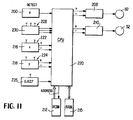
- Figure 11 illustrates the preferred control system for the preferred apparatus as illustrated in Figs. 6-9 wherein the motors 52 an 82 are step motors.
- the microswitch 200 which initiates reference positioning of the microfiche composite by an input signal to the CPU 220.
- the respective drivers 208 and 210 are pulsed by the CPU in the proper direction of drive of the pulse motors 52 and 82 until the reference position of the microfiche is reached.
- the pulse drive to the motor 82 moves the microfiche and its support 100 which has been positioned in the slot between the top and bottom members 74, 94 toward the x reference position while the motor 52 "sucks" this carrier into the grooves 86 and 88 into which it is partially inserted in much the same manner a tape cassette of a VCR is drawn in.
- the motor 52 commences relative y movement between the optical system and the microfiche until the reference point P y value is attained while the motor 82 moves the support 110 with microfiche until the reference point P x value is attained.
- the correct reference point values are read from the ROM 212. It will be understood that the support assembly 100 is initially inserted until the rack 104 engages the gear 106 and that the carrier assembly is inserted until the rack 78 engages the gear 90.
- the ROM 21 contains the information to perform all necessary calculations.
- Additional manual inputs are the + and - pulse controls 216 and 218 for the motor drivers 208 and 210, each having its respective + and - buttons 222 and 224.
- the actual coordinate positions may be written into the RAM.
- the "jump" or switch from one map image to another is effected by depressing the appropriate map selection button 228 on the switch input control 230 and in response to an input therefrom, the CPU commences the requisite calculations to perform the necessary positive or negative pulse commands to the two step motor 52 and 82.
- the current actual x and y positions may be stored in the RAM and updated when the jump or switch has been made.
- An eject switch 226 and its button for control of the motor drivers 208 and 210 initiates the function of reversing the rotations of the motors to eject the carrier until the rack 78 is no longer engaged by the gear 90 and until the rack 104 is no longer engaged by the gear 106.
- the proportion of the scales of three map images is 1:4:16 and the magnification of the optical system is in the order of 25x. It is to be understood that as used herein, and as is believed to be in accord with US convention, the largest map of a composite will have the largest scale so as to display the greatest detail etc., so that if this largest scale is 1:200 000, the above proportions will mean that the next smaller map image of the composite will have a scale of 1:800 000 and the smallest map of the composite will have a scale of 1:3 200 000.
- the microfiche composite film is preferably Cibachrome Micrographic material which is a diapositive material noted for its high resolution.
- the exposures on this material may be made from an enlarged aerial photographic master which may measure 9x9 meters, for example, suitable reduced to the requisite sizes in the proportions of 1:4:16 as noted, on the film material to produce the diapositive composite of the map images.
- a fixed size text may be included on each map image, the fixed text size being large enough to be read at the fixed magnification.
- the small scale map image may contain only text identifying various countries or states in the region denoted on the master
- the next larger scale map image may contain only text identifying various cities, towns or villages within the region which can bee readily seen at the fixed magnification from this larger map image
- the largest scale map image may contain only text identifying streets, etc. which can be readily seen on this largest map image at the fixed magnification.
- the system is mounted for use in an automobile and may derive its power from a cigarette lighter plug.
- the microprocessor is programmed to shut down the light source whenever the system has not been used by the operator for a few minutes, say two minutes.
- the lamp is shut down automatically for a brief period (usually about 2 seconds) while calculations are being performed and the step motors carry out their movement functions.
- the program is such that manual positioning of the step motors is restricted to a center point boundary within the confines of each map image so that the display will not encroach beyond the borders of the map images or cause a dual or overlapped display as has been noted before.
- the system is wired to be "on” whenever the auto ignition is on and the microprocessor program is such that if the ignition is turned off, the eject function will occur.
- the ROM may contain tables designating all of the coordinate positions of each map image so that a corresponding position on one map image may immediately be identified by transposing from the table of that one map image to the table of another map image.
- step motors execute steps of 0,1 mm which are adequate for the purposes intended.
- a rigid support for a microfiche having a rack along one side edge thereof, which is adapted to form part of the map display assembly according to the invention allows the construction of the assembly to be as small as possible. Another advantage is the fact that the rack, being a part which is subject to wear and ageing, is regularly exchanged.
- the fiche may carry additional space on the photographic material. This space may be used for special applications:
- control of such options may take place by means of the x-y-control, i.e. a joystick or other suitable means.
- the two microswitches may be engineered as one single optical switch-signalling (LED/photocell).
- a small part of the fiche (photographic material) is made opaque and a transparant part, such as a cross or the like, is present therein.
- Advantages of this solution use of only one component; optical signalling is very accurate and furthermore: the zero-setting is now directly coupled with the film material, as a result of which in accuraces of the positioning of the film relative to its support is substantially eliminated.
Landscapes
- Physics & Mathematics (AREA)
- General Physics & Mathematics (AREA)
- Instructional Devices (AREA)
- Navigation (AREA)
- Traffic Control Systems (AREA)
- Stereoscopic And Panoramic Photography (AREA)
- Displays For Variable Information Using Movable Means (AREA)
- Processing Or Creating Images (AREA)
Claims (3)
- Kartenabbildungssystem, das eine Mikrofiche-Darstellung von räumlich getrennten ersten (27) und zweiten (28, 29) Kartenbildern des gleichen Gebiets aufweist, die verschiedene Maßstäbe haben, so daß sie individuell mit einer festen Vergrößerung überprüft werden müssen, um Details von entsprechenden Teilen der Kartenbilder (27, 28, 29) zu erkennen, die durch die individuellen Maßstäbe der beiden Kartenbilder und der festen Vergrößerung erlaubt sind,
gekennzeichnet durch
einen im wesentlichen starren Träger (102, 120) für den Mikrofiche (100), der eine Zahnstange (104, 122) längs seinem einen Seitenrand aufweist, und
einen Behälter (72, 94), der einen Schlitz festlegt, um den Träger (102, 120) aufzunehmen, einen durch den Behälter (72, 94) gelagerten Motor und ein Antriebszahnrad (84), das durch den Motor (82) angetrieben wird und in die Zahnstange (104, 122) eingreifen kann, um den Träger (102, 120) in den Behälter (72, 94) entlang einer Bahn (7) zu ziehen und um den Träger nach vorne und zurück entlang der einen Bahn (7) zu befördern, ein Gehäuse (50), das Führungsschlitze (86, 88) aufweist, die sich entlang einer zweiten Bahn (8) orthogonal zu der einen Bahn (7) ausdehnen, wobei der Behälter (72, 94) eine zweite Zahnstange (78), die sich entlang der zweiten Bahn (8) ausdehnt, und Führungen (80) aufweist, die in den Führungsschlitzen (86, 88) aufgenommen sind, wobei das Gehäuse (50) einen zweiten Motor (52) und ein zweites Antriebszahnrad (54) aufweist, das durch den zweiten Motor (52) angetrieben wird und das in die zweite Zahnstange (78) eingreifen kann, um den Behälter (72, 94) in das Gehäuse (50) zu ziehen und um den Behälter (72, 94) nach vorne und zurück entlang der zweiten Bahn (8) zu befördern. - System nach Anspruch 1, bei dem das Kartenbild (28, 29) mit einem kleineren Maßstab klein ist verglichen mit der Größe des anderen Kartenbilds (27) mit einem größeren Maßstab, wobei das System weiter Mittel zum Abbilden eines Teils eines der ausgewählten Kartenbilder mit einer festen Vergröβerung und Mittel zum Umschalten der Abbildung mit fester Vergrößerung aus dem Teil des einen ausgewählten der Kartenbilder auf einen entsprechenden Teil des anderen Kartenbilds aufweist, wobei die Umschaltmittel einen Mikroprozessor (142, 220) aufweisen, der eine Speichereinrichtung (144, 146, 215, 212) zum Speichern der Koordinatenpositionen eines Referenzpunktes des abgebildeten Teils des einen ausgewählten aus den Kartenbildern aufweist, und der so programmiert ist, daß er die entsprechenden Referenzpunktkoordinaten des entsprechenden Teils des anderen Kartenbilds berechnet.
- System nach Anspruch 2, dadurch gekennzeichnet, daß der Motor (18, 82), der durch den Behälter gelagert ist, und der zweite Motor (17, 52) in Abhängigkeit vom Mikroprozessor (142, 220) den Träger orthogonal in bezug auf die Abbildungsmittel bewegen, um ein Umschalten zwischen Abbildungen mit festen Vergrößerungen auszuführen.
Applications Claiming Priority (2)
| Application Number | Priority Date | Filing Date | Title |
|---|---|---|---|
| US17364388A | 1988-03-25 | 1988-03-25 | |
| US173643 | 1988-03-25 |
Publications (3)
| Publication Number | Publication Date |
|---|---|
| EP0334459A2 EP0334459A2 (de) | 1989-09-27 |
| EP0334459A3 EP0334459A3 (de) | 1991-02-06 |
| EP0334459B1 true EP0334459B1 (de) | 1994-09-07 |
Family
ID=22632928
Family Applications (1)
| Application Number | Title | Priority Date | Filing Date |
|---|---|---|---|
| EP89200740A Expired - Lifetime EP0334459B1 (de) | 1988-03-25 | 1989-03-22 | Vorrichtung zur Projektion von Karteninformation |
Country Status (4)
| Country | Link |
|---|---|
| EP (1) | EP0334459B1 (de) |
| JP (1) | JPH0623823B2 (de) |
| AT (1) | ATE111238T1 (de) |
| DE (1) | DE68917964T2 (de) |
Cited By (2)
| Publication number | Priority date | Publication date | Assignee | Title |
|---|---|---|---|---|
| AU2006201050B2 (en) * | 2005-03-08 | 2008-12-04 | Northrop Grumman Systems Corporation | Geographic information storage, transmission and display system |
| US7498955B2 (en) | 2005-03-08 | 2009-03-03 | Northrop Grumman Corporation | Geographic image strorage, transmission and display system |
Family Cites Families (4)
| Publication number | Priority date | Publication date | Assignee | Title |
|---|---|---|---|---|
| US3563645A (en) * | 1969-03-13 | 1971-02-16 | Motiva Ltd | Compact microfilm reader |
| US4312577A (en) * | 1979-08-13 | 1982-01-26 | Fitzgerald J Vincent | Motor vehicle map display system |
| GB2070273A (en) * | 1980-02-26 | 1981-09-03 | Ponting I | A map reading device |
| NL8403193A (nl) * | 1984-10-19 | 1986-05-16 | Ambridge Ltd | Inrichting voor het projekteren van dia's met kaartinformatie op meerdere schalen. |
-
1989
- 1989-03-22 DE DE68917964T patent/DE68917964T2/de not_active Expired - Fee Related
- 1989-03-22 EP EP89200740A patent/EP0334459B1/de not_active Expired - Lifetime
- 1989-03-22 AT AT89200740T patent/ATE111238T1/de not_active IP Right Cessation
- 1989-03-27 JP JP1076373A patent/JPH0623823B2/ja not_active Expired - Lifetime
Cited By (3)
| Publication number | Priority date | Publication date | Assignee | Title |
|---|---|---|---|---|
| AU2006201050B2 (en) * | 2005-03-08 | 2008-12-04 | Northrop Grumman Systems Corporation | Geographic information storage, transmission and display system |
| US7495582B2 (en) | 2005-03-08 | 2009-02-24 | Northrop Grumman Corporation | Geographic information storage, transmission and display system |
| US7498955B2 (en) | 2005-03-08 | 2009-03-03 | Northrop Grumman Corporation | Geographic image strorage, transmission and display system |
Also Published As
| Publication number | Publication date |
|---|---|
| JPH0623823B2 (ja) | 1994-03-30 |
| JPH0256537A (ja) | 1990-02-26 |
| ATE111238T1 (de) | 1994-09-15 |
| EP0334459A3 (de) | 1991-02-06 |
| DE68917964T2 (de) | 1995-01-05 |
| EP0334459A2 (de) | 1989-09-27 |
| DE68917964D1 (de) | 1994-10-13 |
Similar Documents
| Publication | Publication Date | Title |
|---|---|---|
| US4312577A (en) | Motor vehicle map display system | |
| US5090800A (en) | Projector having a liquid crystal display panel | |
| US5024523A (en) | Map projection system | |
| EP0235202B1 (de) | Film-video-wiedergabe-/belichtungsgerät | |
| JPS63500696A (ja) | クロッピング制御を備えたフィルムビデオプレ−ヤ/プリンタ | |
| EP0334459A2 (de) | Vorrichtung zur Projektion von Karteninformation | |
| US4097134A (en) | Projection device | |
| US4549797A (en) | Method and apparatus for positioning microfiche card | |
| US3116661A (en) | Automatic type placement system | |
| US4992828A (en) | Digitizer having selected area designation | |
| US4152722A (en) | Retrieval system | |
| US3320851A (en) | Photographic type placement system | |
| JPS5917577A (ja) | コ−ス誘導装置 | |
| US3748032A (en) | Microform viewer indexing means | |
| JPH07281294A (ja) | 投影装置 | |
| JPS6350713B2 (de) | ||
| JPH0627529A (ja) | 画像処理装置及び記録媒体保持装置 | |
| EP0497145A1 (de) | Hand-Gerät zum Ablesen von Mikrofilmen, insbesondere Mikrofilm-Landkarten oder -Stadtplänen | |
| JPS602923Y2 (ja) | 写真植字機 | |
| US6438326B1 (en) | Apparatus for the exposure of additional information into the film plane of a camera | |
| JPS5924027Y2 (ja) | 文字表示器付観察装置 | |
| JP2888122B2 (ja) | 倍率角度出し装置 | |
| JPH0440745B2 (de) | ||
| JPH06281467A (ja) | 地図表示装置 | |
| JPH06281468A (ja) | 地図表示装置 |
Legal Events
| Date | Code | Title | Description |
|---|---|---|---|
| PUAI | Public reference made under article 153(3) epc to a published international application that has entered the european phase |
Free format text: ORIGINAL CODE: 0009012 |
|
| AK | Designated contracting states |
Kind code of ref document: A2 Designated state(s): AT BE CH DE ES FR GB GR IT LI LU NL SE |
|
| PUAL | Search report despatched |
Free format text: ORIGINAL CODE: 0009013 |
|
| AK | Designated contracting states |
Kind code of ref document: A3 Designated state(s): AT BE CH DE ES FR GB GR IT LI LU NL SE |
|
| RHK1 | Main classification (correction) |
Ipc: G03B 21/11 |
|
| 17P | Request for examination filed |
Effective date: 19910711 |
|
| 17Q | First examination report despatched |
Effective date: 19930713 |
|
| GRAA | (expected) grant |
Free format text: ORIGINAL CODE: 0009210 |
|
| AK | Designated contracting states |
Kind code of ref document: B1 Designated state(s): AT BE CH DE ES FR GB GR IT LI LU NL SE |
|
| PG25 | Lapsed in a contracting state [announced via postgrant information from national office to epo] |
Ref country code: LI Effective date: 19940907 Ref country code: GR Free format text: LAPSE BECAUSE OF FAILURE TO SUBMIT A TRANSLATION OF THE DESCRIPTION OR TO PAY THE FEE WITHIN THE PRESCRIBED TIME-LIMIT Effective date: 19940907 Ref country code: ES Free format text: THE PATENT HAS BEEN ANNULLED BY A DECISION OF A NATIONAL AUTHORITY Effective date: 19940907 Ref country code: CH Effective date: 19940907 Ref country code: AT Effective date: 19940907 |
|
| REF | Corresponds to: |
Ref document number: 111238 Country of ref document: AT Date of ref document: 19940915 Kind code of ref document: T |
|
| ITF | It: translation for a ep patent filed | ||
| REF | Corresponds to: |
Ref document number: 68917964 Country of ref document: DE Date of ref document: 19941013 |
|
| ET | Fr: translation filed | ||
| PG25 | Lapsed in a contracting state [announced via postgrant information from national office to epo] |
Ref country code: SE Effective date: 19941207 |
|
| REG | Reference to a national code |
Ref country code: CH Ref legal event code: PL |
|
| PG25 | Lapsed in a contracting state [announced via postgrant information from national office to epo] |
Ref country code: LU Free format text: LAPSE BECAUSE OF NON-PAYMENT OF DUE FEES Effective date: 19950331 |
|
| PLBE | No opposition filed within time limit |
Free format text: ORIGINAL CODE: 0009261 |
|
| STAA | Information on the status of an ep patent application or granted ep patent |
Free format text: STATUS: NO OPPOSITION FILED WITHIN TIME LIMIT |
|
| 26N | No opposition filed | ||
| PGFP | Annual fee paid to national office [announced via postgrant information from national office to epo] |
Ref country code: GB Payment date: 19970303 Year of fee payment: 9 |
|
| PGFP | Annual fee paid to national office [announced via postgrant information from national office to epo] |
Ref country code: DE Payment date: 19970327 Year of fee payment: 9 |
|
| PGFP | Annual fee paid to national office [announced via postgrant information from national office to epo] |
Ref country code: FR Payment date: 19970328 Year of fee payment: 9 |
|
| PGFP | Annual fee paid to national office [announced via postgrant information from national office to epo] |
Ref country code: NL Payment date: 19970331 Year of fee payment: 9 |
|
| PGFP | Annual fee paid to national office [announced via postgrant information from national office to epo] |
Ref country code: BE Payment date: 19970424 Year of fee payment: 9 |
|
| PG25 | Lapsed in a contracting state [announced via postgrant information from national office to epo] |
Ref country code: GB Free format text: LAPSE BECAUSE OF NON-PAYMENT OF DUE FEES Effective date: 19980322 |
|
| PG25 | Lapsed in a contracting state [announced via postgrant information from national office to epo] |
Ref country code: FR Free format text: THE PATENT HAS BEEN ANNULLED BY A DECISION OF A NATIONAL AUTHORITY Effective date: 19980331 Ref country code: BE Free format text: LAPSE BECAUSE OF NON-PAYMENT OF DUE FEES Effective date: 19980331 |
|
| BERE | Be: lapsed |
Owner name: UNITED OVERSEAS TECHNOLOGY LTD Effective date: 19980331 |
|
| PG25 | Lapsed in a contracting state [announced via postgrant information from national office to epo] |
Ref country code: NL Free format text: LAPSE BECAUSE OF NON-PAYMENT OF DUE FEES Effective date: 19981001 |
|
| GBPC | Gb: european patent ceased through non-payment of renewal fee |
Effective date: 19980322 |
|
| NLV4 | Nl: lapsed or anulled due to non-payment of the annual fee |
Effective date: 19981001 |
|
| PG25 | Lapsed in a contracting state [announced via postgrant information from national office to epo] |
Ref country code: DE Free format text: LAPSE BECAUSE OF NON-PAYMENT OF DUE FEES Effective date: 19981201 |
|
| REG | Reference to a national code |
Ref country code: FR Ref legal event code: ST |
|
| PG25 | Lapsed in a contracting state [announced via postgrant information from national office to epo] |
Ref country code: IT Free format text: LAPSE BECAUSE OF NON-PAYMENT OF DUE FEES Effective date: 20050322 |