EP0347162A2 - Dispositif et méthodes pour la commande de processus de flux de données par des séquences d'instructions générées - Google Patents
Dispositif et méthodes pour la commande de processus de flux de données par des séquences d'instructions générées Download PDFInfo
- Publication number
- EP0347162A2 EP0347162A2 EP89305950A EP89305950A EP0347162A2 EP 0347162 A2 EP0347162 A2 EP 0347162A2 EP 89305950 A EP89305950 A EP 89305950A EP 89305950 A EP89305950 A EP 89305950A EP 0347162 A2 EP0347162 A2 EP 0347162A2
- Authority
- EP
- European Patent Office
- Prior art keywords
- block
- task
- upstream
- connection
- function
- Prior art date
- Legal status (The legal status is an assumption and is not a legal conclusion. Google has not performed a legal analysis and makes no representation as to the accuracy of the status listed.)
- Ceased
Links
Images


Classifications
-
- G—PHYSICS
- G06—COMPUTING OR CALCULATING; COUNTING
- G06F—ELECTRIC DIGITAL DATA PROCESSING
- G06F9/00—Arrangements for program control, e.g. control units
- G06F9/06—Arrangements for program control, e.g. control units using stored programs, i.e. using an internal store of processing equipment to receive or retain programs
- G06F9/46—Multiprogramming arrangements
- G06F9/48—Program initiating; Program switching, e.g. by interrupt
- G06F9/4806—Task transfer initiation or dispatching
- G06F9/4843—Task transfer initiation or dispatching by program, e.g. task dispatcher, supervisor, operating system
- G06F9/4881—Scheduling strategies for dispatcher, e.g. round robin, multi-level priority queues
-
- G—PHYSICS
- G01—MEASURING; TESTING
- G01R—MEASURING ELECTRIC VARIABLES; MEASURING MAGNETIC VARIABLES
- G01R31/00—Arrangements for testing electric properties; Arrangements for locating electric faults; Arrangements for electrical testing characterised by what is being tested not provided for elsewhere
- G01R31/28—Testing of electronic circuits, e.g. by signal tracer
- G01R31/317—Testing of digital circuits
- G01R31/3181—Functional testing
- G01R31/3183—Generation of test inputs, e.g. test vectors, patterns or sequences
- G01R31/318307—Generation of test inputs, e.g. test vectors, patterns or sequences computer-aided, e.g. automatic test program generator [ATPG], program translations, test program debugging
-
- G—PHYSICS
- G01—MEASURING; TESTING
- G01R—MEASURING ELECTRIC VARIABLES; MEASURING MAGNETIC VARIABLES
- G01R31/00—Arrangements for testing electric properties; Arrangements for locating electric faults; Arrangements for electrical testing characterised by what is being tested not provided for elsewhere
- G01R31/28—Testing of electronic circuits, e.g. by signal tracer
- G01R31/317—Testing of digital circuits
- G01R31/3181—Functional testing
- G01R31/319—Tester hardware, i.e. output processing circuits
- G01R31/31903—Tester hardware, i.e. output processing circuits tester configuration
- G01R31/31907—Modular tester, e.g. controlling and coordinating instruments in a bus based architecture
-
- G—PHYSICS
- G06—COMPUTING OR CALCULATING; COUNTING
- G06F—ELECTRIC DIGITAL DATA PROCESSING
- G06F8/00—Arrangements for software engineering
- G06F8/30—Creation or generation of source code
- G06F8/34—Graphical or visual programming
-
- G—PHYSICS
- G06—COMPUTING OR CALCULATING; COUNTING
- G06F—ELECTRIC DIGITAL DATA PROCESSING
- G06F2201/00—Indexing scheme relating to error detection, to error correction, and to monitoring
- G06F2201/865—Monitoring of software
-
- G—PHYSICS
- G06—COMPUTING OR CALCULATING; COUNTING
- G06F—ELECTRIC DIGITAL DATA PROCESSING
- G06F2209/00—Indexing scheme relating to G06F9/00
- G06F2209/48—Indexing scheme relating to G06F9/48
- G06F2209/484—Precedence
Definitions
- the present invention relates to computer con- trof of electronic test and measurement systems and, more particularly, includes methods and apparatus for generating properly interleaved software to implement a system of multi-state resources topologically interconnected to perform a data flow process, and methods of executing the software.
- the invention lies in a similar field to the subject matter of a U.S. patent application entitled BLOCK DIAGRAM EDITOR SYSTEM AND METHOD FOR CONTROLLING ELECTRONIC INSTRUMENTS, U.S. Serial No. 07/007,234. filed January 27, 1987, by Jordan and Stubbs, et al. (corresponding to EP-A-0 295 760; and to that of a U.S. patent application entitled SIGNAL VIEWING INSTRUMENTATION CONTROL SYSTEM, U.S. Serial No. 06 / 935,369, filed November 26, 1986, by Stubbs (corresponding to EP-A-0 278 163).
- Electronic instruments and other devices may conveniently be modeled and controlled with the use of computers.
- interactive control of a measurement instrument may be accomplished through a graphic user interface designed to eliminate direct sequential manipulation of, and obviate detailed familiarity with, the front panel of the instrument.
- Test and measurement systems typically comprise a stimulus device, a device under test (DUT), and a measurement instrument for measuring the response of the DUT to the stimulus.
- a system of this type may conveniently be modeled and controlled using a block diagram editor and electronic instrument control system designed for this purpose, as described in the above- referenced patent applications of Jordan and Stubbs, et al, Serial No. 07/007,234 (EPA No. 88300636.3) and Stubbs, Serial No. 06/935,369.
- Simple topologies are conveniently modeled, in a steady state, using conventional sequential control-flow programming techniques.
- the automated control of individual instruments, or test setups including several instruments or devices usually begins with all physical connections in place, power applied, devices warmed up (i.e., at steady state), and the system generally ready to begin capturing data.
- Data flow systems are characterized in pertinent part by (1) data-activated, asynchronous executions of operations; (2) operands consumed by operators; and (3) the absence of internal state or explicit storage. See Hughes, J. "A High-Level Representation for Implementing Control-Flow Structures in Dataflow Programs," Center for Reliable Computing, Computer Systems Laboratory, Stanford University (CSL Technical Report No. 82-4, May 1982).
- Data flow diagrams can be understood as programs. In these diagrams, blocks represent functions performed on data and connections represent the transmission of data between the functions.
- resources in a data flow diagram represent only computer-based transformations or transmissions of data, a simple rule determines when each can run: upstream resources function before downstream resources. For example, in performing simulations, it may be assumed that all functions are in a steady state, ready to operate in response to inputs.
- the simple rule is inadequate when resources represent external devices that have multiple states such as test instruments, devices-under-test, or physical signal paths.
- a power supply can be off or on.
- a signal path can be made or broken.
- each physical device should be in a quiescent, or safe state when not in use. When the computation or measurement is completed, the device should be returned to the safe state.
- a data flow diagram for instance, that shows "data” (a physical signal) flowing from a power supply to some other physical (e.g., measurement) device
- the power supply must be turned on and remain on while the next (i.e., "downstream") device performs its function.
- dependencies These kinds of relationships among state changes in resources are termed "dependencies.”
- the power supply can be turned off only when all of the downstream functions that depend on the power supply signal have completed their functions.
- the signal path between the power supply and the next device must be made before the signal is applied and broken only after it has been removed.
- execution of a power supply block i.e., function
- a physical connection function also has two related tasks: making the path and breaking it.
- the measurement device such as a multimeter, may require Set-up, such as selecting an appropriate range of measurement, before it properly can "function," i.e., measure the signal.
- This state change from a quiescent or standby mode to an active "measure” mode, is particularly important to protect the measurement device from out-of-range inputs.
- LabVIEW is a graphic, interactive test and measurement instrument control product available from National Instruments. In LabVIEW, “virtual instruments” are created and stored to repeatedly look up and program machine-specific mnemonics for instrument control.
- Signal processing simulation software entitled “Signal Processing Worksystem” provides data paths for control tokens and logic components (e.g., counter, AND, OR, NOT, etc.) to control their flow. (See Signal Processing WorksystemTM Technical Backgrounder, Tektronix CAE Systems Division. 1987). All blocks in SPW, including instrument blocks, can be built with control token inputs and outputs. Programmers must explicitly connect control logic to processing blocks to achieve proper ordering of block functions, as well as make connections representing data flow. Each time a block executes, it behaves according to the pattern of externally-applied control information.
- An object of the present invention is to implicitly order tasks in a computer controlled test and measurement system so that users need not explicitly do so. Another object of the invention is to automatically generate an executable sequence of computer instructions to control a system of resources topologically interconnected and operable . to implement a dataflow process. Yet another object of the present invention is to protect the input circuitry of sensitive measurement instruments used in computer-controlled test and measurement systems. An additional object of the invention is to automatically control a test system so as to ensure that collected data is valid.
- the present invention provides a method of automatically generating a sequence of computer instructions to control a system of resources topologically interconnected and operable to implement a data flow process.
- the resources include blocks and connections.
- the system of resources may conveniently be represented as a block diagram and, preferably, created and manipulated as disclosed in the above-referenced co-pending applications.
- the method includes providing a computer system including prestored code blocks or drivers for implementing the resources.
- a user inputs into the computer system data defining a desired data flow process, the data including an identification of each resource used in the process and the topological interconnection of the resources used in the process.
- the set of tasks associated with a given resource can include no task, or one or more of the tasks: Set-up, Function and Terminate.
- the tasks thus identified are ordered or positioned in accordance with the topological interconnection of the resources and in accordance with a predetermined set of task-positioning rules to form a network of dependencies among the tasks.
- the resulting network is an acyclic graph. It may be represented pictorially, as shown e.g. in FIG. 12.
- the network is used to generate code for controlling the data flow process as more fully explained below.
- the tasks can be suitably ordered by application of a predetermined set of general task-positioning rules.
- the task positioning rules in their simplest form include the following internal task positioning rules:
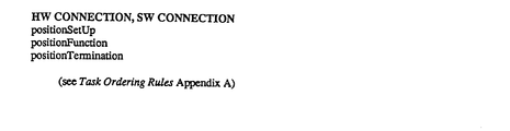
- Appendix A includes a refined set of rules which distinguish among different types of connections (hardware and software) and distinguish among types of inputs (software inputs, hardware inputs and parameter inputs).
- the refined rule list shown in Appendix A subsumes the general rules set forth above.
- the invention further provides for properly interleaving tasks for systems in which one or more resources has multiple inputs and the sequence of applying and/or removing input signals is restricted.
- a device or resource
- input ordering restrictions can be included in the prestored code block for implementing the resource, or may be specified as part of data defining the requirements of a particular block.
- General rules are provided for implementing such restrictions. Application of these rules to the input ordering restrictions defines additional dependencies among tasks, thereby affecting the resulting sorted list of tasks. Ordering rules are provided for enforcing separate restrictions on data application and signal application and/or removal.
- Hierarchic data structures are provided for representing in the computer a block diagram representative of a data flow process.
- the data structure includes an object called BlockDiagram having variables including a list of the block diagram's blocks, a list of the block diagram's connections, and an empty structure called "sortList" to be filled in with an ordered list of the tasks of the block diagram.
- Each block data structure in turn has associated data structures including a list of inputs and outputs and a list of the block's associated tasks. Proceeding down the hierarchy, each task has data structures including a component for identifying the associated block, an object identifying the type of task, a list of predecessor tasks, a reference count, and a list of successor tasks. The last three structures are empty prior to carrying out the task ordering procedure.
- Application of the ordering rules defines a number of dependencies among the tasks. Each such dependency, for example, that a first task precedes a second task, results in the first task being added to the second task's list of predecessors and, conversely, the second task being added to the first task's list of successors.
- the reference count is the number of predecessors. Thus, it is incremented for each predecessor added to the list.
- Code blocks corresponding to the identified tasks can be executed to carry out the process on a physical system modeled by the data flow.
- the preferred embodiment includes screen "animation" such that resources in a data flow diagram are highlighted when their underlying software is executed.
- the list of tasks and their dependencies can be used to link the instructions or drivers together in a proper sequence for executing the tasks.
- the identified tasks are executed using either of two techniques, a linearization technique and / or multiprocessing technique.
- topological sorting In the linearization execution technique, the network of dependencies is partially ordered by a technique called “topological sorting.” (Knuth, Don- ald E., Fundamental Algorithms, Addison-Wesley, 1973, Page 258.) The sorting procedure produces a sequence of lists of tasks called “interior lists.” Each interior list is considered in order. (See text.. below describing FIG. 14.) Within each interior list, the tasks are executed sequentially in any order. Their execution changes the state of the resources. often producing data for their successor tasks. The resulting order of execution is one of many that assure correct execution of the data flow program.
- the corresponding sequence of code may be executed directly to control the data flow process in an integrated system, i.e., one including both a computer programmed with block diagram editor software and data flow-to-sequential conversion software (as disclosed herein) and apparatus for controlling the physical data flow process.
- source code in any convenient language may be generated by known techniques and ported to another computer.
- the generated code may be written to a portable storage medium, such as magnetic tape or floppy disk, for subsequent execution on a target system.
- a target system may be a computer-controlled manufacturing test facility located at a manufacturing site where product (DUT) testing is required.
- the target system may be a relatively simple and inexpensive one, as it need only have the capabilities of interfacing with the physical resources and executing the code. It need have only a single process operating system, for example, MS DOS (TM), to execute the linear code.
- MS DOS MS DOS
- the target system need not have the interactive graphics capabilities of the block diagram editor, nor the other elements included in a system adapted for implementing the present invention.
- the invention includes use of an alternative execution technique on systems having multiprocessing capability, in which linearization is unnecessary.
- the multiprocessing execution may be carried out directly in an integrated multiprocessor system, as above.
- appropriate code may be generated for subsequent execution on a target machine having a multiprocessing operating system.
- each task is made into a standard operating system process.
- these processes are linked using some operating system message-passing system (e.g., semaphores) according to the dependencies.
- some operating system message-passing system e.g., semaphores
- Processes that do not depend on others i.e. those having no predecessors
- the root processes i.e., no predecessors
- APPENDIX A is a list of task-positioning rules incorporated in a preferred embodiment of the invention including Smalltalk-80 (TM) code segments implementing each rule. References such as “R1", “R6” etc. in the FIGURES refer to the corresponding rules set forth in Appendix A. The number following the R refers to the numbering used in Appendix A.
- TM Smalltalk-80
- Appendix B is a list of selected segments of Smalltalk-80 (TM) code incorporated in a preferred embodiment of the invention including comments describing the operation of each code segment.
- TM Smalltalk-80
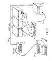
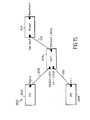
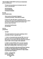
- FIG. 1 depicts a diagram of a system for testing a device-under-test 71 under computer control.
- the diagram shows the layout and interconnection of a computer and programmable test instrumentation system for stimulating the device-under-test (DUT) 71, such as an AM modulator, and detecting and analyzing the response.
- DUT device-under-test
- the system depicted in FIG. 1 includes a computer system 50; protocol converter 64 for connecting the computer system to an interface bus 66 (IEEE-488); three signal generating instruments 68, 70 and 72, all connected to the bus 66; the DUT 71 connected to receive stimuli from the signal generating instruments; and a measurement instrument 74, connected via connection 73 to receive a signal of interest from the DUT and connected to the bus 66 to communicate with the computer system 50.
- the computer system 50 of FIG. 1 includes block diagram editor software for creating and editing block diagrams representing data flow, or simply "data flow diagrams.” This hardware and software are described in detail in Jordan and Stubbs, et al, Serial No. 07/007,234.
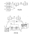
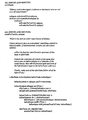
- FIG. 2A illustrates a display screen image generated by the computer system 50 including a data flow diagram corresponding to the test system shown in FIG. 1.
- the diagram is created using the block diagram editor system described in Jordan and Stubbs, et al, Serial No. 07/007,234, and provides the user an interactive means for controlling a hardware system such as that of FIG. 1.
- each instrument or "resource” is represented by a block.
- Blocks 75, 76 and 77 correspond to the signal generators 68, 70 and 72, respectively in FIG. 1.
- Block 78 corresponds to the DUT 71 in FIG. 1
- block 79 represents the measurement instrument 74 in FIG. 1.
- connections 80, 81, 82 and 78A are resources.
- the data flow diagram shown in FIG. 2A shows a set of resources topologically interconnected to model the test system of FIG. 1.
- the resources (signal generator blocks 75, 76 and 77) generate data to stimulate the DUT block 78: transmit data (connections 80, 81, 82 and 78A); respond to data (DUT block 78); and sense data (measurement instrument block 79).
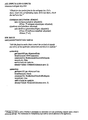
- FIG. 2B shows the relationship between three of the physical elements of the test system of FIG. 1. and its virtual implementation as a network of blocks and connections in a system according to the present invention.
- the physical DUT 71 is represented by block 78.
- the physical measurement instrument 74 is represented by block 79.
- the computer system provides the user interactive control of the physical devices, over the GPIB bus 66, through the medium of the blocks and connections.
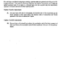
- Tasks are operations which change the state of a resource or cause it to generate data. Though any number of task types may be identified, three types or classes of tasks are sufficient for common instrument control situations. These three tasks are denominated “Set-up.” “Function,” and “Terminate.” The classes are defined generally as follows:
- a Set-up task uses parameters to prepare a resource to function, placing it in a state ready to produce an output, or ready for the arrival of data (including physical signals).
- blocks representing measurement devices usually have Set-up tasks.
- a Function task produces output data, transforms input data making output data available, or consumes input data to produce some external effect, for example, producing a display, writing to a file, or printing a report. Stated differently, the function task drives a resource from a quiescent, standby state to an active, functioning state.
- a resource might not have a function task where it has no way of controlling its output. This is the case where an input signal is applied and an output signal is immediately present, as across a resistor.
- Terminate task makes an output physical signal unavailable, disconnects a resource from an input signal, or returns a resource to a quiescent, ready, or safe state.
- resources representing external, physical devices often require a combination of tasks. In effect, these tasks drive the physical device through state transitions taking it from a quiescent or safe state to an active, functioning state, and then back. Other types of resources may require no tasks at all because they have but one state.
- An example is a passive electronic component such as a resistor.
- Typical task combinations and representative examples include:
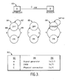
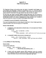
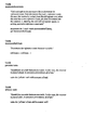
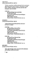
- FIG. 3 depicts a second illustrative data flow diagram 83 consisting of Stimulus Block A connected to a Sensor B by a physical Connection C.
- the stimulus A such as a signal generator, may be in either of two states, ON or OFF. This is represented by a state diagram 84 shown below block A in FIG. 3, in which the letter S stands for Set-up, F for Function and T for Terminate.
- Block A accordingly has associated with it a set of tasks including Set-up, Function and Terminate.
- Set-up generally is conducted with the device in an off or quiescent state and does not change that state, as indicated by arrow 87.
- Set-up may include setting parameters such as the output voltage swing or waveform to be generated. In test systems such as that described in Jordan, et al, these parameters may be set through a graphic interface.
- Block A's Function task indicated by arrow 89, takes the signal generator from the OFF state to the ON state, i.e. an active state where the signal generated by A is present at its output.
- the Terminate task indicated by arrow 88, changes the device from the ON state to the OFF state.
- the hardware connection C has two states, it simply is made or broken. It may be considered ON when the connection is made, i.e. an electrically conductive path is established between its input and its output, and OFF when the connection is broken.
- the Set-up task changes the state of connection from OFF to ON and the Terminate tasks changes it from ON to OFF again. These state changes are illustrated in state diagram 85 in FIG. 3.
- the senor B e.g., a measurement device
- the sensor B has a standby or quiescent state and a functioning or active state. Its parameters are set up during the standby or quiescent state. In the active state, it measures the signal at its input and generates data. This sequence is important to avoid abusing the instrument by changing measurement parameters while an upstream device is applying a signal.
- the Function task changes it to ON or active state and the Terminate task returns it to standby state. These state changes are indicated in state diagram 86, shown below the sensor B in FIG. 3.
- Interleaving refers to an ordering among all of the tasks associated with a data flow system (for example, among the 7 tasks shown in Table 90 in FIG. 3). The interleaving is accomplished in accordance with the internal task-positioning rules set forth above and, additionally, for each resource relative to another in accordance with the following general external task-positioning rules:
- the stimulus (Block A) is a signal generator and that the sensor (Block B) is a digital multimeter (DMM).
- the signal generator is a physical resource having associated tasks Set-up; Function and Terminate.
- the DMM is a physical resource having associated tasks Set-up and Function.
- the connection C is a physical connection, having associated tasks Set-up and Terminate.
- Resource table 90 in FIG. 3 summarizes the three resources A, B and C comprising the data flow diagram 83 and their respective tasks.
- each resource is listed in a first column 92
- each resource is identified in a second column 94
- the respective tasks associated with each resource are abbreviated in a third column 96.
- column 96 (and in FIGS. 3-7), the abbreviation “s” stands for Set-up, “f” stands for Function, and "t” refers to Terminate.
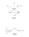
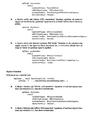
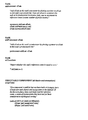
- FIG. 4 the collection of tasks to be interleaved to implement the data flow of FIG. 3 are shown randomly arranged on the page. Lines are drawn between the tasks showing dependencies in accordance with the general rules set forth above.
- the solid lines are dependencies arising from general external positioning rules.
- the dashed lines show examples of dependencies arising from the general internal positioning rules.
- the dependency lines terminate in arrowheads which indicate the sequence of control flow prescribed by the rules.
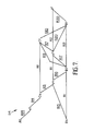
- FIG. 5 shows a sorted, directed graph of the tasks and dependencies of FIG. 4 in which control flows from left to right. It illustrates pictorially a partially ordered list of tasks for execution, discussed below. The tasks are properly interleaved to protect the test instrument and produce valid measurement data.
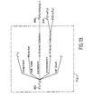
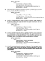
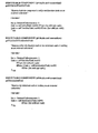
- FIG. 6 depicts a third data flow diagram 110 and corresponding resource table 112.
- the data flow diagram 110 includes three resource blocks, labeled A, B, and C respectively, and interconnections x and y.
- the resource table 112 sets forth the specific nature of the resources comprising the diagram and their respective tasks, shown within parentheses. Note the presence of a software connection x between resource A and a first input 116 to resource C. The letter p adjacent the input 116 designates a parameter input. A hardware or physical connection y connects resource B to resource C.
- Resource B may be a measurement or data acquisition instrument, such as a programmable multimeter.
- the multimeter has two inputs, the signal to be measured, produced by resource B and provided to the multimeter via physical connection y, and a parameter input which is provided over software connection X from a driver A in the computer system.
- the parameter might be, for example, range or sensitivity selection.
- C is downstream of both resources A and B.
- rule 4 of the refined rule list applies to this system. It provides, "A block's Set-up task follows software connections' Function [tasks] upstream of parameter inputs.”
- the directed graph 114 includes the tasks of data flow diagram 110 properly ordered in accordance with the refined rule list.
- the rule number which dictates each dependency is indicated with an R adjacent the line indicating that dependency.
- a I A's Function, i.e., providing the parameter to Set-up C
- C s Set-up in accordance with the quoted rule.
- all positioning rules are applied (if they can be applied) to every data flow diagram. This results in redundant dependencies on occasion, but they cause no harm in practice and allowing them obviates substantial additional code necessary to identify and remove such redundant dependencies.
- the DAG 114 illustrates the resulting partially ordered list of tasks.
- the code segments corresponding to the tasks are linked sequentially in accordance with the list.
- the resulting code may be written to a file or complied for execution.
- FIGS. 8-20 include illustrative data structures for implementing the present invention in an object-oriented programming environment. The description proceeds through the use of two illustrative data flow block diagrams, shown in FIG. 8 and FIG. 15.
- FIGS. 8-14 illustrate a preferred implementation of the invention in a simple software example by means of hierarchic data structures.
- FIGS. 15-21 extend the principles of the invention to input ordering in an example of a test system.
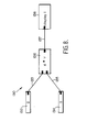
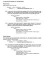
- a fourth illustrative data flow block diagram 130 shows a data flow system which may be implemented in software exclusively. This data flow system multiplies two constants, 2 and 5, and displays the resulting product.
- the diagram consists of blocks 132, 134, 136 and 138 and connections 133, 135 and 137.
- FIG. 9 shows the data structure of the block diagram of FIG. 8.
- angled lines such as line 142 in FIG. 9 illustrate the hierarchic relationship from one data structure to a descendent data structure, generally shown to the right of its parent.
- the data structure 140 of the block diagram includes a list of blocks which is itself an ordered collection, a list of connections which is also an ordered collection and an empty list of sorted tasks, also an ordered collection, here labeled "sortList.”
- SortList In Smalltalk-80o parlance (Smalltalk-80 is a registered trademark of Xerox Corporation), the foregoing three lists or ordered collections are the instance variables of the object BlockDiagram.
- the ordered collection which is a list of blocks contains entries 146 which represent the four blocks shown in FIG. 8.
- the contents of the connections list shown by lines 148 include the three connections shown in the block diagram in FIG. 8.
- an arrow, shown between the names of two blocks, for example, arrow 150 designates a connection between those two blocks with the direction of the arrow indicating the direction of data flow.
- the data structure shown as FIG. 9 is provided by a block diagram editor, similar to that described in Jordan, et al., U.S. Serial No. 07.'007,234.
- the ordered collection 152 designated "sortList.” a list of tasks sorted into an appropriate sequence, will be filled in preparation for execution of the data flow diagram, as further explained below.
- FIG. 10 shows additional detail of a block's data structure.
- the multiply block's (x * y) data structure 160 variables includes a list of the block's tasks, "taskList", and an object containing a list of all of the inputs and outputs of the block, in this case designated alllnputsAndOutput- sObj.
- the taskList in this example, contains only one task, a Function task 162, designated "F(x * y)" in the diagram. Because the multiplier block is implemented in software. Function is the only task associated with it.
- Function task 162 itself has a data structure 170 which includes five . instance variables.
- a component which identifies the block to which the task belongs, in this case the x ⁇ y multiply block.
- a task token here designated “taskToken” is provided which the task sends to its component block at execution time telling it what code block to execute, in this case the code for implementing the multiply block's Function task.
- the task does not itself perform the multiply, but merely signals its parent block, the multiply block, with its task token (#function) to generate an output equal to the product of its inputs.
- Function task 162 data structure includes an ordered collection called “successors" which will be filled with tasks which must follow the present task.
- an ordered collection called “predecessors,” which will be filled with tasks which must precede the present task; and fifth, a variable called "refCount,” which will contain the number of predecessor tasks, are provided.
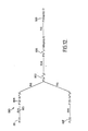
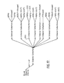
- FIG. 12 shows a network of tasks 180'of the data flow diagram FIG. 8 related by the applicable ordering rules shown in Appendix A.
- the Function task 181 represented by the symbol F(2), is the Function task of the block 132 labeled 2, which represents a constant generator for producing the value 2. That block has no Set-up task, and upon executing its Function task, it generates its output, namely the constant 2.
- the next task downstream in FIG. 12 is the Function task 184 of the connection 133 which connects the constant generator 132 to the multiplier block 136 (FIG. 8).
- the dependency line 185 interconnecting these two blocks in the network is labeled "R14,” signifying the rule (Rule No. 14) listed in Appendix A which requires this dependency.
- Rule 14 "A connection's Function task follows upstream block's Function.”
- FIG. 12 reflects the requirements that the product thus produced be valid and the connection from that product to the display must function (task 188) before the display functions (task 189). This ensures that the information displayed is valid.
- FIG. 13 shows the data structure of the multiplier block Function task 162 after application of the ordering rules.
- the connection's Function task 188 now appears in the ordered collection of successors to the Function task 162 of the multiplier block.
- the connection's Function task 188 is the only task in the list of successors to the m ' ultiplier Function task, as appears in FIG. 12.
- the ordered collection of predecessor tasks now includes the Function task 184 of connection 133, labeled "F(2- >x'y)" and the Function task of connection 135 (FIG. _8), labeled "F(5->x * y)". These tasks must precede the multiplier block Function task 162 in accordance with the dependencies shown in FIG. 12 as prescribed by ordering Rule 6 (APP. A).
- Sorting the tasks to fill in the sortList includes the steps of: collect all tasks whose reference count is zero; add them to the end of the sortList (as a single collection); decrement their successors' reference counts; decrement their own reference counts; and, repeat that sequence of steps.
- the result is that sortList contains a list of collections of partially ordered tasks.
- the dashed box 190 outlines a portion of the figure which corresponds to FIG. 9.
- This figure includes additional data structure showing the contents of the ordered collection called the sortList.
- the sortList is itself a list of ordered collections or "interior lists.”
- the first ordered collection 192 has two entries, the Function task 181 of the constant generator 132 and the Function task 182 of the constant generator 134.
- the sequence of execution of these two tasks is unimportant, hence the sortList is termed "partially ordered.”
- the sequence of execution of the interior lists comprising the sortList is important.
- the ordered collection 192 must be executed prior to execution of the ordered collection 194, and so on down the list.
- FIG. 15 shows a fifth illustrative data flow diagram. depicting a data flow process 200 including instrument resources, i.e., a signal generator 202, a power supply 204, an oscilloscope 214, a device under test (DUT) 212, and connections representing physical data paths 208, 210 and 212 interconnecting the instruments and DUT.
- instrument resources i.e., a signal generator 202, a power supply 204, an oscilloscope 214, a device under test (DUT) 212, and connections representing physical data paths 208, 210 and 212 interconnecting the instruments and DUT.
- DUT device under test
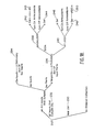
- FIG. 16 shows the network of tasks of the data flow process illustrated in FIG. 15 as related by the applicable ordering rules.
- the rule numbers corresponding to the numbers used in Appendix A, are shown adjacent the respective dependency line in FIG. 16 which is dictated by that rule.
- This graph does not impose any input ordering restrictions on the DUT 206.
- Sorting the information represented by the network of FIG. 16 results in the sortList shown in FIG. 17.
- the third ordered collection in the sortList. at reference legend 220 contains two entries, the Function task 222 of the function generator (block 202) and the Function task 224 of the power supply (block 204). No particular order of execution is imposed on the tasks in collection 220. Accordingly, the function generator and the power supply can begin to function, i.e., produce outputs, in either order, possibly damaging the DUT 206.
- FIG. 18 shows additional portions of the data structure of the DUT block 206.
- the block data structure includes a list of inputs and outputs 232 and a taskList 230.
- the data structure of the list of inputs and outputs includes a dictionary of software inputs 234 and a dictionary of hardware ports 236.
- the dictionary of hardware ports 236 contains entries for each hardware port of the DUT block.
- the signal input 238 includes a set of turn-on antecedents 242 and a set of turn-off antecedents 244.
- the set of turn-on antecedents has a single entry 245, containing a label "#V," a shorthand label signifying voltage, referring to the power supply inputs 240.
- the signal input 238 requires that the power supply input 240 precede it.
- power supply input data structure 240 provides for lists of turn-on antecedents 246 and turn-off antecedents 248.
- the list of turn-off antecedents includes an entry 250 labeled, "#SIGin," a label referring to the signal input 238. This requires that the signal input be removed before turning off or removing the power supply inputs.
- FIG. 20 the block diagram of FIG. 15 is sorted into the sortList shown in FIG. 20 in accordance with all the dependencies shown in the network in FIG. 19. Comparison of this diagram to FIG. 17 shows the effect of the input ordering restrictions.
- the Function task 224 of the power supply here explicitly precedes the Function task 222 of the function generator, whereas as in FIG. 17 their order was indeterminate.
- FIG. 20 includes a sorted list of all of the tasks required to properly set up, operate and terminate operation of the system represented by the block diagram in FIG. 15.
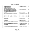
- FIG. 21 shows an example of output code, here in C + + language, for controlling the physical test system represented by the data flow diagram of FIG. 15. This code is generated automatically by operation of the invention, obviating the need for a user or programmer to manually interleave tasks.
- blockDiagram 260 refers to a data structure called blockDiagram, described above with reference to FIGS. 9 and 14.
- Data defining a block diagram representing a data flow, or simply a "data flow diagram,” is entered into the blockDiagram data structure; for example, by block diagram editor software.
- the instruction "BlockDiagram position tasks,” illustrated by dashed box 262, first causes assignment of appropriate tasks to each block and to each connection.
- the instruction “Block position tasks” 266 orders the blocks' tasks by application of internal task order rules, external task order rules and input order rules.
- the resulting ordered list of blocks' tasks is filled into the data structure "taskList.”
- the instruction “Connection position tasks” 270 applies the task order rules to order the connections' tasks. Then, the ordered connections' tasks are appended to taskList.
- the completed taskList is sorted by the "BlockDiagram sort" procedure 276, and the results used to fill in the sortList collection.
- the sortList may be used to control the test system, illustrated by the block labelled "BlockDiagram execute" or the sortList may be used to create a program file that can be written to a disk 278 for subsequent execution on a separate target system.
- the sort procedure may be omitted and the taskList used to control execution.
Landscapes
- Engineering & Computer Science (AREA)
- General Engineering & Computer Science (AREA)
- Software Systems (AREA)
- Physics & Mathematics (AREA)
- General Physics & Mathematics (AREA)
- Theoretical Computer Science (AREA)
- Computer Hardware Design (AREA)
- Stored Programmes (AREA)
- Test And Diagnosis Of Digital Computers (AREA)
- Storage Device Security (AREA)
Applications Claiming Priority (2)
| Application Number | Priority Date | Filing Date | Title |
|---|---|---|---|
| US20664988A | 1988-06-14 | 1988-06-14 | |
| US206649 | 1988-06-14 |
Publications (2)
| Publication Number | Publication Date |
|---|---|
| EP0347162A2 true EP0347162A2 (fr) | 1989-12-20 |
| EP0347162A3 EP0347162A3 (fr) | 1990-09-12 |
Family
ID=22767331
Family Applications (1)
| Application Number | Title | Priority Date | Filing Date |
|---|---|---|---|
| EP19890305950 Ceased EP0347162A3 (fr) | 1988-06-14 | 1989-06-13 | Dispositif et méthodes pour la commande de processus de flux de données par des séquences d'instructions générées |
Country Status (3)
| Country | Link |
|---|---|
| US (1) | US5136705A (fr) |
| EP (1) | EP0347162A3 (fr) |
| JP (1) | JP3079277B2 (fr) |
Cited By (6)
| Publication number | Priority date | Publication date | Assignee | Title |
|---|---|---|---|---|
| EP0552532A3 (en) * | 1992-01-23 | 1995-03-22 | Hewlett Packard Co | A method of testing printed circuit boards |
| WO1995012851A1 (fr) * | 1993-11-03 | 1995-05-11 | Messelektronik Dresden Gmbh | Procede d'essai analogique et/ou numerique d'ensembles electroniques |
| WO1997018512A1 (fr) * | 1995-11-15 | 1997-05-22 | Philips Electronics N.V. | Systeme oriente objet dote d'une specification de modele de classes de donnees persistantes et partagees |
| EP0939321A1 (fr) * | 1998-02-28 | 1999-09-01 | Hewlett-Packard Company | Interface série à haut débit pour un équipement de test et de mesure et système utilisant celle-ci |
| CN1059282C (zh) * | 1996-04-05 | 2000-12-06 | 联华电子股份有限公司 | 具有ram型态保护锁的软件保护方法 |
| WO2002006950A3 (fr) * | 2000-07-18 | 2003-12-31 | Siemens Ag | Procede permettant de produire automatiquement une sequence fonctionnelle de processus, et vehicule correspondant |
Families Citing this family (190)
| Publication number | Priority date | Publication date | Assignee | Title |
|---|---|---|---|---|
| US5481740A (en) * | 1986-04-14 | 1996-01-02 | National Instruments Corporation | Method and apparatus for providing autoprobe features in a graphical data flow diagram |
| US5276885A (en) * | 1991-04-18 | 1994-01-04 | Carnegie Group | Single step mapping in topological order of the queued class and instance frames of a semantic network to a static working memory |
| JPH0546377A (ja) * | 1991-08-08 | 1993-02-26 | Hitachi Ltd | 制御プログラム作成方法及びその作成装置 |
| US5421004A (en) * | 1992-09-24 | 1995-05-30 | International Business Machines Corporation | Hierarchical testing environment |
| US5388261A (en) * | 1992-09-30 | 1995-02-07 | Apple Computer, Inc. | Apparatus and method for handling frame overruns in a digital signal processing system |
| US5390325A (en) * | 1992-12-23 | 1995-02-14 | Taligent, Inc. | Automated testing system |
| US5434965A (en) * | 1992-12-23 | 1995-07-18 | Taligent, Inc. | Balloon help system |
| US5530864A (en) * | 1992-12-23 | 1996-06-25 | Taligent | Command object system for an object-oriented software platform |
| US5315703A (en) * | 1992-12-23 | 1994-05-24 | Taligent, Inc. | Object-oriented notification framework system |
| EP0664025B1 (fr) * | 1992-12-23 | 1997-04-23 | Otlc | Systeme a structure orientee objets |
| JP3793226B2 (ja) * | 1992-12-23 | 2006-07-05 | オブジェクト テクノロジー ライセンシング コーポレイション | アトミック・コマンド・システム |
| US5550563A (en) * | 1992-12-23 | 1996-08-27 | Taligent, Inc. | Interaction framework system |
| US6259446B1 (en) | 1992-12-23 | 2001-07-10 | Object Technology Licensing Corporation | Menu state system |
| US5551055A (en) * | 1992-12-23 | 1996-08-27 | Taligent, Inc. | System for providing locale dependent user interface for presenting control graphic which has different contents or same contents displayed in a predetermined order |
| US5428718A (en) * | 1993-01-22 | 1995-06-27 | Taligent, Inc. | Tessellation system |
| WO1994017480A1 (fr) * | 1993-01-22 | 1994-08-04 | Taligent, Inc. | Systeme souple |
| AU6019094A (en) * | 1993-01-22 | 1994-08-15 | Taligent, Inc. | Business card system |
| JPH08506670A (ja) * | 1993-01-22 | 1996-07-16 | タリジェント インコーポレイテッド | フレキシブル・ネットワーク・システム |
| US5394523A (en) * | 1993-01-22 | 1995-02-28 | Taligent, Inc. | Polymorphic graphic device |
| AU6161594A (en) * | 1993-02-26 | 1994-09-14 | Taligent, Inc. | Collaborative work system |
| US5519862A (en) * | 1993-02-26 | 1996-05-21 | Taligent, Inc. | Concurrent processing apparatus with incremental command objects |
| US5369766A (en) * | 1993-03-25 | 1994-11-29 | Taligent, Inc. | Object-oriented loader system with support for different load formats |
| CA2135517A1 (fr) * | 1993-03-25 | 1994-09-29 | Patrick Delaney Ross | Systeme d'interruption multiniveau |
| US5485373A (en) * | 1993-03-25 | 1996-01-16 | Taligent, Inc. | Language-sensitive text searching system with modified Boyer-Moore process |
| US5459865A (en) * | 1993-04-05 | 1995-10-17 | Taligent Inc. | Runtime loader |
| WO1994023380A1 (fr) * | 1993-04-05 | 1994-10-13 | Taligent, Inc. | Systeme de police pour l'entree de caracteres |
| WO1994023379A1 (fr) * | 1993-04-05 | 1994-10-13 | Taligent, Inc. | Systeme de selection de police de caracteres |
| WO1994025921A1 (fr) * | 1993-04-26 | 1994-11-10 | Taligent, Inc. | Systeme de translitteration de textes |
| US5432948A (en) * | 1993-04-26 | 1995-07-11 | Taligent, Inc. | Object-oriented rule-based text input transliteration system |
| US5544302A (en) * | 1993-06-03 | 1996-08-06 | Taligent, Inc. | Object-oriented framework for creating and using container objects with built-in properties |
| WO1994029803A1 (fr) * | 1993-06-03 | 1994-12-22 | Taligent, Inc. | Systeme a objet representant un emplacement |
| WO1994029791A1 (fr) * | 1993-06-03 | 1994-12-22 | Taligent, Inc. | Systeme de visualisation par objets 'emplacement' |
| US5524190A (en) * | 1993-06-04 | 1996-06-04 | Taligent, Inc. | Command object logging system for restoring documents |
| US5471568A (en) * | 1993-06-30 | 1995-11-28 | Taligent, Inc. | Object-oriented apparatus and method for scan line conversion of graphic edges |
| US5487145A (en) * | 1993-07-09 | 1996-01-23 | Taligent, Inc. | Method and apparatus for compositing display items which minimizes locked drawing areas |
| DE69400870T2 (de) * | 1993-07-19 | 1997-05-15 | Taligent Inc | Dynamisches verknüpfungssystem |
| US6684261B1 (en) | 1993-07-19 | 2004-01-27 | Object Technology Licensing Corporation | Object-oriented operating system |
| US5379432A (en) * | 1993-07-19 | 1995-01-03 | Taligent, Inc. | Object-oriented interface for a procedural operating system |
| US5519867A (en) * | 1993-07-19 | 1996-05-21 | Taligent, Inc. | Object-oriented multitasking system |
| US5404529A (en) * | 1993-07-19 | 1995-04-04 | Taligent, Inc. | Object-oriented interprocess communication system interface for a procedural operating system |
| US5473777A (en) * | 1993-07-19 | 1995-12-05 | Moeller; Christopher P. | Wrapper for enabling an object otented application to maintain virtual memory using procedural function calls |
| US5455951A (en) * | 1993-07-19 | 1995-10-03 | Taligent, Inc. | Method and apparatus for running an object-oriented program on a host computer with a procedural operating system |
| US5471675A (en) * | 1993-07-27 | 1995-11-28 | Taligent, Inc. | Object oriented video framework system |
| DE69406296T2 (de) * | 1993-07-27 | 1998-05-14 | Taligent, Inc., Cupertino, Calif. | Objekorientiertes anzeigesystem |
| US5396626A (en) * | 1993-08-04 | 1995-03-07 | Taligent, Inc. | Object-oriented locator system |
| US5479589A (en) * | 1993-08-04 | 1995-12-26 | Taligent, Inc. | Object-oriented system for selecting a graphic image on a display |
| US5379430A (en) * | 1993-08-04 | 1995-01-03 | Taligent, Inc. | Object-oriented system locator system |
| US5586236A (en) * | 1993-08-11 | 1996-12-17 | Object Technology Licensing Corp. | Universal color look up table and method of generation |
| US5621434A (en) * | 1993-08-11 | 1997-04-15 | Object Technology Licensing Corp. | Cursor manipulation system and method |
| US5566278A (en) * | 1993-08-24 | 1996-10-15 | Taligent, Inc. | Object oriented printing system |
| US5481666A (en) * | 1993-08-25 | 1996-01-02 | Taligent, Inc. | Object-oriented navigation system |
| US5500929A (en) * | 1993-08-30 | 1996-03-19 | Taligent, Inc. | System for browsing a network resource book with tabs attached to pages |
| US5428744A (en) * | 1993-08-30 | 1995-06-27 | Taligent, Inc. | Object-oriented system for building a graphic image on a display |
| WO1995008148A1 (fr) * | 1993-09-13 | 1995-03-23 | Taligent, Inc. | Systeme d'acheminement de donnees multimedia |
| US5388264A (en) * | 1993-09-13 | 1995-02-07 | Taligent, Inc. | Object oriented framework system for routing, editing, and synchronizing MIDI multimedia information using graphically represented connection object |
| AU5989194A (en) * | 1993-09-13 | 1995-04-03 | Taligent, Inc. | Object-oriented audio record/playback system |
| DE69403915T2 (de) | 1993-09-13 | 1998-01-15 | Taligent, Inc., Cupertino, Calif. | Objektorientiertes videosystem |
| US5390138A (en) * | 1993-09-13 | 1995-02-14 | Taligent, Inc. | Object-oriented audio system |
| US5511002A (en) * | 1993-09-13 | 1996-04-23 | Taligent, Inc. | Multimedia player component object system |
| US5583977A (en) * | 1993-10-21 | 1996-12-10 | Taligent, Inc. | Object-oriented curve manipulation system |
| US5522025A (en) * | 1993-10-25 | 1996-05-28 | Taligent, Inc. | Object-oriented window area display system |
| US5455854A (en) * | 1993-10-26 | 1995-10-03 | Taligent, Inc. | Object-oriented telephony system |
| EP0712513B1 (fr) * | 1993-10-29 | 1997-06-04 | Taligent, Inc. | Systeme de logiciel integre pour programme d'edition graphique |
| WO1995012866A1 (fr) * | 1993-11-02 | 1995-05-11 | Taligent, Inc. | Systeme graphique oriente objets |
| US5428722A (en) * | 1993-11-05 | 1995-06-27 | Taligent, Inc. | Object-oriented painter maker |
| US6040838A (en) * | 1993-11-05 | 2000-03-21 | Obejct Technology Licensing Corporation | Graphic state processing |
| US5537526A (en) * | 1993-11-12 | 1996-07-16 | Taugent, Inc. | Method and apparatus for processing a display document utilizing a system level document framework |
| AU6018294A (en) * | 1993-12-02 | 1995-06-19 | Taligent, Inc. | Method and apparatus for displaying hardware dependent graphics in an object-oriented operating system |
| US5594921A (en) * | 1993-12-17 | 1997-01-14 | Object Technology Licensing Corp. | Authentication of users with dynamically configurable protocol stack |
| US5530799A (en) * | 1993-12-17 | 1996-06-25 | Taligent Inc. | Rendering cache in an object oriented system |
| US5548726A (en) * | 1993-12-17 | 1996-08-20 | Taligeni, Inc. | System for activating new service in client server network by reconfiguring the multilayer network protocol stack dynamically within the server node |
| US5515508A (en) * | 1993-12-17 | 1996-05-07 | Taligent, Inc. | Client server system and method of operation including a dynamically configurable protocol stack |
| US5499343A (en) * | 1993-12-17 | 1996-03-12 | Taligent, Inc. | Object-oriented networking system with dynamically configurable communication links |
| US5548723A (en) * | 1993-12-17 | 1996-08-20 | Taligent, Inc. | Object-oriented network protocol configuration system utilizing a dynamically configurable protocol stack |
| AU6702594A (en) * | 1993-12-17 | 1995-07-03 | Taligent, Inc. | Object-oriented distributed communications directory service |
| US5491800A (en) * | 1993-12-20 | 1996-02-13 | Taligent, Inc. | Object-oriented remote procedure call networking system |
| AU6814594A (en) * | 1993-12-21 | 1995-07-10 | Taligent, Inc. | Automatic hardware configuration |
| US5566346A (en) * | 1993-12-21 | 1996-10-15 | Taligent, Inc. | System for constructing hardware device interface software systems independent of operating systems including capability of installing and removing interrupt handlers |
| US5574915A (en) * | 1993-12-21 | 1996-11-12 | Taligent | Object-oriented booting framework |
| US5546595A (en) * | 1993-12-21 | 1996-08-13 | Taligent, Inc. | Object-oriented system using objects representing hardware devices, physical connectors and connections between the physical connectors for configuring a computer |
| US5680624A (en) * | 1993-12-21 | 1997-10-21 | Object Licensing Corporation | Object oriented interrupt system |
| US5548779A (en) * | 1993-12-21 | 1996-08-20 | Taligent | System for providing system services for a device to a client using stack definition and stack description of a stack having top, intermediate, and bottom service objects |
| US5371884A (en) * | 1993-12-21 | 1994-12-06 | Taligent, Inc. | Processor fault recovery system |
| AU7511794A (en) * | 1993-12-22 | 1995-07-10 | Taligent, Inc. | Input methods framework |
| US6179490B1 (en) * | 1993-12-23 | 2001-01-30 | Telefonaktiebolaget Lm Ericsson | Method and apparatus for creating a flowchart using a programmed computer which will automatically result in a structured program |
| US5465362A (en) * | 1993-12-30 | 1995-11-07 | Taligent, Inc. | Object-oriented view-system for displaying information in a windowing environment |
| US5555368A (en) * | 1993-12-30 | 1996-09-10 | Taligent | Object-oriented multi-tasking view framework |
| US5615326A (en) * | 1993-12-30 | 1997-03-25 | Taligent, Inc. | Object-oriented viewing framework having view grouping |
| AU7872494A (en) * | 1993-12-30 | 1995-07-17 | Taligent, Inc. | Object-oriented view coordinate space system |
| US5544301A (en) * | 1993-12-30 | 1996-08-06 | Taligent, Inc. | Object-oriented view layout system |
| US5524199A (en) * | 1993-12-30 | 1996-06-04 | Taligent | Object-oriented view system with background processing of update request |
| WO1995018413A1 (fr) * | 1993-12-30 | 1995-07-06 | Taligent, Inc. | Systeme de hierarchies de vues, oriente objets |
| US5524200A (en) * | 1993-12-30 | 1996-06-04 | Taligent, Inc. | Object-oriented non-rectilinear viewing framework |
| US5832219A (en) | 1994-02-08 | 1998-11-03 | Object Technology Licensing Corp. | Distributed object networking service |
| JPH09510567A (ja) * | 1994-03-21 | 1997-10-21 | オブジェクト テクノロジー ライセンシング コーポレイション | ドキュメント・プロキシィ・フレームワーク |
| US5680563A (en) * | 1994-07-25 | 1997-10-21 | Object Technology Licensing Corporation | Object-oriented operating system enhancement for filtering items in a window |
| US5912666A (en) * | 1994-08-23 | 1999-06-15 | Object Technology Licensing Corp. | Object-oriented global cursor tool |
| US5504892A (en) * | 1994-09-08 | 1996-04-02 | Taligent, Inc. | Extensible object-oriented file system |
| US5519818A (en) * | 1994-09-19 | 1996-05-21 | Taligent, Inc. | Object-oriented graphic picking system |
| CA2202614A1 (fr) * | 1994-10-25 | 1996-05-02 | Taligent, Inc. | Systeme oriente objets destine a gerer des fenetres |
| JPH08241185A (ja) * | 1994-11-03 | 1996-09-17 | Motorola Inc | 統合型試験および測定手段ならびにグラフィカル・ユーザ・インタフェースを採用する方法 |
| US5613122A (en) * | 1994-11-14 | 1997-03-18 | Object Technology Licensing Corp. | Object-oriented operating system |
| US5630131A (en) * | 1994-11-14 | 1997-05-13 | Object Technology Licensing Corp. | Method and apparatus for importing and exporting archive files for a graphical user interface |
| US5652884A (en) * | 1994-11-14 | 1997-07-29 | Object Technology Licensing Corp. | Method and apparatus for dynamic update of an existing object in an object editor |
| US5659735A (en) * | 1994-12-09 | 1997-08-19 | Object Technology Licensing Corp. | Object-oriented system for program version and history database management system for various program components |
| US5553282A (en) * | 1994-12-09 | 1996-09-03 | Taligent, Inc. | Software project history database and method of operation |
| US5752245A (en) * | 1994-12-09 | 1998-05-12 | Object Technology Licensing Corporation | Object-oriented system for configuration history management with a project workspace and project history database for draft identification |
| US5729748A (en) * | 1995-04-03 | 1998-03-17 | Microsoft Corporation | Call template builder and method |
| US5909595A (en) * | 1995-05-15 | 1999-06-01 | Nvidia Corporation | Method of controlling I/O routing by setting connecting context for utilizing I/O processing elements within a computer system to produce multimedia effects |
| US5713045A (en) * | 1995-06-29 | 1998-01-27 | Object Technology Licensing Corporation | System for processing user events with input device entity associated with event producer which further links communication from event consumer to the event producer |
| US5737498A (en) * | 1995-07-11 | 1998-04-07 | Beckman Instruments, Inc. | Process automation method and apparatus |
| US5954792A (en) * | 1996-12-30 | 1999-09-21 | Cadence Design Systems, Inc. | Method for schedule validation of embedded systems |
| US6408429B1 (en) | 1997-01-17 | 2002-06-18 | Cognex Corporation | Machine vision system for identifying and assessing features of an article |
| CN1266510A (zh) * | 1997-04-04 | 2000-09-13 | 弗雷德·史蒂文·伊索姆 | 根据方向场中的任务对象的相对空间位置对计算机控制的任务排序的方法 |
| US6272674B1 (en) * | 1998-12-14 | 2001-08-07 | Nortel Networks Limited | Method and apparatus for loading a Java application program |
| US6389587B1 (en) * | 1999-02-04 | 2002-05-14 | Sun Microsystems, Inc. | User interface for developing and executing data flow programs and methods, apparatus, and articles of manufacture for optimizing the execution of data flow programs |
| US6449711B1 (en) | 1999-02-04 | 2002-09-10 | Sun Microsystems, Inc. | Method, apparatus, and article of manufacture for developing and executing data flow programs |
| US6687834B1 (en) | 2000-04-14 | 2004-02-03 | International Business Machines Corporation | Data processing system, method and program for generating a job within an automated test environment |
| US6959433B1 (en) | 2000-04-14 | 2005-10-25 | International Business Machines Corporation | Data processing system, method, and program for automatically testing software applications |
| US6675338B1 (en) | 2000-08-09 | 2004-01-06 | Sun Microsystems, Inc. | Internally generated vectors for burnin system |
| US6675372B1 (en) | 2000-10-31 | 2004-01-06 | Sun Microsystems, Inc. | Counting speculative and non-speculative events |
| US6879926B2 (en) | 2001-06-29 | 2005-04-12 | National Instruments Corporation | Measurement system software architecture for easily creating high-performance measurement applications |
| US7162387B2 (en) * | 2001-06-29 | 2007-01-09 | National Instruments Corporation | Measurement system graphical user interface for easily configuring measurement applications |
| US20030005153A1 (en) * | 2001-06-29 | 2003-01-02 | National Instruments Corporation | Dynamic routing for a measurement system |
| US20030005154A1 (en) * | 2001-06-29 | 2003-01-02 | Thurman Robert W. | Shared routing in a measurement system |
| US7969431B2 (en) | 2001-06-29 | 2011-06-28 | National Instruments Corporation | Graphical program node for generating a measurement program |
| US20030004673A1 (en) * | 2001-06-29 | 2003-01-02 | Thurman Robert W. | Routing with signal modifiers in a measurement system |
| US20030004672A1 (en) * | 2001-06-29 | 2003-01-02 | National Instruments Corporation | Meta-routing tool for a measurement system |
| US7984423B2 (en) * | 2001-08-14 | 2011-07-19 | National Instruments Corporation | Configuration diagram which displays a configuration of a system |
| US7302675B2 (en) * | 2001-08-14 | 2007-11-27 | National Instruments Corporation | System and method for analyzing a graphical program using debugging graphical programs |
| US8290762B2 (en) * | 2001-08-14 | 2012-10-16 | National Instruments Corporation | Graphically configuring program invocation relationships by creating or modifying links among program icons in a configuration diagram |
| US7594220B2 (en) * | 2001-08-14 | 2009-09-22 | National Instruments Corporation | Configuration diagram with context sensitive connectivity |
| US7043393B2 (en) * | 2001-08-15 | 2006-05-09 | National Instruments Corporation | System and method for online specification of measurement hardware |
| US6889172B2 (en) * | 2001-08-15 | 2005-05-03 | National Instruments Corporation | Network-based system for configuring a measurement system using software programs generated based on a user specification |
| US7013232B2 (en) * | 2001-08-15 | 2006-03-14 | National Insurance Corporation | Network-based system for configuring a measurement system using configuration information generated based on a user specification |
| US7050923B2 (en) * | 2001-08-15 | 2006-05-23 | National Instruments Corporation | Network-based system for configuring a measurement system using configuration information generated based on a user specification |
| US20030060509A1 (en) * | 2001-08-24 | 2003-03-27 | Elswyk Mary Van | Products containing highly unsaturated fatty acids for use by women and their children during stages of preconception, pregnancy and lactation/post-partum |
| US7512931B2 (en) * | 2001-11-13 | 2009-03-31 | National Instruments Corporation | Graphical program nodes for implementing a measurement state model |
| US7089141B2 (en) * | 2001-11-13 | 2006-08-08 | National Instruments Corporation | Measurement system which uses a state model |
| US20040031019A1 (en) * | 2002-05-20 | 2004-02-12 | Richard Lamanna | Debugger for a graphical programming environment |
| US7890868B2 (en) * | 2002-08-13 | 2011-02-15 | National Instruments Corporation | Selecting a connectable element of a hardware device in a measurement system |
| US7356774B2 (en) * | 2002-08-13 | 2008-04-08 | National Instruments Corporation | Grouping components of a measurement system |
| US7219306B2 (en) * | 2002-08-13 | 2007-05-15 | National Instruments Corporation | Representing unspecified information in a measurement system |
| US7761802B2 (en) * | 2002-08-13 | 2010-07-20 | National Instruments Corporation | Expanding and collapsing components in a measurement system diagram |
| US7042469B2 (en) * | 2002-08-13 | 2006-05-09 | National Instruments Corporation | Multiple views for a measurement system diagram |
| US20040034496A1 (en) * | 2002-08-13 | 2004-02-19 | Correll Jeffrey N. | Displaying functionality of a hardware device in a measurement system |
| US7484200B2 (en) * | 2002-08-14 | 2009-01-27 | National Instruments Corporation | Automatically analyzing and modifying a graphical program |
| US7765532B2 (en) * | 2002-10-22 | 2010-07-27 | Oracle America, Inc. | Inducing concurrency in software code |
| US7222218B2 (en) * | 2002-10-22 | 2007-05-22 | Sun Microsystems, Inc. | System and method for goal-based scheduling of blocks of code for concurrent execution |
| US7346902B2 (en) * | 2002-10-22 | 2008-03-18 | Sun Microsystems, Inc. | System and method for block-based concurrentization of software code |
| US7603664B2 (en) * | 2002-10-22 | 2009-10-13 | Sun Microsystems, Inc. | System and method for marking software code |
| US8220058B2 (en) * | 2003-09-25 | 2012-07-10 | Oracle America, Inc. | Rendering and encryption engine for application program obfuscation |
| US7353499B2 (en) | 2003-09-25 | 2008-04-01 | Sun Microsystems, Inc. | Multiple instruction dispatch tables for application program obfuscation |
| US7363620B2 (en) * | 2003-09-25 | 2008-04-22 | Sun Microsystems, Inc. | Non-linear execution of application program instructions for application program obfuscation |
| US7415618B2 (en) * | 2003-09-25 | 2008-08-19 | Sun Microsystems, Inc. | Permutation of opcode values for application program obfuscation |
| US7424620B2 (en) * | 2003-09-25 | 2008-09-09 | Sun Microsystems, Inc. | Interleaved data and instruction streams for application program obfuscation |
| US20050069138A1 (en) * | 2003-09-25 | 2005-03-31 | Sun Microsystems, Inc., A Delaware Corporation | Application program obfuscation |
| US7054700B2 (en) * | 2003-11-17 | 2006-05-30 | Lenovo Pte. Ltd. | Method and system for efficient order processing in a manufacturing environment |
| US7284120B2 (en) | 2003-11-17 | 2007-10-16 | Lenovo (Singapore) Pte. Ltd. | Method and system for allowing a system under test (SUT) to boot a plurality of operating systems without a need for local media |
| US20050240831A1 (en) * | 2004-03-31 | 2005-10-27 | Balkman William D | Universal controller and graphical user interface |
| TW200535602A (en) * | 2004-04-16 | 2005-11-01 | Hon Hai Prec Ind Co Ltd | A system and method for testing motherboards automatically |
| GB2422204A (en) * | 2005-01-12 | 2006-07-19 | Advanced Testing Technologies | Obsolescence mitigation in automatic test equipment |
| US8484618B2 (en) | 2005-01-12 | 2013-07-09 | Advanced Testing Technologies, Inc. | Test program set obsolescence mitigation through software and automatic test equipment processes |
| US20060168555A1 (en) * | 2005-01-21 | 2006-07-27 | Represas Ferrao Lucio E | Software development system and method |
| US20060168577A1 (en) * | 2005-01-21 | 2006-07-27 | Melo Antonio A V | Software development system and method |
| US7735062B2 (en) * | 2005-01-21 | 2010-06-08 | Outsystems—Software Em Rede, S.A. | Software development system and method |
| US7543200B2 (en) * | 2005-02-17 | 2009-06-02 | Advantest Corporation | Method and system for scheduling tests in a parallel test system |
| JP4728020B2 (ja) * | 2005-03-17 | 2011-07-20 | 日立オートモティブシステムズ株式会社 | 車両制御用ソフトウェア及び車両制御装置 |
| GB2425622A (en) * | 2005-04-27 | 2006-11-01 | Ncapsa Ltd | Programming real-time systems using data flow diagrams |
| US7359824B2 (en) * | 2005-06-29 | 2008-04-15 | International Business Machines Corporation | Systems and methods for a distributed execution environment with per-command environment management |
| US7853926B2 (en) * | 2005-11-21 | 2010-12-14 | International Business Machines Corporation | Automated context-sensitive operating system switch |
| US8359585B1 (en) | 2007-01-18 | 2013-01-22 | Advanced Testing Technologies, Inc. | Instrumentation ATS/TPS mitigation utilizing I/O data stream |
| US20110185353A1 (en) * | 2010-01-27 | 2011-07-28 | Jack Matthew | Mitigating Problems Arising From Incompatible Software |
| US20110225524A1 (en) * | 2010-03-10 | 2011-09-15 | Cifra Christopher G | Multi-Touch Editing in a Graphical Programming Language |
| GB2484967B (en) * | 2010-10-28 | 2017-01-04 | Fujitsu Ltd | Method, apparatus, and program for the discovery of resources in a computing environment |
| US8713482B2 (en) | 2011-07-28 | 2014-04-29 | National Instruments Corporation | Gestures for presentation of different views of a system diagram |
| US8782525B2 (en) | 2011-07-28 | 2014-07-15 | National Insturments Corporation | Displaying physical signal routing in a diagram of a system |
| EP2852473B1 (fr) | 2012-05-23 | 2020-12-23 | Saint-Gobain Ceramics & Plastics Inc. | Particules abrasives mises en forme et leurs procédés de formation |
| KR101889698B1 (ko) | 2013-09-30 | 2018-08-21 | 생-고뱅 세라믹스 앤드 플라스틱스, 인코포레이티드 | 형상화 연마입자 및 이의 형성 방법 |
| CN105793818B (zh) * | 2013-12-06 | 2019-09-17 | 起元科技有限公司 | 源代码翻译 |
| US9747112B2 (en) | 2014-09-02 | 2017-08-29 | Ab Initio Technology, Llc | Managing invocation of tasks |
| WO2016036826A1 (fr) | 2014-09-02 | 2016-03-10 | Ab Initio Technology Llc | Compilation de spécifications de programme basées sur un graphique |
| CA2959627C (fr) * | 2014-09-02 | 2020-06-16 | Ab Initio Technology Llc | Execution de specifications de programme a base de graphes |
| US10235868B2 (en) * | 2014-09-29 | 2019-03-19 | National Instruments Corporation | Embedded shared logical instrument |
| US10055327B2 (en) | 2014-09-30 | 2018-08-21 | International Business Machines Corporation | Evaluating fairness in devices under test |
| US9914864B2 (en) | 2014-12-23 | 2018-03-13 | Saint-Gobain Ceramics & Plastics, Inc. | Shaped abrasive particles and method of forming same |
| TWI634200B (zh) | 2015-03-31 | 2018-09-01 | 聖高拜磨料有限公司 | 固定磨料物品及其形成方法 |
| US10759024B2 (en) | 2017-01-31 | 2020-09-01 | Saint-Gobain Ceramics & Plastics, Inc. | Abrasive article including shaped abrasive particles |
| US10865148B2 (en) | 2017-06-21 | 2020-12-15 | Saint-Gobain Ceramics & Plastics, Inc. | Particulate materials and methods of forming same |
| US11620605B2 (en) | 2019-10-09 | 2023-04-04 | International Business Machines Corporation | Summarizing business process models |
Family Cites Families (9)
| Publication number | Priority date | Publication date | Assignee | Title |
|---|---|---|---|---|
| JPS58166498A (ja) * | 1982-03-27 | 1983-10-01 | 富士通電装株式会社 | 自動測定装置 |
| US4595981A (en) * | 1984-03-05 | 1986-06-17 | At&T Bell Laboratories | Method of testing interfaces between computer program modules |
| US4742467A (en) * | 1984-05-04 | 1988-05-03 | Analysts International Corporation | Automated programming system for machine creation of applications program source code from non-procedural terminal input |
| AU5506286A (en) * | 1985-04-08 | 1986-10-16 | American Telephone And Telegraph Company | Program generator |
| JPS62128335A (ja) * | 1985-11-30 | 1987-06-10 | Toshiba Corp | プログラム作成装置 |
| JPS62197826A (ja) * | 1986-02-25 | 1987-09-01 | Hitachi Ltd | システムフロ−仕様生成方式 |
| CA1268557A (fr) * | 1986-04-01 | 1990-05-01 | Mikio Tomioka | Methode d'affichage des circonstances d'execution d'un programme et appareil utilisant cette methode |
| US4812996A (en) * | 1986-11-26 | 1989-03-14 | Tektronix, Inc. | Signal viewing instrumentation control system |
| US4868785A (en) * | 1987-01-27 | 1989-09-19 | Tektronix, Inc. | Block diagram editor system and method for controlling electronic instruments |
-
1989
- 1989-06-13 EP EP19890305950 patent/EP0347162A3/fr not_active Ceased
- 1989-06-14 JP JP01152034A patent/JP3079277B2/ja not_active Expired - Lifetime
-
1991
- 1991-06-10 US US07/711,723 patent/US5136705A/en not_active Expired - Lifetime
Non-Patent Citations (3)
| Title |
|---|
| ELECTRONIC DESIGN, vol. 35, no. 2, 22nd January 1987, pages 111-114, Hasbrouck Heights, NJ, US; L.L. MAZZUCCHELLI: "Modified structured analysis speeds real-time programming" * |
| PROCEEDINGS OF THE THIRD CONFERENCE ON ARTIFICIAL INTELLIGENCE APPLICATIONS, Orlando, Florida, 23rd-27th February 1987, pages 134-139, IEEE, New York, US; A. CRUISE et al.: "YES/L1: Integrating rule-based, procedural, and real-time programming for industrial applications" * |
| WESCON'87, CONFERENCE RECORD, vol. 31, no. 2/4, 1987, pages 1-14, Los Angeles, CA, US; K. MOORE et al.: "Instrument system software methodology and architecture" * |
Cited By (6)
| Publication number | Priority date | Publication date | Assignee | Title |
|---|---|---|---|---|
| EP0552532A3 (en) * | 1992-01-23 | 1995-03-22 | Hewlett Packard Co | A method of testing printed circuit boards |
| WO1995012851A1 (fr) * | 1993-11-03 | 1995-05-11 | Messelektronik Dresden Gmbh | Procede d'essai analogique et/ou numerique d'ensembles electroniques |
| WO1997018512A1 (fr) * | 1995-11-15 | 1997-05-22 | Philips Electronics N.V. | Systeme oriente objet dote d'une specification de modele de classes de donnees persistantes et partagees |
| CN1059282C (zh) * | 1996-04-05 | 2000-12-06 | 联华电子股份有限公司 | 具有ram型态保护锁的软件保护方法 |
| EP0939321A1 (fr) * | 1998-02-28 | 1999-09-01 | Hewlett-Packard Company | Interface série à haut débit pour un équipement de test et de mesure et système utilisant celle-ci |
| WO2002006950A3 (fr) * | 2000-07-18 | 2003-12-31 | Siemens Ag | Procede permettant de produire automatiquement une sequence fonctionnelle de processus, et vehicule correspondant |
Also Published As
| Publication number | Publication date |
|---|---|
| JPH0244421A (ja) | 1990-02-14 |
| JP3079277B2 (ja) | 2000-08-21 |
| EP0347162A3 (fr) | 1990-09-12 |
| US5136705A (en) | 1992-08-04 |
Similar Documents
| Publication | Publication Date | Title |
|---|---|---|
| US5136705A (en) | Method of generating instruction sequences for controlling data flow processes | |
| Bitter et al. | LabVIEW: Advanced programming techniques | |
| US5051938A (en) | Simulation of selected logic circuit designs | |
| US8281242B2 (en) | Editable data tooltips | |
| Ashenden | The designer's guide to VHDL | |
| EP0153445B1 (fr) | Méthode pour simuler l'opération de système de dispositifs à circuits statiques et dynamiques | |
| US6212650B1 (en) | Interactive dubug tool for programmable circuits | |
| EP1004085B1 (fr) | Conversion de programmes graphiques en realisations materielles et systeme correspondant | |
| EP0988558B1 (fr) | Logiciel de systeme de test automatique facile a utiliser et de faible cout | |
| US7134081B2 (en) | Method and apparatus for controlling an instrumentation system | |
| US5251159A (en) | Circuit simulation interface methods | |
| WO1985002033A1 (fr) | Appareil et procede de simulation pour systeme numerique | |
| WO1999027473A1 (fr) | Configuration reseau de circuits programmables | |
| Bending | Hitest: A knowledge-based test generation system | |
| Szygenda | Modeling and digital simulation for design verification and diagnosis | |
| Fuchs et al. | Workstation-based logic animation and microarchitecture emulation for teaching introduction to computer engineering | |
| Reid et al. | Implementing a graphical user interface for SystemC | |
| Jayakumar et al. | Simulaton of Microprocessor Emulation Using GASP-PL/I | |
| WO1991020032A1 (fr) | Systeme de logiciels a maintenance et developpement integres | |
| Rivas-Villegas et al. | Graphical framework for automatic generation of custom UVM testbenches in SystemVerilog applied for the validation of a SerDes DUT | |
| Kelly | MultiSimPC: a multilevel logic simulator for microcomputers | |
| O'Neill | An improved chip-level test generation algorithm | |
| Nimmo et al. | A VLSI design strategy for graphics | |
| Vidlak | User-object interfaces in an object-oriented discrete event simulation environment | |
| Christley | Thick film substrate (Micropackage) design utilizing interactive Computer Aided Design systems |
Legal Events
| Date | Code | Title | Description |
|---|---|---|---|
| PUAI | Public reference made under article 153(3) epc to a published international application that has entered the european phase |
Free format text: ORIGINAL CODE: 0009012 |
|
| AK | Designated contracting states |
Kind code of ref document: A2 Designated state(s): DE FR GB NL |
|
| PUAL | Search report despatched |
Free format text: ORIGINAL CODE: 0009013 |
|
| AK | Designated contracting states |
Kind code of ref document: A3 Designated state(s): DE FR GB NL |
|
| 17P | Request for examination filed |
Effective date: 19910306 |
|
| RAP1 | Party data changed (applicant data changed or rights of an application transferred) |
Owner name: TEKTRONIX, INC. |
|
| 17Q | First examination report despatched |
Effective date: 19931022 |
|
| STAA | Information on the status of an ep patent application or granted ep patent |
Free format text: STATUS: THE APPLICATION HAS BEEN REFUSED |
|
| 18R | Application refused |
Effective date: 19950514 |