EP0357425B1 - Belichtungseinrichtung - Google Patents
Belichtungseinrichtung Download PDFInfo
- Publication number
- EP0357425B1 EP0357425B1 EP89308823A EP89308823A EP0357425B1 EP 0357425 B1 EP0357425 B1 EP 0357425B1 EP 89308823 A EP89308823 A EP 89308823A EP 89308823 A EP89308823 A EP 89308823A EP 0357425 B1 EP0357425 B1 EP 0357425B1
- Authority
- EP
- European Patent Office
- Prior art keywords
- exposure
- intensity
- synchrotron radiation
- substrate
- ray
- Prior art date
- Legal status (The legal status is an assumption and is not a legal conclusion. Google has not performed a legal analysis and makes no representation as to the accuracy of the status listed.)
- Expired - Lifetime
Links
- 230000005469 synchrotron radiation Effects 0.000 claims description 51
- 230000005855 radiation Effects 0.000 claims description 39
- 238000002347 injection Methods 0.000 claims description 26
- 239000007924 injection Substances 0.000 claims description 26
- 238000000034 method Methods 0.000 claims description 9
- 239000004065 semiconductor Substances 0.000 claims description 6
- 239000000758 substrate Substances 0.000 claims 7
- 238000009826 distribution Methods 0.000 description 18
- 238000001514 detection method Methods 0.000 description 17
- 230000008859 change Effects 0.000 description 12
- 238000005259 measurement Methods 0.000 description 12
- 229910052790 beryllium Inorganic materials 0.000 description 5
- ATBAMAFKBVZNFJ-UHFFFAOYSA-N beryllium atom Chemical compound [Be] ATBAMAFKBVZNFJ-UHFFFAOYSA-N 0.000 description 5
- 230000007423 decrease Effects 0.000 description 5
- 239000000463 material Substances 0.000 description 5
- 238000009825 accumulation Methods 0.000 description 4
- 230000006870 function Effects 0.000 description 4
- 230000003287 optical effect Effects 0.000 description 4
- 238000012545 processing Methods 0.000 description 4
- 230000004044 response Effects 0.000 description 4
- 238000012937 correction Methods 0.000 description 3
- 230000000694 effects Effects 0.000 description 3
- 239000007789 gas Substances 0.000 description 3
- 239000001307 helium Substances 0.000 description 3
- 229910052734 helium Inorganic materials 0.000 description 3
- SWQJXJOGLNCZEY-UHFFFAOYSA-N helium atom Chemical compound [He] SWQJXJOGLNCZEY-UHFFFAOYSA-N 0.000 description 3
- 238000010408 sweeping Methods 0.000 description 3
- 238000010894 electron beam technology Methods 0.000 description 2
- 230000007246 mechanism Effects 0.000 description 2
- 230000008569 process Effects 0.000 description 2
- 230000003595 spectral effect Effects 0.000 description 2
- 239000010409 thin film Substances 0.000 description 2
- 230000001133 acceleration Effects 0.000 description 1
- 238000004891 communication Methods 0.000 description 1
- 238000011109 contamination Methods 0.000 description 1
- 230000008602 contraction Effects 0.000 description 1
- 230000001186 cumulative effect Effects 0.000 description 1
- 238000013461 design Methods 0.000 description 1
- 238000005286 illumination Methods 0.000 description 1
- 238000011835 investigation Methods 0.000 description 1
- 238000001459 lithography Methods 0.000 description 1
- 238000004519 manufacturing process Methods 0.000 description 1
- 230000009467 reduction Effects 0.000 description 1
- 230000035945 sensitivity Effects 0.000 description 1
- 229910001220 stainless steel Inorganic materials 0.000 description 1
- 239000010935 stainless steel Substances 0.000 description 1
- 238000003860 storage Methods 0.000 description 1
Images





Classifications
-
- G—PHYSICS
- G03—PHOTOGRAPHY; CINEMATOGRAPHY; ANALOGOUS TECHNIQUES USING WAVES OTHER THAN OPTICAL WAVES; ELECTROGRAPHY; HOLOGRAPHY
- G03F—PHOTOMECHANICAL PRODUCTION OF TEXTURED OR PATTERNED SURFACES, e.g. FOR PRINTING, FOR PROCESSING OF SEMICONDUCTOR DEVICES; MATERIALS THEREFOR; ORIGINALS THEREFOR; APPARATUS SPECIALLY ADAPTED THEREFOR
- G03F7/00—Photomechanical, e.g. photolithographic, production of textured or patterned surfaces, e.g. printing surfaces; Materials therefor, e.g. comprising photoresists; Apparatus specially adapted therefor
- G03F7/70—Microphotolithographic exposure; Apparatus therefor
- G03F7/70691—Handling of masks or workpieces
-
- G—PHYSICS
- G03—PHOTOGRAPHY; CINEMATOGRAPHY; ANALOGOUS TECHNIQUES USING WAVES OTHER THAN OPTICAL WAVES; ELECTROGRAPHY; HOLOGRAPHY
- G03F—PHOTOMECHANICAL PRODUCTION OF TEXTURED OR PATTERNED SURFACES, e.g. FOR PRINTING, FOR PROCESSING OF SEMICONDUCTOR DEVICES; MATERIALS THEREFOR; ORIGINALS THEREFOR; APPARATUS SPECIALLY ADAPTED THEREFOR
- G03F7/00—Photomechanical, e.g. photolithographic, production of textured or patterned surfaces, e.g. printing surfaces; Materials therefor, e.g. comprising photoresists; Apparatus specially adapted therefor
- G03F7/70—Microphotolithographic exposure; Apparatus therefor
- G03F7/70058—Mask illumination systems
- G03F7/70091—Illumination settings, i.e. intensity distribution in the pupil plane or angular distribution in the field plane; On-axis or off-axis settings, e.g. annular, dipole or quadrupole settings; Partial coherence control, i.e. sigma or numerical aperture [NA]
-
- G—PHYSICS
- G03—PHOTOGRAPHY; CINEMATOGRAPHY; ANALOGOUS TECHNIQUES USING WAVES OTHER THAN OPTICAL WAVES; ELECTROGRAPHY; HOLOGRAPHY
- G03F—PHOTOMECHANICAL PRODUCTION OF TEXTURED OR PATTERNED SURFACES, e.g. FOR PRINTING, FOR PROCESSING OF SEMICONDUCTOR DEVICES; MATERIALS THEREFOR; ORIGINALS THEREFOR; APPARATUS SPECIALLY ADAPTED THEREFOR
- G03F7/00—Photomechanical, e.g. photolithographic, production of textured or patterned surfaces, e.g. printing surfaces; Materials therefor, e.g. comprising photoresists; Apparatus specially adapted therefor
- G03F7/70—Microphotolithographic exposure; Apparatus therefor
- G03F7/70058—Mask illumination systems
- G03F7/702—Reflective illumination, i.e. reflective optical elements other than folding mirrors, e.g. extreme ultraviolet [EUV] illumination systems
Definitions
- the present invention relates to a mask pattern transferring exposure apparatus used in manufacturing semiconductor devices, more particularly to an exposure apparatus which uses as a radiation source a synchrotron radiation source.
- An exposure apparatus which uses synchrotron radiation emitted when high energy electron make circle orbit motion, is known.
- the synchrotron radiation has a wide and uniform intensity distribution in a horizontal plane that is in a plane including the circle orbit.
- the beam width measured in the vertical direction is very much limited.
- a mirror is disposed in an optical path between the synchrotron radiation source to the member to be exposed to the radiation, and the mirror is swung to scan the member to be exposed (Japanese Laid-Open Patent Applications Nos. 45026/1981 and 113065/1986; "Investigation of X-ray exposure using plane scanning mirrors" J. Vac. Sci. Techol. vol.
- the electron orbit in the accumulation ring of the radiation source is vertically swung by application of a magnetic field ("stationary large area exposure in synchrotron radiation lithography utilizing a new arrangement of magnets applied to the storage ring", Jpn. Appl. Phys., 22; L718 - L720, 1983, H. Tanio, K. Hoh).
- a further example is that a fixed mirror is disposed in an optical path from the radiation source to the member to be exposed to provide a large exposure area having a uniform beam intensity (variation of the beam intensity is not more than ⁇ 5 % in the area of 3x3 cm 2 )
- a uniform beam intensity variation of the beam intensity is not more than ⁇ 5 % in the area of 3x3 cm 2
- Design of Stationary Toroidal Mirror for Large Area Synchrotron Radiation Exposure preprint for the 31th Applied Physics Meeting, 282, 1984, by Koji Tanino and Ohtori Koichiro, and Japanese Laid-Open Patent Application No. 84814/1985.
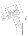
- reference numerals 1, 5 and 6 are synchrotron radiation beam, a mask and a semiconductor wafer which is to be exposed to the radiation.
- the apparatus comprises a stationary or fixed mirror 2 for expanding the synchrotron beam, an exposure chamber 3 filled with helium gas or the like, a window 4 of the exposure chamber 3 made of beryllium, a wafer stage 7, a spring 8, a wafer stage driver 9 and a frame 10
- the apparatus further comprises movable aperture blades 11 and 12, supporting members 13 and 14 for the movable aperture blades and drivers 15 and 16 for the movable aperture blades.
- the movable aperture blades 11 and 12, the supporting members 13 and 14 and the drivers 15 and 16 constitute an exposure control means.
- Designated by a reference 17 is an ultra-high vacuum chamber which is isolated from the exposure chamber 3, containing helium gas,by the window 4.
- light (radiation) 1 travels through the ultra-high vacuum chamber 17 and is expanded by the mirror 2, and is passed through the window 4.
- the exposure control means controlled by a shutter controller 20 limits the light 1, and the limited light is projected onto the semiconductor wafer 6 through the mask 5, by which the pattern of the mask is transferred onto the semiconductor wafer 6.
- Japanese Laid-Open Patent Applications Nos. 141135/1986 and 59828/1986 disclose that the synchrotron radiation is passed through a monocrystal or a diffraction grating so as to expand the divergence angle measured in the vertical plane.
- the beam provided thereby, as it is, involves non-uniformity and variation in the spectral distribution in the vertical direction, so that it is still not possible to project the mask pattern onto the wafer with uniform exposure amount.
- Japanese Laid-Open Patent Application No. 104438/1981 discloses that a shutter is driven with control to quake uniform the exposure amount over each shot area on the basis of exposure beam profiles predicted beforehand.
- the area in which the intensity of the exposure radiation is uniform is relatively wide, and therefore, a measurement at the marginal area of the mask is not much different from the intensity in the exposure area, but in the SOR exposure, the region in which the intensity of the SOR is uniform is narrow, so that the X-ray intensity is different at the marginal measuring position than at the exposure area.
- a retractable X-ray detector is advanced into the exposure area when the exposure operation is not carried out, and it detects the X-ray intensity, whereas during the exposure, the detector is retracted so as not to block the X-rays.
- X-ray intensity varies with time as in SOR, it is possible that the X-ray intensity is different at the time of the exposure to that at the time of measurement with the result of an additional error.
- the present invention is intended to provide an X-ray exposure apparatus which can determine X-ray intensity with high accuracy when SOR is used.
- Exposure apparatus in accordance with this invention is defined in claim 1 appended.
- the X-ray intensity during an exposure operation for a shot can be correctly predicted both from one or more X-ray measurements after the orbit electron injection and from the attenuation curve of the orbit electron amount.
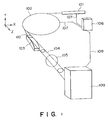
- FIG. 2 there is shown an exposure apparatus according to an embodiment of the present invention.
- reference numerals 101 and 102 designate a linear accelerator and an accumulation ring, respectively.
- the linear accelerator 101 serves to inject electrons into the ring 102.
- the linear accelerator 101 and the ring 102 are connected to a controller 106 for controlling the synchrotron system through a control line 107, so that a synchrotron radiation generating apparatus is constituted. Since the controller 106 is connected to an exposure apparatus 109 through a communication line 108, the electron injection timing by the linear accelerator 101 is transmitted to the exposure apparatus 109, so that the exposure apparatus 109 can be synchronously operated in accordance with an output of the synchrotron.
- the synchrotron radiation 110 produced from the accumulation ring 102 is expanded in the divergence angle in a Y direction (vertical direction) by an X-ray reflecting mirror 103 into an expanded radiation 104, which is introduced into the exposure apparatus through a transmitting window 105.
- the window 105 is durable against a pressure difference between the synchrotron side and the exposure apparatus side, and is made of beryllium or the like.
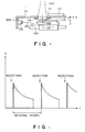
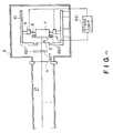
- FIG 3 is a sectional view of an inside of the exposure apparatus 109 of Figure 2, seen from the positive side of the y axis.
- the exposure apparatus 109 is provided with a casing or frame 121.
- a shutter 111 and a shutter controlling unit 112 are mounted to control the amount of synchrotron radiation 104 incident on the mask 114 and a wafer 113.
- an X-ray detector 118 for measuring the intensity of the incident X-ray is mounted, so that the X-ray intensity is detected through the mask 114 at any position in an exposure shot area by movement of the stage.
- a laser interferometer 115, its optical axis 116, a mirror 117 on the stage 119 and a guide 120 constitute a control system for positioning the stage 119 in an X-Y plane with high accuracy.
- Figure 4 is a graph showing change of the radiation intensity of the radiation produced by the synchrotron radiation generator with time.
- the intensity of the synchrotron radiation logarithmically decreases with time.
- the interval period of the electron injections is different depending on the individual synchrotron rings, but it is generally several hours.
- the hatched portion in a graph indicates the time period in which the profile (illuminance distribution) of the synchrotron radiation intensity incident on the exposure apparatus 109 is measured.
- the intensity measurement is performed when the intensity of the incident synchrotron radiation is substantially highest, by which the data has substantially the highest S/N ratio.
- the profile itself for each of the electron injection does not change.
- the measuring step is applied to the time when the material covering the window 105 is exchanged.
- the material is beryllium, it is contaminated more and more with normal exposure operation of the exposure apparatus 109 with the result of reduction of the transmissivity. Therefore, the profile is stored on the assumption that the contamination occurs uniformly over the entire area of the transmitting window 105.
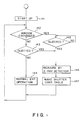
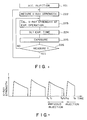
- FIG. 5 is a flow chart showing the process steps in the operation.
- the exposure apparatus 109 is started.
- the discrimination is made as to whether or not the window material 105 is exchanged. If it is exchanged, the electron injection into the ring 102 is waited for (step 145).
- the X-ray detector 118 detects the profile (step 146). The measurement is performed for each of several positions predetermined within the exposure area, while the stage 119 carrying the X-ray detector 118 is moved on the X-Y plane, more particularly, along Y axis.
- a shutter controlling table is produced (step 147).
- the discrimination is made as to whether or not the electron injection into the ring 102 is carried out or not at step 143. If it is immediately after the electron injection, the sequence goes to step 146 where the X-ray detector 118 effects measurement to determine illuminance distribution. If the electron injection is not carried out, the normal exposure operation is performed (step 144). When the profile does not much change for the respective electron injections, it is possible to advance to the normal exposure operation (step 144) similarly to the case of no electron injection, even immediately after the electron injection.
- the illuminance distribution of the synchrotron radiation adjacent the mask 114 or the wafer 113 is determined on the basis of the measurement immediately after the electron injection into the ring 102 after the exchange of the window 105 material, by which the profile data can be obtained with high S/N ratio.
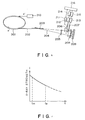
- FIG. 6 is a general arrangement of an X-ray exposure apparatus according to another embodiment of the present invention, wherein a fixed mirror is used.
- a reference numeral 201 designates an SOR ring.
- the apparatus comprises an X-ray mirror 203, an X-ray transmitting window made of beryllium (Be) or the like, a movable X-ray detector 206 and a shutter 207.
- Designated by reference numerals 208 and 209 are an X-ray mask and a wafer coated with a resist sensitive to the SOR radiation.
- the synchrotron radiation 202 is expanded by the X-ray mirror 203 into expanded radiation (X-ray) 204.
- the apparatus further comprises an electron injection 210, a signal processor 211, an X-ray detector driver 212, a shutter driver 213, an X-ray detector controller 214, a shutter controller 215 and a CPU (central processing unit) 216.
- an exposure operation using the SOR is started after low energy electrons are injected by the injector 210 into the SOR ring 201, and they are accelerated up to a predetermined energy level.
- the number of electrons injected gradually decreases due to the collision with gas molecules or the like remaining in the orbit in the SOR ring 201, with the result that the intensity of the radiation decreases. Therefore, when the number of orbit electrons or the intensity of the radiated X-rays becomes below a predetermined value, the electrons are stopped, and the exposure operation is interrupted. Thereafter, the electrons are injected again, and then the exposure operation is resumed.
- the operation of the X-ray exposure apparatus of Figure 6 will be described.
- the shutter 207 is closed (broken line in Figure 6 )
- the electrons are injected by the injector 210 into the SOR ring 201 and are accelerated at step 221.
- the CPU 216 instructs exposure intensity measurement to detect the X-ray intensity.
- the X-ray detector 206 is advanced into the exposure area by the X-ray detector driver 212 through the X-ray detector controller 214 (broken lines in Figure 6), by which the X-ray intensity is detected.
- the detected X-ray intensity is transmitted to the CPU 216 through the signal processor 211, and the X-ray detector 206 is retracted to outside the exposure area.
- the CPU 216 calculates an X-ray intensity Ie during the exposure on the basis of the X-ray intensity detected.
- the exposure time T is calculated from the set exposure amount D and the calculated level and it is set. Simultaneously, the alignment operation between the X-ray mask 208 and the wafer 209 is carried out.
- the CPU 216 instructs the shutter controller 215 to start exposure operation, in response to which the shutter driver 213 opens the shutter 207 to start the exposure. When the exposure period T elapses after the start of the exposure, the shutter 207 is closed.
- the discrimination is made as to whether or not the intensity detection is performed. If so, the sequence goes to 222, and if not, it goes to step 223.
- the X-ray intensity Ie during the exposure is determined in consideration of the attenuation of the intensity in the following manner.
- Figure 7 is a graph showing the change of the X-ray intensity I with time t.
- the abscissa and ordinate represent time t and X-ray intensity I, respectively. It is assumed that the X-ray intensity is detected at the point of time tm, and the exposure operation is started at the point of time te.
- "Accelerator Science", vol. 12, No. 2, P. 95 states that ⁇ is given by: ⁇ is 1x10 -27 x (1/p) x (1/ ⁇ T ) where p is a degree of vacuum, and ⁇ T is a crosssectional area of collision.
- the equation for correction may be different from equation (1).
- the X-ray intensity of 150 mw/cm 2 is detected at 30 sec under the conditions that the life of the electrons is 3600 sec in the SOR ring and that the target exposure illuminance is 50 mJ/cm 2
- the X-ray intensity Ie at the respective exposure times and the exposure period t is calculated as given in Table 1 below using the equation (1), where the transmissivity of the mask is assumed 50 %.
- Table 1 TIME OF EXP. X-RAY INTENSITY (mw/cm 2 ) EXP. PERIOD 60 sec 148.8 0.67 sec 120 146.3 0.68 180 143.9 0.70 600 128.0 0.78
- the X-ray intensities for the exposure operations can be determined by the equation (1) or another until the re-injection, if the X-ray intensity is detected once after the electron injection.
- the detections are performed at regular intervals, for example, immediately before the respective exposure operations, the X-ray intensity during the exposure can be determined more accurately. If the number of exposure operations is to be increased, it is possible to effect the detecting operation during the wafer exchanging operation.
- Figure 9 shows the changes in the X-ray intensity I with time t when the electron injection is carried out plural times.
- the electrons are injected at the point of time ti, and the electrons are blocked at the point of time tc by which the orbit current becomes zero.
- the X-ray intensity is measured at the times t1 and t2, and the detected intensities are I(t1) and I(t2).
- the electron life is determined if the X-ray intensity is detected twice for one electron injection.
- three or more detections are performed at regular intervals for one electron injection, and the electron life is determined as an average or using least square approximation.
- the intensity is detected at such intervals that the X-ray intensity attenuates by a predetermined degree from the past data, and then the electron life ⁇ is correctly determined with small number of detections. For example, assuming that the electron life determined on the basis of the past data is ⁇ , and the detection is performed for every 5 % attenuation, the detection timing is 0.051 ⁇ , 0.105 ⁇ , 0.16 ⁇ and 0.22 ⁇ .
- the electron life ⁇ Upon determination of the electron life ⁇ , not only the data at the immediately previous injection, but also further previous data may be used. If two or more detecting operations are already carried out for the current injection, the data are usable. In this case, different weights may be placed on the data depending on the difference in the points of detection times.
- the electron life ⁇ may be corrected using the equation (2).
- the electron life ⁇ e (Pm ⁇ m)/Pe where Pm and ⁇ m are a degree of vacuum and the electron life during the detection, and Pe is the degree of vacuum during the exposure.
- the X-ray intensity during the exposure period te can be determined on the basis of the equation (1).
- the X-ray intensity during the exposure operation is predicted from the X-ray intensity detected after the orbit electrons are injected and the attenuation curve of the X-ray intensity. Therefore, when the X-ray intensity during the exposure cannot always be measured, and when the X-ray detector is advanced into the exposure area during the non-exposure-operation to detect the X-ray intensity, the X-ray intensities during the exposure operation can still be determined with high accuracy.
- the difference between the detected intensity and the intensity during the exposure operation can be reduced when the attenuation of the radiation is large, or when the time interval between the X-ray intensity detection and the exposure operation is long.
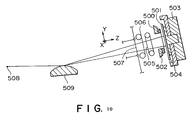
- Figure 10 shows an exposure apparatus to which a further embodiment of the present invention is applicable, wherein reference numerals 501 and 502 designate a wafer and a mask, respectively, wherein the mask is disposed parallel to the wafer 501 with a gap of approximately 40 ⁇ m in a z direction.
- the apparatus comprises a mask stage 500 for supporting the mask 502, a wafer moving space 503 for supporting and moving the wafer 501.
- the exposure apparatus is a so-called stepper exposure apparatus wherein the exposure areas sequentially stepped to expose all of the exposure areas of the wafer are exposed.
- the apparatus further comprises a sensor 504 mounted on the wafer moving stage 503 to detect the intensity of the illuminating radiation incident on the wafer 501 at a given point in the exposure area.
- a movable aperture stop 505 has an opening to constitute an exposure shutter together with an auxiliary shutter 506.
- Designated by a reference 507 is a thin film of beryllium.
- the space between the thin film 507 and the mask 502 contains pressure-reduced helium, and the space between the mask 502 and the radiation source is a ultra-high vacuum space.
- a radiation emitting point of the SOR ring which is an X-ray source is designated by a reference 508.
- the intensity of the synchrotron radiation is uniform in a direction parallel to a plane including the orbit of the electron beam, but the intensity is not uniform in the vertical direction, and is symmetrical.
- a convex cylindrical mirror 509 functions to expand the synchrotron radiation in the direction in which the radiation has the intensity distribution (y axis direction), so that the radiation can illuminate the exposure area required at the position of the mask 502 and the wafer 501 in the exposure apparatus.
- the illuminance intensity is a one-dimensional distribution having one peak in the exposure area.
- Figure 11 shows an example of calculated illuminance distribution weighed in consideration of the dependency, on the wavelength of the sensitivity of the resist applied on the wafer 501.
- Figure 12 schematically shows the appearance of the exposure shutter 505 and a driving profile.
- a belt 521 is stretched between the drums 528 and 529 and is made of stainless steel, for example, and the thickness is sufficient to block the X-rays.
- the aperture 524 is defined by a leading edge 526 and the trailing edge 527.
- the time period between the passage of the leading edge 526 at the view angle (exposure start) and the passage of the trailing edge 527 at the view angle (exposure end) is the time period of exposure.
- another opening is formed so as not to block the exposure through the aperture 524 in the view angle.
- the drive profile of the shutter 505 in the graph of Figure 12
- the area between Y1 - YN corresponds to the view angle to be exposed.
- an area of a small region ⁇ Y defined by the leading edge 526 and the trailing edge 527 is an amount of exposure at a point in the view angle.
- the amount of exposure at each of such point can be controlled one-dimensionally by moving the movable aperture 524 in a driving profile.
- the driving profile is so selected that the illuminance distribution of Figure 11 is uniformized.
- the intensity attenuation of the radiation provided by the synchrotron radiation source is logarithmic from the time of electron injection from linear accelerator, as shown in Figure 15. Therefore, it is preferable that the driving profile of the exposure shutter is changed for each of the exposure operations on the basis of the intensity detection from the radiation source, so that the desired amount of exposure can be provided for each of the shot areas.
- the intensity of the synchrotron radiation is detected by a detector 504 ( Figure 10) in this embodiment.
- the driving profile is expanded or contracted in the direction of the time axis, thus providing the desired exposure amount.
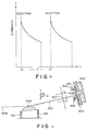
- Figures 13 and 14 show an example.
- Figure 14 shows an expanded driving profile provided by expanding the Figure 12 driving profile only in the direction of the time axis (abscissa). This is applicable when the intensity of the synchrotron radiation by the radiation source is low.
- Figure 14 shows the opposite case.
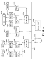
- FIG 16 shows a system structure for accomplishing the above function.
- the system comprises driving motors 541 and 542 for driving the auxiliary shutter 506 and the main shutter 505 of Figure 10
- the motors 541 and 542 are pulse motors or DC motors driven by motor drivers 543 and 544, respectively.
- Pulse generators 547 and 548 supply pulses to the motor driver 543 and 544, and in response to each of the pulses, the motor 541 or 542 is rotated by a predetermined angle accurately.
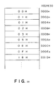
- the pulse generator 547 and 548 are provided with RAM which stores a table shown in Figure 20, for example. The contents of the table correspond to the pulse intervals produced from the pulse generators 547 and 548.
- a subordinate CPU (central processing unit) 550 controls the main shutter 505 and the auxiliary shutter 506 and controls the pulse generators 547 and 548 through a local bus line 556.
- a signal from the sensor 504 for the illuminance detection mounted on the stage 507 shown in Figure 11 is converted into a digital signal by a detector signal processing unit 550.
- the stage 503 is driven by a driving motor which is driven by a motor driver 545, and the positioning of the stage 503 is effected by a motor driver 546.
- a stage actuator controlling unit 551 controls the position of the stage 503.
- Designated by reference numerals 552 and 553 are a laser interferometer and a control unit for distance measurement, respectively. Those elements are effective to correctly measure the position of the wafer 501 carried on the wafer stage 503.
- the stage controlling unit 551 and the controlling unit 553 for the distance measuring system are controlled by the subordinate CPU 554.
- a detector signal processing unit 550 and the subordinate CPU 554 for the stage side are connected, and therefore, the illuminance of the exposure radiation can be effected at any point in the exposure area synchronously, and the detection can be stored in the memory 558 for the respective points in the exposure area by the instructions by the main controller 559.
- a shutter driving table ( Figure 20) for providing the desired exposure distribution from the contents stored in the memory 558, and the table data are supplied to the RAM of the pulse generators 547 and 548, and they drive the associated motors.
- the illuminance is detected by the sensor 504, and if the radiation intensity of the illumination source attenuates as compared with the previous shot, for example, the driving table of Figure 20 is corrected by mathematically by the main controller 559.
- the driving profile 29 is modified by changing the pulse intervals of the pulse generators 547 and 548 so as to provide the desired proper exposure amount distribution.
- the driving table first produced is stored as a source table together with the data of the illuminance of the exposure radiation when the data are obtained.
- Figure 16 shows another structure of the exposure apparatus to which an embodiment of the present invention is applicable. Since this embodiment is similar to Figure 10 embodiment, the same reference numerals as in Figure 10 are assigned to the elements having the corresponding functions, and the description thereof are omitted for simplicity.
- exposure apparatus uses a movable aperture 505 to limit the exposure amount, but in the apparatus of this embodiment, the mirror 509 is swung to control the exposure amount.
- the mirror 509 expands the SOR in the direction of the Y axis to illuminate a part of the mask 502 and a part of the wafer 501.
- the mirror 509 is swung by an actuator mechanism 531.
- the actuator mechanism 531 swings the mirror 509 in the direction y and in the direction Wx (x axis rotational direction).
- the reflected radiation is deflected in y direction, and therefore, the entire area of the mask 502 is illuminated by the exposure radiation.
- the spectral distribution and the intensity of the deflected radiation are different depending on the angle of incidence of the synchrotron radiation from the radiation source, and therefore, the exposure amount distribution is not uniform if the scanning is at constant speed in the Y direction.
- a mirror swinging profile as shown in Figure 16 is produced, and in accordance with this profile, the mirror 509 is swung to avoid the non-uniformity of the exposure.
- the radiation source intensity changes similarly to the case of Figure 10 the profile is expanded or contracted in the direction of the time axis as shown in Figure 18 so as to provide a desired exposure amount.
- an increase of the intensity of the radiation by the radiation source is compensated by contraction of the time axis of the profile, thus providing a desired amount of exposure.
- Figure 16 The system arrangement of Figure 16 embodiment is similar to Figure 10 embodiment. However, in Figure 19, the mechanical structures of the actuators 541 and 542 and the motor drivers 543 and 544 are modified to swing the mirror 509 in Figure 16. According to this embodiment, the necessity for producing the driving profile for driving the exposure amount controlling device of the exposure apparatus for each of the exposure shots is avoided, and simply by expanding and contracting the time axis of the profile once produced, the proper exposure distribution can be provided at all times quickly in response to the intensity change of the radiation by the radiation source. Therefore, the calculation process for repeatedly producing the profile has been greatly simplified.
- Figure 21 shows a further embodiment.
- the same reference numerals as in Figure 1 are assigned to the elements having the corresponding functions, and the detailed description of those elements are omitted for simplicity.
- the detector 622 detects the beam intensity of the synchrotron radiation for a necessary period of time, and the shutter controller determines a time constant ⁇ (generally called as "electron life") of the attenuation using least square approximation.
- the time constant ⁇ of the attenuation may be the one determined beforehand. If the attenuation characteristics are determined in this manner, the beam intensity of the synchrotron radiation can be calculated at any point of time.
- the calculation is performed by the shutter controller 20. As shown in Figure 39 the aperture limiting or defining member 11 of the movable aperture stop 1 driven by the driver 15 for 121 sec from the time T1 to the time T2 at a speed of (Y2-Y1)/121 in the direction +Y, and thereafter, it is stopped.
- (1) shows a relationship between a position of an edge surface 18 ( Figure 3) of the opening limiting member 11 of the movable aperture and the time.
- the opening limiting member 12 of the movable aperture stop is moved from the time T2 in the direction +Y by the driver 16.
- the shutter controller calculates the driving speed of the edge surface 19 to provide uniform amount of exposure within the angle of view 21 by the following equation:
- Y is a position of the edge surface 19 ( Figure 3) of the opening limiting member 12 of the movable aperture stop at the time t.
- the speed v at which the limiting member 11 of the movable aperture stop moves in the direction +Y is: (Y2-Y1)/(T2-T1)
- the limiting member 12 of the movable aperture stop is moved from the time T2 at the following speed: v ⁇ e -t/ ⁇ /(e -t/ ⁇ + 1 - e -T2/ ⁇ ) where ⁇ is a timing constant of the beam attenuation.
- the exposure amount within the view angle 21 is substantially uniformly 120 mJ/cm 2 , so that the mask pattern can be transferred onto the wafer with high resolution.
- FIG 23 shows a further embodiment.
- a mirror 602 is disposed in the ultra-high vacuum ambience 17.
- the mirror 602 is supported by a supporting rod 623 for rotation about an axis 624.
- a driving rod 625 is connected to the mirror 602.
- the driving rod 625 is driven by a driver 626.
- the driver 626 is controlled by a mirror controller 620 which drives the driving rod 625 to swing the mirror 602 to scanningly illuminate the mask 5 and the wafer 6 with the SOR radiation reflected by the mirror 602.
- the X-ray detector 622 mounted on the wafer stage 7 the change of the beam intensity of the synchrotron radiation is detected while the wafer stage 7 is being moved before the exposure operation.
- Figure 24 is an enlarged view of the shutter 627. The beam is indicated by hatched portion.
- the synchrotron radiation has a Gaussian distribution in the direction perpendicular to the beam, that is, in the plane z-y.
- the amount of exposure within the view angle 21 is substantially uniformly 100 mJ/cm 2 .
- Figure 25 shows a further embodiment.
- the rotational speed of the mirror 602 is changed to compensate the attenuation, with time, of the beam intensity of the synchrotron radiation.
- the shutter 627 is fixed during the exposure operation, whereas the moving speed of the stage 7 is changed during the exposure for one view angle to compensate the beam intensity attenuation to provide a constant amount of exposure.
- the driving speed of the stage 7 is determined so that the relative positional relation between the beam and the view angle 21 is the same as that in Figure 23 embodiment.
- the amount of exposure in the view angle 21 is substantially uniformly 100 mJ/cm 2 .
- the cumulative amount of exposure in the view angle is substantially free from variation due to the attenuation, with time, of the beam intensity, so that the resolution of the exposure apparatus can be improved.
Landscapes
- Physics & Mathematics (AREA)
- General Physics & Mathematics (AREA)
- Exposure Of Semiconductors, Excluding Electron Or Ion Beam Exposure (AREA)
- Exposure And Positioning Against Photoresist Photosensitive Materials (AREA)
Claims (7)
- Belichtungseinrichtung zum Belichten eines Substrats (113, 114; 208, 209; 501, 502; 5, 6) mit einer Synchrotron-Strahlung, die von einer Synchrotron-Strahlungsquelle (102; 201; 508) erzeugt wird, mit:einer Erfassungseinrichtung (118; 206; 604; 662), die zum Erfassen der Intensität der Synchrotron-Strahlung zu einem Zeitpunkt, der einer Elektroneninjektion in einen Ring der Synchrotron-Strahlungsquelle (102; 201; 508) unmittelbar folgt, wirksam ist;einer Belichtungssteuereinrichtung (111, 112; 207; 505, 506; 11, 12, 16; 602), die in einem Strahlungspfad zwischen der Synchrotron-Strahlungsquelle und dem Substrat (113, 114; 208, 209; 501, 502; 5, 6) anzuordnen ist, wobei die Belichtungssteuereinrichtung ein bewegliches Element (111; 207; 505, 506; 11, 12; 602; 707) zum ausgewählten Begrenzen der Synchrotron-Strahlung auf dem Substrat enthält;einer Bestimmungseinrichtung (106; 216; 559; 20) zum Bestimmen eines Treibprofils zum Treiben des beweglichen Elements, um bei jedem Belichtungsvorgang trotz Dämpfung der Intensität der Synchrotron-Strahlung mit der Zeit eine konstante Belichtungsmenge für das Substrat zur Verfügung zu stellen, wobei die Bestimmungseinrichtung (106; 216; 559; 20) eingerichtet ist, um das Treibprofil aus der Intensität, die durch die Erfassungseinrichtung zum Zeitpunkt unmittelbar folgend einer Elektroneninjektion in den Ring erfaßt wird, zu bestimmen, indem eine Intensitätsdämpfung der Synchrotron-Strahlung (104; 204; 532) auf der Grundlage einer Dämpfungskurveninformation für in den Ring injizierte Elektronen berechnet wird; undeiner Treibeinrichtung (213, 215; 543, 544, 555; 620) zum Treiben des beweglichen Elements (111; 207; 505, 506; 11, 12; 602) der Belichtungssteuereinrichtung (111, 112; 207; 505, 506; 11, 12, 16; 602) in Übereinstimmung mit dem durch die Bestimmungseinrichtung (106; 216; 559; 20) bestimmten Treibprofil.
- Einrichtung nach Anspruch 1,
dadurch gekennzeichnet, daß
das bewegliche Element einen beweglichen Verschluß (111, 207, 505, 506; 11, 12) umfaßt. - Einrichtung nach Anspruch 1,
dadurch gekennzeichnet, daß
das bewegliche Element (111; 207; 505, 506; 11, 12; 602) einen beweglichen Spiegel (602) umfaßt. - Einrichtung nach Anspruch 1,
dadurch gekennzeichnet, daß
die Erfassungseinrichtung (118; 206; 604; 662) einen Röntgenstrahl-Detektor umfaßt. - Einrichtung nach Anspruch 4,
dadurch gekennzeichnet, daß
der Röntgenstrahl-Detektor in und zwischen einem Belichtungsbereich beweglich ist. - Verfahren zum Verwenden der Belichtungseinrichtung nach einem der Ansprüche 1 bis 5 mit einer Synchrotron-Strahlungsquelle (102; 201; 508), wobei
die Belichtungssteuereinrichtung (111; 112; 207; 505; 506; 11, 12, 16; 602) in einem Strahlungspfad zwischen der Synchrotron-Strahlungsquelle (102; 201; 508) und einem zu belichtenden Substrat (113, 114; 208, 209; 501, 502; 5, 6) angeordnet ist; und eine Belichtung des Substrats unter Verwendung der Belichtungssteuereinrichtung (111, 112; 207; 505, 806; 11, 12, 16; 602) gesteuert wird, um eine Synchrotron-Strahlung auf dem Substrat ausgewählt zu begrenzen. - Verfahren zum Erzeugen einer Halbleiterschaltungseinrichtung, bei der ein Halbleiterwafer (6) mit einer Synchrotron-Strahlung, die über eine Maske (5) darauf projiziert wird, belichtet wird, indem eine Belichtungseinrichtung nach einem der Ansprüche 1 bis 5 in Übereinstimmung mit dem Verfahren aus Anspruch 6 verwendet wird.
Priority Applications (1)
| Application Number | Priority Date | Filing Date | Title |
|---|---|---|---|
| EP95202632A EP0694817B1 (de) | 1988-09-02 | 1989-08-31 | Belichtungsapparat |
Applications Claiming Priority (14)
| Application Number | Priority Date | Filing Date | Title |
|---|---|---|---|
| JP63218522A JP2700392B2 (ja) | 1988-09-02 | 1988-09-02 | 露光装置 |
| JP218522/88 | 1988-09-02 | ||
| JP63222253A JPH0271508A (ja) | 1988-09-07 | 1988-09-07 | 露光装置 |
| JP222251/88 | 1988-09-07 | ||
| JP222253/88 | 1988-09-07 | ||
| JP63222251A JP2750582B2 (ja) | 1988-09-07 | 1988-09-07 | X線露光方法 |
| JP63223483A JP2640247B2 (ja) | 1988-09-08 | 1988-09-08 | 露光装置 |
| JP223483/88 | 1988-09-08 | ||
| JP227389/88 | 1988-09-13 | ||
| JP63227388A JP2741039B2 (ja) | 1988-09-13 | 1988-09-13 | 露光装置 |
| JP63227389A JPH0276215A (ja) | 1988-09-13 | 1988-09-13 | 露光装置 |
| JP227388/88 | 1988-09-13 | ||
| JP133795/89 | 1989-05-26 | ||
| JP1133795A JP2877352B2 (ja) | 1989-05-26 | 1989-05-26 | X線露光装置 |
Related Child Applications (2)
| Application Number | Title | Priority Date | Filing Date |
|---|---|---|---|
| EP95202632.6 Division-Into | 1989-08-31 | ||
| EP95202632A Division EP0694817B1 (de) | 1988-09-02 | 1989-08-31 | Belichtungsapparat |
Publications (3)
| Publication Number | Publication Date |
|---|---|
| EP0357425A2 EP0357425A2 (de) | 1990-03-07 |
| EP0357425A3 EP0357425A3 (de) | 1991-09-18 |
| EP0357425B1 true EP0357425B1 (de) | 1996-11-06 |
Family
ID=27566014
Family Applications (2)
| Application Number | Title | Priority Date | Filing Date |
|---|---|---|---|
| EP89308823A Expired - Lifetime EP0357425B1 (de) | 1988-09-02 | 1989-08-31 | Belichtungseinrichtung |
| EP95202632A Expired - Lifetime EP0694817B1 (de) | 1988-09-02 | 1989-08-31 | Belichtungsapparat |
Family Applications After (1)
| Application Number | Title | Priority Date | Filing Date |
|---|---|---|---|
| EP95202632A Expired - Lifetime EP0694817B1 (de) | 1988-09-02 | 1989-08-31 | Belichtungsapparat |
Country Status (3)
| Country | Link |
|---|---|
| US (1) | US5157700A (de) |
| EP (2) | EP0357425B1 (de) |
| DE (2) | DE68929187T2 (de) |
Families Citing this family (34)
| Publication number | Priority date | Publication date | Assignee | Title |
|---|---|---|---|---|
| US5365561A (en) * | 1988-03-25 | 1994-11-15 | Canon Kabushiki Kaisha | Exposure control in an X-ray exposure apparatus |
| EP0359370B1 (de) * | 1988-09-14 | 1996-01-03 | Canon Kabushiki Kaisha | Belichtungssteuerung in einem Röntgenbelichtungsapparat |
| JP2770960B2 (ja) * | 1988-10-06 | 1998-07-02 | キヤノン株式会社 | Sor−x線露光装置 |
| EP0425739B1 (de) * | 1989-10-30 | 1995-02-22 | Canon Kabushiki Kaisha | Ausrichtevorrichtung und eine damit versehene Synchrotron-Röntgenbelichtungsvorrichtung |
| DE69126719T2 (de) * | 1990-03-09 | 1997-11-06 | Canon K.K., Tokio/Tokyo | Belichtungsvorrichtung |
| JP3025545B2 (ja) * | 1991-03-18 | 2000-03-27 | キヤノン株式会社 | X線リソグラフィ用マスクおよびx線リソグラフィ露光装置 |
| EP0588579B1 (de) * | 1992-09-14 | 1998-12-02 | Canon Kabushiki Kaisha | Synchrotron-Röntgenbelichtungsverfahren |
| JP3049680B2 (ja) * | 1993-06-14 | 2000-06-05 | キヤノン株式会社 | ビーム位置検出装置及びこれを用いたシステム |
| JP3291408B2 (ja) * | 1994-04-04 | 2002-06-10 | キヤノン株式会社 | 露光装置および集積回路の製造方法 |
| US5835560A (en) * | 1994-05-24 | 1998-11-10 | Canon Kabushiki Kaisha | Exposure apparatus |
| JPH07321024A (ja) * | 1994-05-25 | 1995-12-08 | Canon Inc | 位置決め方法およびその装置ならびにこれらを用いた露光装置 |
| JP3391940B2 (ja) * | 1995-06-26 | 2003-03-31 | キヤノン株式会社 | 照明装置及び露光装置 |
| JP3666951B2 (ja) | 1995-10-06 | 2005-06-29 | キヤノン株式会社 | マーク検出方法、これを用いた位置合わせ方法、露光方法及び装置、ならびにデバイス生産方法 |
| US5920398A (en) * | 1996-03-01 | 1999-07-06 | Canon Kabushiki Kaisha | Surface position detecting method and scanning exposure method using the same |
| JP3862347B2 (ja) * | 1996-04-11 | 2006-12-27 | キヤノン株式会社 | X線縮小露光装置およびこれを利用したデバイス製造方法 |
| JP3284045B2 (ja) * | 1996-04-30 | 2002-05-20 | キヤノン株式会社 | X線光学装置およびデバイス製造方法 |
| US6559465B1 (en) | 1996-08-02 | 2003-05-06 | Canon Kabushiki Kaisha | Surface position detecting method having a detection timing determination |
| JP3337921B2 (ja) | 1996-08-23 | 2002-10-28 | キヤノン株式会社 | 投影露光装置および位置合せ方法 |
| KR0174997B1 (ko) * | 1996-12-20 | 1999-03-20 | 김광호 | 노광설비의 이중노광 방지장치 |
| JP3689516B2 (ja) * | 1997-01-29 | 2005-08-31 | キヤノン株式会社 | 電子ビーム露光装置 |
| JP2000294523A (ja) * | 1999-04-01 | 2000-10-20 | Sony Corp | 半導体製造装置および半導体装置の製造方法 |
| US6484088B1 (en) * | 1999-05-04 | 2002-11-19 | Ssi Technologies, Inc. | Fuel optimization system with improved fuel level sensor |
| US6573732B1 (en) * | 1999-05-04 | 2003-06-03 | Ssi Technologies, Inc. | Dynamic range sensor and method of detecting near field echo signals |
| US6295332B1 (en) * | 1999-06-12 | 2001-09-25 | Robert Allen Selzer | Method of improving x-ray lithography in the sub 100nm range to create high quality semiconductor devices |
| JP2000357644A (ja) | 1999-06-14 | 2000-12-26 | Canon Inc | 露光方法及び露光装置 |
| JP2000357643A (ja) | 1999-06-14 | 2000-12-26 | Canon Inc | 露光方法及びそれを用いた露光装置 |
| US6954255B2 (en) * | 2001-06-15 | 2005-10-11 | Canon Kabushiki Kaisha | Exposure apparatus |
| US6934003B2 (en) * | 2002-01-07 | 2005-08-23 | Canon Kabushiki Kaisha | Exposure apparatus and device manufacturing method |
| JP2003297891A (ja) * | 2002-01-31 | 2003-10-17 | Rigaku Industrial Co | 半導体用蛍光x線分析装置 |
| US20070147579A1 (en) * | 2005-12-23 | 2007-06-28 | De Man Bruno K B | Method and system for radiographic imaging with organ-based radiation profile prescription |
| JP4789260B2 (ja) * | 2006-08-23 | 2011-10-12 | エスアイアイ・ナノテクノロジー株式会社 | 荷電粒子ビーム装置及びアパーチャの軸調整方法 |
| EP2461347A1 (de) | 2010-12-06 | 2012-06-06 | Fei Company | Detektorsystem für Transmissionselektronenmikroskop |
| DE102016220096B3 (de) * | 2016-10-14 | 2018-02-08 | Siemens Healthcare Gmbh | Verfahren zur Generierung von Röntgenbilddaten |
| US20180333657A1 (en) * | 2017-05-17 | 2018-11-22 | Sable Sand Solutions Inc. | Detection of contents of a sand separator using radiation |
Family Cites Families (17)
| Publication number | Priority date | Publication date | Assignee | Title |
|---|---|---|---|---|
| DE2722958A1 (de) * | 1977-05-20 | 1978-11-23 | Siemens Ag | Verfahren zur justierung einer halbleiterscheibe relativ zu einer bestrahlungsmaske bei der roentgenstrahl-fotolithografie |
| JPS5645026A (en) | 1979-09-20 | 1981-04-24 | Matsushita Electric Ind Co Ltd | Forming method for resin film on semiconductor substrate |
| JPS6037616B2 (ja) | 1980-01-24 | 1985-08-27 | 理学電機株式会社 | X線リゾグラフイ装置 |
| JPS57101839A (en) | 1980-12-18 | 1982-06-24 | Nippon Kogaku Kk <Nikon> | Exposure device for wafer or photomask |
| JPS57117238A (en) * | 1981-01-14 | 1982-07-21 | Nippon Kogaku Kk <Nikon> | Exposing and baking device for manufacturing integrated circuit with illuminometer |
| EP0083394B1 (de) * | 1981-12-31 | 1986-04-09 | International Business Machines Corporation | Verfahren und Vorrichtung für die gleichmässige Beleuchtung einer Fläche |
| JPS5952246A (ja) * | 1982-09-20 | 1984-03-26 | Nippon Kogaku Kk <Nikon> | 露光制御装置 |
| JPS59198726A (ja) | 1983-04-26 | 1984-11-10 | Fujitsu Ltd | Mic装置の製造方法 |
| JPS6084814A (ja) | 1983-06-22 | 1985-05-14 | Agency Of Ind Science & Technol | X線投射装置 |
| JPS60198726A (ja) | 1984-03-23 | 1985-10-08 | Hitachi Ltd | X線露光装置の露光量調整方法と装置 |
| JPS6159828A (ja) | 1984-08-31 | 1986-03-27 | Nippon Telegr & Teleph Corp <Ntt> | X線リソグラフイ装置 |
| JPS61113065A (ja) | 1984-11-07 | 1986-05-30 | Hitachi Ltd | 露光装置 |
| JPS61141135A (ja) | 1984-12-14 | 1986-06-28 | Hitachi Ltd | X線リソグラフイ装置 |
| JPS61276223A (ja) | 1985-05-30 | 1986-12-06 | Fujitsu Ltd | X線露光方法 |
| JPS6414918A (en) * | 1987-07-08 | 1989-01-19 | Nikon Corp | Stepper |
| AT393334B (de) * | 1988-01-22 | 1991-09-25 | Ims Ionen Mikrofab Syst | Anordnung zur stabilisierung einer bestrahlten maske |
| US4804978A (en) * | 1988-02-19 | 1989-02-14 | The Perkin-Elmer Corporation | Exposure control system for full field photolithography using pulsed sources |
-
1989
- 1989-08-31 EP EP89308823A patent/EP0357425B1/de not_active Expired - Lifetime
- 1989-08-31 EP EP95202632A patent/EP0694817B1/de not_active Expired - Lifetime
- 1989-08-31 US US07/401,615 patent/US5157700A/en not_active Expired - Fee Related
- 1989-08-31 DE DE68929187T patent/DE68929187T2/de not_active Expired - Fee Related
- 1989-08-31 DE DE68927430T patent/DE68927430T2/de not_active Expired - Fee Related
Also Published As
| Publication number | Publication date |
|---|---|
| DE68927430D1 (de) | 1996-12-12 |
| EP0694817A2 (de) | 1996-01-31 |
| EP0357425A3 (de) | 1991-09-18 |
| EP0694817B1 (de) | 2000-03-22 |
| EP0694817A3 (de) | 1996-04-10 |
| DE68929187D1 (de) | 2000-04-27 |
| DE68927430T2 (de) | 1997-03-13 |
| DE68929187T2 (de) | 2000-09-28 |
| EP0357425A2 (de) | 1990-03-07 |
| US5157700A (en) | 1992-10-20 |
Similar Documents
| Publication | Publication Date | Title |
|---|---|---|
| US5157700A (en) | Exposure apparatus for controlling intensity of exposure radiation | |
| KR101446820B1 (ko) | 마이크로리소그래피 투영 노광 장치의 조명 시스템 내의 다수의 미러 어레이들을 감시하는 방법 및 장치 | |
| JP4202181B2 (ja) | リソグラフィ装置、デバイス製造方法、性能測定方法、較正方法、およびコンピュータ・プログラム | |
| US6721039B2 (en) | Exposure method, exposure apparatus and device producing method | |
| US4920505A (en) | Projection exposure apparatus | |
| US5663784A (en) | Slit-scanning type light exposure apparatus | |
| US6268906B1 (en) | Exposure apparatus and exposure method | |
| WO1998059364A1 (en) | Projection aligner, method of manufacturing the aligner, method of exposure using the aligner, and method of manufacturing circuit devices by using the aligner | |
| US6645701B1 (en) | Exposure method and exposure apparatus | |
| JP2001144004A (ja) | 露光方法、露光装置、及びデバイス製造方法 | |
| US5131022A (en) | Exposure method and apparatus | |
| US5898480A (en) | Exposure method | |
| JPH11507146A (ja) | リソグラフィ走査露光投影装置 | |
| KR19980071344A (ko) | 노광량 제어 방법, 노광 방법 및 노광 장치와 그 제조방법 | |
| KR100588127B1 (ko) | 리소그래피장치, 디바이스제조방법 및 그것에 의하여제조된 디바이스 | |
| US6731377B2 (en) | Laser output control method, laser apparatus and exposure apparatus | |
| JP2741039B2 (ja) | 露光装置 | |
| JPH04342112A (ja) | X線リソグラフィ装置 | |
| JP2700392B2 (ja) | 露光装置 | |
| JPH09180993A (ja) | 露光装置及びデバイス製造方法 | |
| WO2025011840A1 (en) | Metrology apparatus | |
| JP2692896B2 (ja) | X線露光装置 | |
| JP2750582B2 (ja) | X線露光方法 | |
| JPH0697050A (ja) | X線露光方法 | |
| JPH0793252B2 (ja) | 露光装置 |
Legal Events
| Date | Code | Title | Description |
|---|---|---|---|
| PUAI | Public reference made under article 153(3) epc to a published international application that has entered the european phase |
Free format text: ORIGINAL CODE: 0009012 |
|
| AK | Designated contracting states |
Kind code of ref document: A2 Designated state(s): DE FR GB NL |
|
| 17P | Request for examination filed |
Effective date: 19901231 |
|
| PUAL | Search report despatched |
Free format text: ORIGINAL CODE: 0009013 |
|
| AK | Designated contracting states |
Kind code of ref document: A3 Designated state(s): DE FR GB NL |
|
| 17Q | First examination report despatched |
Effective date: 19931220 |
|
| GRAH | Despatch of communication of intention to grant a patent |
Free format text: ORIGINAL CODE: EPIDOS IGRA |
|
| GRAH | Despatch of communication of intention to grant a patent |
Free format text: ORIGINAL CODE: EPIDOS IGRA |
|
| GRAA | (expected) grant |
Free format text: ORIGINAL CODE: 0009210 |
|
| AK | Designated contracting states |
Kind code of ref document: B1 Designated state(s): DE FR GB NL |
|
| DX | Miscellaneous (deleted) | ||
| REF | Corresponds to: |
Ref document number: 68927430 Country of ref document: DE Date of ref document: 19961212 |
|
| ET | Fr: translation filed | ||
| RIN2 | Information on inventor provided after grant (corrected) |
Free format text: KUROSAWA, HIROSHI * AMEMIYA, MITSUAKI * TERASHIMA, SHIGERU * UDA, KOJI * SHIMODA, ISAMU * UZAWA, SHUNICHI * OZAWA, KUNITAKA * MORI, MAKIKO * EBINUMA, RYUICHI * HARA, SHINICHI * MIZUSAWA, NOBUTOSHI * KAWAKAMI, EIGO |
|
| PLBE | No opposition filed within time limit |
Free format text: ORIGINAL CODE: 0009261 |
|
| STAA | Information on the status of an ep patent application or granted ep patent |
Free format text: STATUS: NO OPPOSITION FILED WITHIN TIME LIMIT |
|
| 26N | No opposition filed | ||
| REG | Reference to a national code |
Ref country code: GB Ref legal event code: IF02 |
|
| PGFP | Annual fee paid to national office [announced via postgrant information from national office to epo] |
Ref country code: GB Payment date: 20030818 Year of fee payment: 15 |
|
| PGFP | Annual fee paid to national office [announced via postgrant information from national office to epo] |
Ref country code: FR Payment date: 20030828 Year of fee payment: 15 Ref country code: DE Payment date: 20030828 Year of fee payment: 15 |
|
| PGFP | Annual fee paid to national office [announced via postgrant information from national office to epo] |
Ref country code: NL Payment date: 20030831 Year of fee payment: 15 |
|
| PG25 | Lapsed in a contracting state [announced via postgrant information from national office to epo] |
Ref country code: GB Free format text: LAPSE BECAUSE OF NON-PAYMENT OF DUE FEES Effective date: 20040831 |
|
| PG25 | Lapsed in a contracting state [announced via postgrant information from national office to epo] |
Ref country code: NL Free format text: LAPSE BECAUSE OF NON-PAYMENT OF DUE FEES Effective date: 20050301 Ref country code: DE Free format text: LAPSE BECAUSE OF NON-PAYMENT OF DUE FEES Effective date: 20050301 |
|
| GBPC | Gb: european patent ceased through non-payment of renewal fee |
Effective date: 20040831 |
|
| PG25 | Lapsed in a contracting state [announced via postgrant information from national office to epo] |
Ref country code: FR Free format text: LAPSE BECAUSE OF NON-PAYMENT OF DUE FEES Effective date: 20050429 |
|
| NLV4 | Nl: lapsed or anulled due to non-payment of the annual fee |
Effective date: 20050301 |
|
| REG | Reference to a national code |
Ref country code: FR Ref legal event code: ST |