EP0360487A2 - Verfahren und Vorrichtung zur Bestimmung von in einer Flüssigkeitsprobe enthaltenen Teilchen - Google Patents
Verfahren und Vorrichtung zur Bestimmung von in einer Flüssigkeitsprobe enthaltenen Teilchen Download PDFInfo
- Publication number
- EP0360487A2 EP0360487A2 EP89309279A EP89309279A EP0360487A2 EP 0360487 A2 EP0360487 A2 EP 0360487A2 EP 89309279 A EP89309279 A EP 89309279A EP 89309279 A EP89309279 A EP 89309279A EP 0360487 A2 EP0360487 A2 EP 0360487A2
- Authority
- EP
- European Patent Office
- Prior art keywords
- liquid
- sample
- passage
- input location
- flow
- Prior art date
- Legal status (The legal status is an assumption and is not a legal conclusion. Google has not performed a legal analysis and makes no representation as to the accuracy of the status listed.)
- Granted
Links
Images






Classifications
-
- G—PHYSICS
- G01—MEASURING; TESTING
- G01N—INVESTIGATING OR ANALYSING MATERIALS BY DETERMINING THEIR CHEMICAL OR PHYSICAL PROPERTIES
- G01N35/00—Automatic analysis not limited to methods or materials provided for in any single one of groups G01N1/00 - G01N33/00; Handling materials therefor
- G01N35/10—Devices for transferring samples or any liquids to, in, or from, the analysis apparatus, e.g. suction devices, injection devices
- G01N35/1081—Devices for transferring samples or any liquids to, in, or from, the analysis apparatus, e.g. suction devices, injection devices characterised by the means for relatively moving the transfer device and the containers in an horizontal plane
- G01N35/1083—Devices for transferring samples or any liquids to, in, or from, the analysis apparatus, e.g. suction devices, injection devices characterised by the means for relatively moving the transfer device and the containers in an horizontal plane with one horizontal degree of freedom
-
- G—PHYSICS
- G01—MEASURING; TESTING
- G01N—INVESTIGATING OR ANALYSING MATERIALS BY DETERMINING THEIR CHEMICAL OR PHYSICAL PROPERTIES
- G01N15/00—Investigating characteristics of particles; Investigating permeability, pore-volume or surface-area of porous materials
- G01N15/10—Investigating individual particles
- G01N15/14—Optical investigation techniques, e.g. flow cytometry
- G01N15/1404—Handling flow, e.g. hydrodynamic focusing
-
- G—PHYSICS
- G01—MEASURING; TESTING
- G01N—INVESTIGATING OR ANALYSING MATERIALS BY DETERMINING THEIR CHEMICAL OR PHYSICAL PROPERTIES
- G01N35/00—Automatic analysis not limited to methods or materials provided for in any single one of groups G01N1/00 - G01N33/00; Handling materials therefor
- G01N35/10—Devices for transferring samples or any liquids to, in, or from, the analysis apparatus, e.g. suction devices, injection devices
- G01N35/1081—Devices for transferring samples or any liquids to, in, or from, the analysis apparatus, e.g. suction devices, injection devices characterised by the means for relatively moving the transfer device and the containers in an horizontal plane
- G01N35/1083—Devices for transferring samples or any liquids to, in, or from, the analysis apparatus, e.g. suction devices, injection devices characterised by the means for relatively moving the transfer device and the containers in an horizontal plane with one horizontal degree of freedom
- G01N2035/1086—Cylindrical, e.g. variable angle
-
- G—PHYSICS
- G01—MEASURING; TESTING
- G01N—INVESTIGATING OR ANALYSING MATERIALS BY DETERMINING THEIR CHEMICAL OR PHYSICAL PROPERTIES
- G01N35/00—Automatic analysis not limited to methods or materials provided for in any single one of groups G01N1/00 - G01N33/00; Handling materials therefor
- G01N35/10—Devices for transferring samples or any liquids to, in, or from, the analysis apparatus, e.g. suction devices, injection devices
- G01N35/1004—Cleaning sample transfer devices
Definitions
- This invention relates to a method and apparatus for the analysis of particles in liquid samples, and also to flow cells and other devices for use in the method and apparatus.
- the invention is concerned with method and apparatus in which the liquid sample is passed by liquid flow along a detection passage past a detector, for example, a detector using a laser beam.
- a detector for example, a detector using a laser beam.
- One particular application of the invention is in the analysis of blood cells by counting them to establish their concentration in a particular sample, and the discussion which follows in this specification will mainly be concerned with this use.
- the invention is not limited to this use, and other analyses may be carried out, as mentioned below.
- Medical diagnosis requires analysis of blood samples to determine the blood cell concentration, for example, the white blood cell content. This is done by counting the number of blood cells in a sample.
- the analyzed sample may be a liquid prepared by treatment, including dilution, of the blood.
- One known form of blood cell analyser uses an image processing technique, in which cells in a photograph of the sample are recognised and counted. Although this technique is precise, it is slow.
- the sample is passed quickly as a thin stream through a laser detector, which counts the cells. Analysis is very quick, for example 10,000 cells per second.
- Two forms of detection of the cells are used, one based on the scattered light whose intensity depends on the cell size, and the other using fluorescence of a dye which is excited by the laser. The intensity depends upon the cell type.
- the flow in the capillary detection passage past the detector is of the type known as sheath flow, in which a carrying liquid which undergoes laminar flow and is, for example, saline solution, entrains the sample as a thin stream, which may even be discontinuous, in the carrying liquid.
- the sample emerges from a nozzle at a central region of a flow passage for the carrying liquid which narrows towards the detection region.
- the speed of the carrying liquid increases, and the entrained sample stream becomes thinner.
- the width of the stream exiting from the nozzle is of the order of 200 microns, and at the capillary detection region the width of the stream is 10 to 20 microns.
- the width of the capillary itself may typically be 300 microns square.
- the present invention is concerned with the supply of the sample to the flow cell and certain aspects of the design of the flow cell, and is applicable to the flow cells of the prior art discussed above.
- the principles of blood cell analysis, and other kinds of analysis, and of sheath flow are already known and need not be described in detail here.
- a blood sample of predetermined amount is given a pretreatment involving dilution to make it suitable as a sample fluid for analysis.
- Other pretreatments may be carried out, for example, mixing with hemolysis solution and dyeing solution.
- the sample is passed through fixed tubes to the flow cell at which the analysis by detection of the cells is carried out.
- a blood sample may be split into two samples for analysis, one for the counting of the red blood cells and the other for the counting of the white blood cells.
- the requirements of this pretreatment process mean that the tubing and its associated valves and pumps is complicated, and the length of the flow path for the sample before it reaches the detector is relatively long.
- a sample is conveyed from the last pretreatment stage to the flow cell along the tubing by holding the front and rear ends of the sample with transport fluid.
- diffusion occurs at the front and rear boundaries of the sample, so that considerable time is required for a uniform concentration of the sample to reach the detector. This reduces the rate at which samples can be processed.
- a single sample is subjected to the dilution process, in a dilution tank, and therefore the processing speed may be determined by the time taken for the dilution treatment in the tank and the subsequent washing of the tank with clean fluid.
- One object of the present invention is to make it possible to increase the sample processing rate in the analysis of particles in liquid samples using liquid flow past a detector. Another object is to reduce the amount of sample that may be required.
- the invention provides a method of analyzing particles contained in a liquid sample by moving the particles along a detection passage past a detector by means of a liquid flow in said passage.
- the method is characterized by the steps of
- the invention preferably includes the step of supplying washing liquid to said input location by means different from said container which carries the sample.
- the flow of the sample in said passage is by sheath flow in which a flowing carrying liquid entrains the liquid sample as a thin stream in the carrying liquid.
- the carrying liquid may form said washing liquid for the input location. Washing of the movable container, which may be a pipette, is preferably independent of the washing of the input location.
- the method may include holding a plurality of liquid samples simultaneously in a plurality of holding containers prior to the analysis of the particles in each, and sequentially transferring the samples to the input location of said detection passage by means of the movable carrier.
- the samples may be simultaneously treated while they are held in the holding containers to prepare them for the analysis.
- the tube may make sealing engagement with the input location, and while this sealing engagement is maintained, pressure which may be suction, is applied to said sample in said tube to deliver it into the input location.
- suction pressure may be applied to the detection passage to cause said liquid flow to occur in said detection passage so as to move the particles past the detector.
- the invention further provides apparatus for analyzing particles contained in a liquid sample, comprising
- the apparatus includes means, different from the movable container, for supplying washing liquid to said input location.
- the apparatus may include sealing means for temporarily sealing the movable container to the input location while delivery of the sample at the input location takes place.
- the sealing means may comprise a resilient seal mounted on said tube.
- the invention provides a pipette for use in transferring a liquid sample from a sample holder to an input location of a detection passage of a particle analyzer.
- the pipette comprises a tube for containing the liquid sample having an inside diameter of not more than 1 mm and a resilient seal mounted on the tube for forming sealing engagement with the input location.
- the flow cell may have input chamber at the input end of the detection passage, having an inlet for delivery of the sample to the chamber, a first outlet port connecting directly to the detection passage and a second outlet port for outflow of washing liquid.
- the movable container may have a discharge location in said chamber downstream of the second outlet. Suction means may be connected to the second outlet port for sucking washing liquid from the input chamber.
- the invention provides a flow cell for apparatus for analyzing particles contained in a liquid sample, comprising
- means for supplying carrying liquid to the detection passage so as to establish sheath flow may comprise at least one carrying liquid inlet of the flow cell connected to the detection passage and a connector external to the flow cell for supplying carrying liquid which is adapted to be sealingly and detachably engaged with said carrrying liquid inlet.
- the connector may be arranged to move in conjunction with the movable container whereby its engagement with the carrying liquid inlet is established upon movement of the movable container with a sample to the flow cell.
- a sample inlet to the detection passage adapted to receive delivery of said sample from the movable sample delivery container, said sample inlet including a deformable mouth portion for engagement with the sample delivery container.
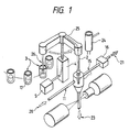
- the apparatus has a flow cell 1 to which are connected a pipe 11 for supplying the carrying liquid for sheath flow and an outlet pipe 15 for discharge of unused sample and washing fluid.
- a valve 16 opens and closes the passage through the pipe 15.
- a pipette 2 is mounted on an arm 25 to swing about a vertical axis and to be vertically moved with vertical movement of the arm 25.
- the pipette 2 is shown in two alternative positions, i.e. a discharge position at the cell 1 and a take-up position at a sample holder 3.
- the arm 25 is driven by a pipette driving device 4.
- Pick-up and discharge of liquid from the pipette is controlled by a syringe pump 5 through tubing.
- the arm 25 is rotatable further to a washing station 24 for the pipette 2.
- the apparatus has a plurality of sample holding containers 3 which are rotated to the sample pick-up position 26 in turn. See Fig. 10 for details of one possible arrangement of the sample supply apparatus.
- Fig. 2 shows in detail the connection of the pipette 2 to the flow cell 1 and the structure of the flow cell 1.
- the pipette is of inside diameter of 400 microns.
- the pipette 2 has a ring seal in the shape of a ball 6 on its exterior surface close to its lower end 19.
- the ball 6 is of resilient material, for example, rubber.
- Fig. 2 indicates that the pipette contains a sample fluid 17 and a transport fluid 18 which is used to move the sample fluid 17 into and out of the pipette.
- Fig. 2 also shows, the pipette 2 is received by an upwardly open bell-shaped mouth 7 of the flow cell 1.
- the mouth 7 narrows downwardly into a narrow passage 8 which ends at a nozzle 9.
- the mouth 7 and passage 8 constitute the input location of the flow cell 1.
- the nozzle 9 opens into a downwardly narrowing portion 12 of the detection passage of the flow cell.
- the carrying liquid for the sheath flow enters the upstream end of this narrowing portion 9 via the inlet 10 represented as part of the pipe 11.
- the flow of the carrying liquid is indicated by arrows 20.
- the narrow end of the narrowing portion 12 connects with the capillary detection portion 13 of constant cross section, which ends at an outlet 14, from which the discharge is represented by arrow 23.
- the flow of carrying liquid entrains the sample liquid emerging from the nozzle 9, which is accelerated by the contracting laminar flow of the carrier liquid in the portion 12 and forms a thin stream 22 in the detection portion 13.
- Fig. 1 illustrates how a detector is mounted to detect the passage of particles in the thin stream 22 in the detection portion 13 of the cell 1. As mentioned above, the principles of such sheath flow and the detection of particles in it is already known and need not be discussed further.
- Fig. 2 shows that the ball 6 forms a seal in the mouth 7 of the cell 1 when the pipette is inserted into the mouth 7.
- the connection of the pipe 15 into the mouth 7 is below, i.e. downstream of, the sealing point of the ball 6 in the mouth 7, in this embodiment.
- Liquid samples to be analysed are stored in each of the sample containers 3 and are sent to the sample sucking position 26 one at a time.
- the pipette 2 is lowered by the device 4 into the container 3 so that its tip is immersed in the sample liquid, and then a fixed amount of the sample 17 is sucked into the pipette 2 by the pump 5.
- the pipette 2 is raised and rotated into the position above the flow cell 1 and is slowly lowered.
- the carrying fluid 20 for sheath flow is continuously supplied to the flow cell and discharges through the outlet 14 via the capillary portion 13 and is also discharged through the discharge pipe 15 having passed by reverse flow through the nozzle 9 and the passage 8, in order to wash these parts.
- the valve 16 is open. In this way, any remaining traces of the previous sample analysed have been completely removed by the carrying liquid.
- the descending pipette 2 centres itself in the mouth 7 and the circumference of the ball 6 seals closely to the inner surface of the mouth 7 over its entire periphery.
- the downward force exerted by the driving device 4 is adjusted to achieve this sealing suitably.
- the valve 16 is closed immediately before close sealing of the ball 6 takes place so that the upper surface of the carrying fluid in the mouth 7 rises. Therefore, as the ball 6 becomes tightly sealed to the mouth 7 below the level of the surface of the carrying liquid, no air bubbles are formed in the passage 8.
- the pump 5 starts to cause discharge of the sample 17 at a predetermined rate.
- the sample is discharged from the nozzle 9 into the contracting region 12 and the sheath flow 22 of the sample is formed in the capillary region 13.
- the pipette After a predetermined amount or all of the sample fluid 17 has been pushed out of the pipette 2, the pipette is raised and removed from the inlet 7. At the same time, the valve 16 is opened and any residual fluid 17 is completely discharged via the discharge pipe 15. The pipette 2 is rotated and lowered into the washing tank 24 and thoroughly washed out by fluid discharge by the pump 5 and by washing water circulating in the washing tank, to wash the exterior of the pipette.
- a plurality of samples may be simultaneously stored in the sample containers 3 and may be held in readiness for analysis sequentially by the flow cell 1 and the detector. Furthermore, as described below, the samples may undergo preparation for analysis while in the containers 3, simultaneously.
- the pipette 2 moves the sample rapidly from the container 3 into the flow cell 1, and the sample is discharged into the flow cell close to the detection portion 13 immediately before flow takes place through the detection portion 13. Therefore, the time between passage of two adjacent samples in the sequence through the flow cell 1 is determined by the time taken by the movable pipette 2 to collect samples, deliver them at the flow cell and be washed. Washing of the flow cell takes place between delivery of the samples.
- the various samples held in the containers 3 may relate to the same original blood sample, and be prepared for different analysis in the flow cell, if the detector or detectors used so permit. Alternatively, there may be a plurality of samples from different patients, prepared for the same analysis in the flow cell.
- the arrangement of the outlet 15 from the sample input location permits very rapid and efficient washing of the residual sample from the flow cell.
- the sealing of the ball 6 and the inlet 7 of the flow cell avoids any leakage of sample, so that if desired the whole volume of the sample is passed into the capillary region 13. This means that substantially all the particles, e.g. blood cells, in the sample can be counted by the detector. If the dilution ratio of the sample, relative to the original blood sample, is known, the concentration of blood cells in the original sample can be calculated.
- the volume of the passage 8 is small. For example, it may be less than 5 microlitres, so that the sample 17 discharged from the pipette 2 rapidly reaches the nozzle 9. This minimises diffusion at the front and rear of the sample 17. Thus a uniform concentration of particles in the detector region 13 is rapdialy achieved and measurement time is minimized.
- a pipette to transfer the sample to the flow cell permits accurate delivery of predetermined quantities, e.g. 5 to 10 microlitres.
- This embodiment has been described particularly for counting of blood cell particles, but the invention is applicable to particle counting or analysis of particles in other ways generally. Thus it may be used for particle size detection, e.g. in analysis of liquid purity. It may be used to analyse, e.g. by counting, other biological cells, such as bacteria, as well as non-biological particles.
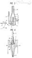
- Fig. 3 shows an embodiment in which the upper part of the passage 8 at the input location of the cell 1 is a flexible tube 27 of silicone rubber, connecting to the rigid mouth 7.
- the tube 27 can bend, so that the mouth 7 aligns with the descending position of the pipette 2 even if the pipette is lowered off the normal centre line of the mouth 7. This permits rapid insertion of the pipette 2 into the mouth.
- Fig. 4 shows an embodiment in which the pipette 2 includes a flexible portion 28 of silicone rubber, above the lowermost rigid portion. Again, the pipette 2 can rapidly align itself with the centre of the mouth 7 as it descends. Thus any positional inaccuracy of the pipette 2 is corrected, which enables rapid operation.
- the end portion of the pipette 2 has a bend 34 so that its tip extends horizontally, for a few mm at most.
- the mouth 7 receiving the pipette tube is also horizontal, and the orientation of the flow cell is upside down compared with that of Fig. 2.
- the flow of the carrying fluid and the sample is upwardly, and the pipette is moved horizontally in order to bring its discharge end into the mouth 7.
- Fig. 5 also shows an alternative form of pipette 2′, which, after having sucked the sample upwardly from a sample holder 3 is rotated as indicated by arrow 35 to a horizontal position, and then moved horizontally into the horizontal mouth 7 of the flow cell 1. This avoids the need for a bend 34 in the pipette.
- the mouth 7 opens downwardly, and the discharge pipe 15 of Fig. 2 is present.
- Fig. 6 illustrates a different form of resiliently deformable seal on the pipette 2.
- a rubber tube 37 grips the rigid portion of the tube 2 at its outlet end, and the tip 38 of the tube 37 is rolled back outwardly.
- the tube 37 makes sealing connection to the mouth 7 at the bend of this rolled portion 38.
- the length of the rolled portion 38 can be increased, i.e. the tube 37 rolled up a little further, as indicated by the arrow 36 by increase of the downward force of the pipette 2.
- deterioration of the rubber tube 37 caused by reagents in the sample fluids or by repeated operation can be dealt with by supplying a fresh region of surface for contact with the mouth 7, by the rolling up action described above. This improves the maintenance performance of the apparatus.
- the discharge port 14 of the flow cell is connected to a suction pump 49 through a pipe 50.
- the pipette 2 has no resilient seal and makes no contact with the mouth 7.
- the pipette 2 is moved to a position above the mouth 7 as indicated by the arrow 46 after sucking up the sample 17 and discharges the desired amount of the sample into the mouth 7.
- it is moved to the washing tank 24 as indicated by the arrow 47.
- the carrying fluid for the sheath flow is sucked through the cell by the suction pump 49, and therefore a negative pressure is formed in the contracting portion 12, and the sample now stored in the input location 7 is discharged from the nozzle 9 to form the sheath flow.
- the pipette 2 does not need to wait at the flow cell 1 while the flow of the sample through the flow cell is performed and can perform other operations, e.g. be washed and collect another sample, during the analysis of the previous sample.
- the average measurement time can be decreased.
- a nozzle 9 for discharge of the sample at the input location.
- the passage 8 contains a groove around it and a resilient O-ring 45 with an inside diameter slightly smaller than the outside diameter of the pipette tube 2 is lodged in this groove.
- the pipette itself is inserted through the O-ring 45, and forms the nozzle at its outlet end, which is located in the narrowing portion 12 of the cell 1.
- the carrying fluid 20 cannot leak here.
- the sheath flow 22 of the sample is formed at the capillary portion 13.
- the sheath flow of a desired uniform rate of the sample can be achieved extremely rapidly, and the measurement time reduced. Furthermore, by reason of the sheath flow, no part of the flow cell comes into contact with the sample, which reduces the need for washing, and avoids pollution of the flow cell by sample or reagent carry-over.
- the flow cell has an upwardly opening bell-shaped mouth 42 for inlet of the carrying liquid for the sheath flow.
- a passage 43 connects this inlet 42 with the narrowing portion 12.
- a movable tube 40 has a ball seal 41 at its lower end, like the pipette tube 2, and makes contact with the mouth 42 in the same way.
- the two tubes 2 and 40 are joined together so as to move in conjunction, under the action of the driving device 4.
- the pump for causing discharge of the carrying liquid from the tube 40 is provided.
- the carrying liquid may be brought into the tube 40 by sucking it upwardly through its discharge end, i. e. in the manner of a pipette.
- Carrying liquid specifically chosen for the particular sample in the pipette 2 can thus be quickly and easily simplified.
- the embodiment also allows a quick change of the flow cell since no fixed connection for the carrying liquid is required.
- a similar readily detachable connection for the output on the discharge port 14 can easily be arranged, so that there is no fixed connection to the flow cell. The flow cell is then easily exchanged, e.g. when a different detector is employed or for maintenance purposes.
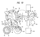
- Fig. 10 is a general view from above of apparatus embodying the invention, including means for preparing the samples for the particle analysis.
- a laser source 51 is indicated with a laser condenser lens 52 in front of it, and a fluoresence and scattered light detector lens 53 on the opposite side of the capillary portion of the flow cell 1.
- a light detector 54 is indicated beyond the lens 53 and a signal processor 55 is connected to the detector 54.
- a supply pump 56 for the carrying liquid is indicated, connected to the pipe 11.
- a tube 23 is shown for discharge of the waste fluid from the port 14 of the flow cell, connecting to a waste fluid bottle 57.
- the outlet pipe 15 for washing fluid and residual sample fluid is connected into the bottle 57.
- the sample holding containers 3, are mounted with equal spacing at positions 3-a to 3-h around the circumference of a rotatable reaction table 73.
- the position 3-a is the pick-up position for the pipette 2, which delivers the sample to the analysis cell 1.
- a stirring device consisting of a stirring arm 58 and a washing tank 60 for washing a stirring rod at the tip of the arm 58.
- the arm 58 is rotated and raised by a device 59.
- a reagent supplying device consisting of a rotatable arm 61 carrying a reagent pipette, with a driving device 62 for the arm and a syringe pump 63 for the pipette.
- a washing tank 65 for the reagent pipette along its arc of movement.
- Reagent bottles 64 are located around a reagent disc 66, and various reagents can be supplied to the samples by means of the reagent pipette by rotating the disc 66 to bring the desired sample into the position on the arc of movement of the reagent pipette, so that the reagent can be picked up and carried to the sample container.
- a sample supplying device for supplying samples to the sample holding containers 3 on the table 73.
- This sample supplying device has a rotatable arm 67 carrying a sample pipette, with a pipette driving device 69 and syringe pump 70 and a washing tank 68 for this pipette, as for the reagent supplying device and the pipette 2.
- a large number of sample cups 71 are mounted around the circumference of a sample disc 72, which rotates to bring the samples in turn to the location of the arc of movement of the sample pipette.
- a washing device 74 for washing the sample containers 3 is shown at the position 3-e to 3-h.
- the apparatus of Fig. 10 operates as follows.
- the sample pipette is moved to above one of the sample cups 71 by the sample pipette driver 69, is lowered into the sample cup and sucks up a predetermined amount of the sample.
- the sample pipette then moves to the sample holding container 3 at position 3-d of the reaction table 73 and discharges the predetermined amount of the sample.
- the sample pipette then moves to the washing tank 68 to be thoroughly washed.
- the reaction table 73 is rotated, to bring the container at 3-d to the next position 3-c.
- a predetermined amount of a desired reagent is added by the reagent pipette, which has collected the reagent from a reagent container 64 by an action similar to that of the sample pipette.
- the reaction table 73 is further rotated to bring the sample container now to the position 3-b.
- the contents of the container are stirred by the stirring device carried by the arm 58, and the desired reaction allowed to take place.
- the container 3 is rotated to the position 3-a, and a predetermined amount of the sample is supplied to the flow cell 1 by the pipette 2 carried by the arm 25. This action is repeated cyclically for each new sample. The cycles overlap, i.e. several samples may undergo treatment simultaneously. If the reaction time required after addition of the reagent at position 3-c and the stirring at position 3-b is longer than the rate at which it is desired to feed samples to the flow cell 1, an additional number of positions, at which the reaction is allowed to take place, can be provided on the reaction table. After the sample has been taken by the pipette 2 to the flow cell 1, the sample holding container is moved to the washing device 74, and surplus sample liquid is removed and the container thoroughly washed.
- the liquid sample supplied to the flow cell 1 is moved along the detection passage past the laser beam of the detector, and as desired the beam of scattered light and fluorescent light 76 is generated from the laser beam 75.
- the light 76 is captured by the detector 54 and desired information about the relevant particles is obtained at the signal processor 55.
- the samples are not conveyed by continuous tubes from the input to the apparatus to the reaction vessels and the flow cell. Thus there is no problem of pollution of such tubes by sample or reagent carry over.
- the absolute quantity of the samples and reagents required can be kept to the minimum.
- a plurality of samples can be undergoing preparation for analysis in the flow cell 1 simultaneously, and with great rapidity. This permits a very high rate of sample treatment, per hour.
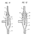
- the pipette mouth is a downwardly opening bell shape 29 while the passage 8 has an upward extension 30 of cylindrical shape carrying on its outer surface a rubber ring seal 31 of ball shape. Connection between the pipette and the passage 8 is made by bringing the mouth 29 of the pipette downwardly into contact with the ball 31. This provides a precise seal of the pipette to the flow cell.
- the end of the pipette 2 has the shape of a widened cylinder 32.
- the passage 8 has an upward extension 30, of cylindrical shape and having a circumferential groove in its outer surface, in which an O-ring 33 is located.
- the projection 30 is received in the cylindrical portion 32 of the pipette, and a good seal is achieved by the O-ring 8.
- the connection force of the pipette 2 to the flow cell 1 may be strong enough to allow the flow cell to be picked up by upward movement of the pipette 2, which allows the flow cell 1 to be lifted out for replacement.
- Figs. 13 and 14 show a flat flow cell 1 which can be made in the way described in EP-A-286088, EP-A-288029 and EP-A-294701.
- the pipette 2 used with this flow cell 1 is the same as in Fig. 2 and carries a ball seal 16, which makes sealing contact, as shown in Fig. 14, with a conical inlet mouth 7 of the cell, in the same manner as described above.
- the outlet passage 15 for residual sample and washing fluid opens to the mouth 7 above, i.e. upstream of, the sealing location of the ball 16, which contributes to improved washing of the mouth 7.
- connection 83 connects with the outlet passage 15 for the washing fluid and residual sample from the mouth 7. The fluid passing along the outlet passage 15 is sucked through the connection 83.
- the analysing light beam 90 and detector 91 are indicated in Fig. 13.
- the flow cell is very easily removed and replaced, e.g. when it is desired to change the type of analysis being performed by the apparatus.
- Fig. 15 this demonstrates the improved processing speed of samples which can be obtained with the present invention.
- the time zero of the horizontal axis represents the time at which the first portion of the sample fluid reaches the detection point in the flow cell, and the curves I and II indicate the rise of concentration of the detector to the steady state at which an approximately uniform concentration is present. This uniform concentration is given the value 1.0.
- the measuring time M required at this steady state is, in this example, about 10 seconds.
- the curve I is a typical result achieved for an analysis apparatus in which the sample is moved to the flow cell through a fixed tubing system, and it can be seen that the time taken to achieve the steady state at the detector is about 20 seconds. This applies for a tubing of length about 200 to 300 mm.
- the curve II is obtained, in which the rise to the steady state occupies about 2.5 seconds. Not only is there a great reduction in the total time required to process the sample in the flow cell, but also the required amount of each sample is reduced, compared with the prior art apparatus.
Landscapes
- Chemical & Material Sciences (AREA)
- General Health & Medical Sciences (AREA)
- Life Sciences & Earth Sciences (AREA)
- Health & Medical Sciences (AREA)
- Analytical Chemistry (AREA)
- Biochemistry (AREA)
- Physics & Mathematics (AREA)
- General Physics & Mathematics (AREA)
- Immunology (AREA)
- Pathology (AREA)
- Dispersion Chemistry (AREA)
- Automatic Analysis And Handling Materials Therefor (AREA)
- Optical Measuring Cells (AREA)
Applications Claiming Priority (2)
| Application Number | Priority Date | Filing Date | Title |
|---|---|---|---|
| JP63232462A JPH0718785B2 (ja) | 1988-09-19 | 1988-09-19 | フローセル装置 |
| JP232462/88 | 1988-09-19 |
Publications (3)
| Publication Number | Publication Date |
|---|---|
| EP0360487A2 true EP0360487A2 (de) | 1990-03-28 |
| EP0360487A3 EP0360487A3 (de) | 1991-07-24 |
| EP0360487B1 EP0360487B1 (de) | 1997-07-09 |
Family
ID=16939667
Family Applications (1)
| Application Number | Title | Priority Date | Filing Date |
|---|---|---|---|
| EP89309279A Expired - Lifetime EP0360487B1 (de) | 1988-09-19 | 1989-09-13 | Verfahren und Vorrichtung zur Bestimmung von in einer Flüssigkeitsprobe enthaltenen Teilchen |
Country Status (4)
| Country | Link |
|---|---|
| US (1) | US5079959A (de) |
| EP (1) | EP0360487B1 (de) |
| JP (1) | JPH0718785B2 (de) |
| DE (1) | DE68928157T2 (de) |
Cited By (20)
| Publication number | Priority date | Publication date | Assignee | Title |
|---|---|---|---|---|
| DE4209127A1 (de) * | 1991-03-20 | 1992-09-24 | Hitachi Ltd | Zellanalyseapparatur |
| EP0474187A3 (en) * | 1990-09-05 | 1992-10-14 | Hitachi, Ltd. | Particle measuring aparatus |
| EP0461618A3 (en) * | 1990-06-13 | 1992-11-25 | Becton Dickinson And Company | Cleaning cycle for flow cytometers |
| US5174162A (en) * | 1989-07-10 | 1992-12-29 | Hitachi, Ltd. | Pipetter, pipette tube, sample analyzing apparatus including them and method of mixing and pipetting liquids |
| EP0614077A3 (de) * | 1993-01-26 | 1995-03-08 | Hitachi Ltd | Durchflusszellenvorrichtung. |
| EP0645631A3 (de) * | 1993-09-29 | 1996-02-07 | Becton Dickinson Co | Vorrichtung zur Vorbereitung und Abgabe von Proben. |
| WO1996004544A1 (en) * | 1994-08-01 | 1996-02-15 | Abbott Laboratories | Method and apparatus for performing automated analysis |
| EP0729021A1 (de) * | 1995-02-25 | 1996-08-28 | Roche Diagnostics GmbH | Vorrichtung zur Bearbeitung von Proben auf Objektträgern |
| EP0687203A4 (de) * | 1993-03-05 | 1996-09-25 | William H Thompson | Gerät zum entleeren eines abschnitts einer blutprobe |
| EP0642025A4 (de) * | 1993-03-18 | 1997-02-26 | Daikin Ind Ltd | Messzeitkürzungsverfahren für messinstrumente. |
| US5631165A (en) * | 1994-08-01 | 1997-05-20 | Abbott Laboratories | Method for performing automated hematology and cytometry analysis |
| US5656499A (en) * | 1994-08-01 | 1997-08-12 | Abbott Laboratories | Method for performing automated hematology and cytometry analysis |
| EP0718619A3 (de) * | 1994-12-21 | 1998-05-13 | Toa Medical Electronics Co., Ltd. | Teilchenmessvorrichtung |
| EP0818674A3 (de) * | 1996-07-11 | 1998-07-29 | Gregory P. Harhay | Spektroskopisches Verfahren |
| US5891734A (en) * | 1994-08-01 | 1999-04-06 | Abbott Laboratories | Method for performing automated analysis |
| EP1271128A3 (de) * | 1994-08-01 | 2003-05-14 | Abbott Laboratories | Fluiddüse und Verfahren zum Einführen eines Fluids |
| CN1132870C (zh) * | 1996-02-07 | 2003-12-31 | 阿克奥化学技术公司 | 通过连续加入起始物进行双金属氰化物催化多醇的制备 |
| EP1056541A4 (de) * | 1998-02-27 | 2005-11-30 | Ventana Med Syst Inc | System und verfahren zum aufsaugen und zur abgabe eines reagenzes |
| US7396508B1 (en) | 2000-07-12 | 2008-07-08 | Ventana Medical Systems, Inc. | Automated molecular pathology apparatus having independent slide heaters |
| EP2397836A1 (de) * | 2010-05-06 | 2011-12-21 | Sony Corporation | Mikroteilchensortiervorrichtung, Mikrochip und Mikrochipmodul |
Families Citing this family (56)
| Publication number | Priority date | Publication date | Assignee | Title |
|---|---|---|---|---|
| US5408891A (en) * | 1992-12-17 | 1995-04-25 | Beckman Instruments, Inc. | Fluid probe washing apparatus and method |
| JP2763468B2 (ja) * | 1992-12-25 | 1998-06-11 | 株式会社日立製作所 | 光散乱を用いた液体内の粒子分類装置 |
| DE69532416T2 (de) * | 1994-10-14 | 2004-12-02 | University Of Washington, Seattle | Methode und vorrichtung zur tröpfchenerzeugung mit hoher rate bei der durchfluss-cytometrie |
| US5602039A (en) * | 1994-10-14 | 1997-02-11 | The University Of Washington | Flow cytometer jet monitor system |
| US5602349A (en) * | 1994-10-14 | 1997-02-11 | The University Of Washington | Sample introduction system for a flow cytometer |
| US6861265B1 (en) * | 1994-10-14 | 2005-03-01 | University Of Washington | Flow cytometer droplet formation system |
| US6454945B1 (en) * | 1995-06-16 | 2002-09-24 | University Of Washington | Microfabricated devices and methods |
| JPH09318522A (ja) * | 1996-05-29 | 1997-12-12 | Toa Medical Electronics Co Ltd | 粒子検出器及び粒子分析装置 |
| EP2264427B1 (de) | 1997-01-31 | 2017-05-03 | Xy, Llc | Optisches Gerät mit fokussierendem Reflektor zur Konvergenz der Strahlung auf einen Partikelfluss, und zugehöriges Analyseverfahren |
| US6159739A (en) * | 1997-03-26 | 2000-12-12 | University Of Washington | Device and method for 3-dimensional alignment of particles in microfabricated flow channels |
| US5819948A (en) * | 1997-08-21 | 1998-10-13 | Van Den Engh; Gerrit J. | Particle separating apparatus and method |
| US6071689A (en) * | 1997-12-31 | 2000-06-06 | Xy, Inc. | System for improving yield of sexed embryos in mammals |
| US6149867A (en) * | 1997-12-31 | 2000-11-21 | Xy, Inc. | Sheath fluids and collection systems for sex-specific cytometer sorting of sperm |
| US6248590B1 (en) | 1998-02-27 | 2001-06-19 | Cytomation, Inc. | Method and apparatus for flow cytometry |
| PT1917974E (pt) | 1998-07-30 | 2011-02-22 | Xy Llc | Sistema de inseminação artificial não cirúrgica em equinos |
| JP2000214070A (ja) * | 1999-01-21 | 2000-08-04 | Sysmex Corp | シ―スフロ―セルとそれを用いた血液分析装置 |
| US6228652B1 (en) | 1999-02-16 | 2001-05-08 | Coulter International Corp. | Method and apparatus for analyzing cells in a whole blood sample |
| US7024316B1 (en) | 1999-10-21 | 2006-04-04 | Dakocytomation Colorado, Inc. | Transiently dynamic flow cytometer analysis system |
| US7208265B1 (en) | 1999-11-24 | 2007-04-24 | Xy, Inc. | Method of cryopreserving selected sperm cells |
| IL152714A (en) | 2000-05-09 | 2014-03-31 | Xy Llc | High-purity spermatozoa populations carrying chromosome-x and chromosome-y |
| CN1633259A (zh) * | 2000-06-12 | 2005-06-29 | Xy公司 | 利用分离的带x-染色体和带y-染色体的精子群的综合兽群管理系统 |
| US20040031071A1 (en) * | 2000-10-05 | 2004-02-12 | Xy, Inc. | System of hysteroscopic insemination of mares |
| US7713687B2 (en) | 2000-11-29 | 2010-05-11 | Xy, Inc. | System to separate frozen-thawed spermatozoa into x-chromosome bearing and y-chromosome bearing populations |
| WO2002043486A1 (en) | 2000-11-29 | 2002-06-06 | Xy, Inc. | System for in-vitro fertilization with spermatozoa separated into x-chromosome and y-chromosome bearing populations |
| EP1395374B1 (de) | 2001-05-17 | 2013-04-17 | Beckman Coulter, Inc. | Durchflusszytometer mit aktivem automatisiertem optischem ausrichtungssystem |
| US20030211009A1 (en) * | 2001-05-18 | 2003-11-13 | Buchanan Kris S. | Rapid multi-material sample input system |
| DE20117914U1 (de) * | 2001-11-02 | 2003-03-13 | Evotec OAI AG, 22525 Hamburg | Probenabgabevorrichtung |
| JP4595067B2 (ja) | 2002-08-01 | 2010-12-08 | エックスワイ,エルエルシー | 低圧精子細胞分離システム |
| US8486618B2 (en) | 2002-08-01 | 2013-07-16 | Xy, Llc | Heterogeneous inseminate system |
| CA2534394C (en) * | 2002-08-15 | 2013-01-08 | Xy, Inc. | High resolution flow cytometer |
| US7169548B2 (en) * | 2002-09-13 | 2007-01-30 | Xy, Inc. | Sperm cell processing and preservation systems |
| BRPI0408857B1 (pt) | 2003-03-28 | 2018-09-11 | Inguran Llc | aparelho, métodos e processos para separar partículas e para prover esperma de animal separado por sexo |
| ES2541121T3 (es) | 2003-05-15 | 2015-07-16 | Xy, Llc | Clasificación eficiente de células haploides por sistemas de citometría de flujo |
| DK2801363T3 (en) | 2004-03-29 | 2018-05-28 | Inguran Llc | PROCEDURE FOR STORING SORTED SPERMATOZOES |
| US7621282B2 (en) * | 2004-06-17 | 2009-11-24 | Abbott Laboratories, Inc. | Probe washing cups and methods |
| CA2574499C (en) | 2004-07-22 | 2016-11-29 | Monsanto Technology Llc | Process for enriching a population of sperm cells |
| DK1771729T3 (en) * | 2004-07-27 | 2015-11-23 | Beckman Coulter Inc | Improving flowcytometridiskrimination using geometric transformation |
| US7340957B2 (en) | 2004-07-29 | 2008-03-11 | Los Alamos National Security, Llc | Ultrasonic analyte concentration and application in flow cytometry |
| US7618770B2 (en) * | 2005-07-29 | 2009-11-17 | Xy, Inc. | Methods and apparatus for reducing protein content in sperm cell extenders |
| US7835000B2 (en) | 2006-11-03 | 2010-11-16 | Los Alamos National Security, Llc | System and method for measuring particles in a sample stream of a flow cytometer or the like |
| US7867778B2 (en) * | 2007-02-23 | 2011-01-11 | Visiongate, Inc. | Fluid focusing for positional control of a specimen for 3-D imaging |
| EP2664916B1 (de) | 2007-04-02 | 2017-02-08 | Acoustic Cytometry Systems, Inc. | Verfahren zum Manipulieren einer Flüssigkeit in einer Durchflusszelle unter Anwendung von akustischer Fokussierung |
| US7837040B2 (en) * | 2007-04-09 | 2010-11-23 | Los Alamos National Security, Llc | Acoustic concentration of particles in fluid flow |
| US8083068B2 (en) | 2007-04-09 | 2011-12-27 | Los Alamos National Security, Llc | Apparatus for separating particles utilizing engineered acoustic contrast capture particles |
| US8263407B2 (en) | 2007-10-24 | 2012-09-11 | Los Alamos National Security, Llc | Method for non-contact particle manipulation and control of particle spacing along an axis |
| US8528406B2 (en) * | 2007-10-24 | 2013-09-10 | Los Alamos National Security, LLP | Method for non-contact particle manipulation and control of particle spacing along an axis |
| US8266951B2 (en) | 2007-12-19 | 2012-09-18 | Los Alamos National Security, Llc | Particle analysis in an acoustic cytometer |
| US8714014B2 (en) | 2008-01-16 | 2014-05-06 | Life Technologies Corporation | System and method for acoustic focusing hardware and implementations |
| US9103782B2 (en) | 2008-12-02 | 2015-08-11 | Malvern Instruments Incorporated | Automatic isothermal titration microcalorimeter apparatus and method of use |
| US8589851B2 (en) * | 2009-12-15 | 2013-11-19 | Memoir Systems, Inc. | Intelligent memory system compiler |
| CN103201634B (zh) * | 2010-10-27 | 2015-07-08 | 株式会社日立高新技术 | 自动分析装置 |
| JP2015222202A (ja) * | 2014-05-22 | 2015-12-10 | ソニー株式会社 | 粒子分析装置 |
| JP6592765B2 (ja) * | 2015-04-30 | 2019-10-23 | トライボテックス株式会社 | 粒子計数装置 |
| CN105973811A (zh) * | 2016-04-28 | 2016-09-28 | 江苏英诺华医疗技术有限公司 | 具有血液分析和生化分析功能的分析仪及方法 |
| CN109070148B (zh) * | 2016-05-11 | 2022-02-01 | 西门子医疗保健诊断公司 | 用于分析仪器的探针清洗站 |
| JP2024518755A (ja) | 2021-04-23 | 2024-05-02 | ベクトン・ディキンソン・アンド・カンパニー | 分析器及び/又は選別器式のフロー式粒子分析器用の流体管理システム |
Family Cites Families (27)
| Publication number | Priority date | Publication date | Assignee | Title |
|---|---|---|---|---|
| US3523733A (en) * | 1966-01-05 | 1970-08-11 | Technicon Corp | Method and apparatus for particle counting |
| CS151687B1 (de) * | 1968-04-09 | 1973-11-19 | ||
| AT278712B (de) * | 1968-04-30 | 1970-02-10 | H C Hans Dipl Ing Dr Dr List | Zusatzeinrichtung für die Mikroblutgasanalyse |
| US3583230A (en) * | 1968-06-12 | 1971-06-08 | Sondell Research Dev Co | Sample injection method and apparatus |
| US3661460A (en) * | 1970-08-28 | 1972-05-09 | Technicon Instr | Method and apparatus for optical analysis of the contents of a sheathed stream |
| US4290011A (en) * | 1978-05-18 | 1981-09-15 | Particle Data, Inc. | Particle length and volume comeasurement with controlled orientation |
| JPS54161388A (en) * | 1978-06-10 | 1979-12-20 | Toshiba Corp | Automatic chemical analyzer |
| US4202747A (en) * | 1978-07-06 | 1980-05-13 | Beckman Instruments, Inc. | Flow cell fluid and sample supply mechanism |
| JPS5535250A (en) * | 1978-09-06 | 1980-03-12 | Sumitomo Heavy Ind Ltd | Turbidimeter |
| IT1130926B (it) * | 1980-03-07 | 1986-06-18 | Erba Strumentazione | Dispositivo per il prelievo di campioni da analizzare,specialmente in capionatori automatici |
| GB2075672B (en) * | 1980-04-17 | 1983-03-09 | Chemlab Mfg Ltd | Washpot for use with sampling probe |
| US4367043A (en) * | 1980-05-05 | 1983-01-04 | Leland Stanford Junior University | Method and means for delivering liquid samples to a sample scanning device |
| JPS5782769A (en) * | 1980-11-10 | 1982-05-24 | Hitachi Ltd | Automatic analyzing device |
| DE3049565C2 (de) * | 1980-12-31 | 1985-05-30 | Max-Planck-Gesellschaft zur Förderung der Wissenschaften e.V., 3400 Göttingen | Vorrichtung zur Messung bestimmter Eigenschaften von in einer Partikelsuspension suspendierten Partikeln |
| JPS59107238A (ja) * | 1982-12-10 | 1984-06-21 | Hitachi Ltd | 光散乱を用いた粒子測定装置 |
| JPS59196440A (ja) * | 1983-04-23 | 1984-11-07 | Hiroaki Kimura | 血液自動分注方法及びその装置 |
| US4564803A (en) * | 1983-08-29 | 1986-01-14 | Coulter Corporation | Method and apparatus for removing foreign matter from a flow cell of a particle study device |
| NL8303440A (nl) * | 1983-10-07 | 1985-05-01 | Philips Nv | Doseerinrichting voor een meetvloeistof. |
| JPH0336914Y2 (de) * | 1985-05-17 | 1991-08-05 | ||
| JPS61270661A (ja) * | 1985-05-24 | 1986-11-29 | Hitachi Ltd | 自動分析装置における試料処理方法 |
| JPS61274242A (ja) * | 1985-05-30 | 1986-12-04 | Hitachi Electronics Eng Co Ltd | 微粒子検出装置 |
| US4790653A (en) * | 1986-05-22 | 1988-12-13 | Becton Dickinson And Company | Housing for a flow cytometry apparatus with particle unclogging feature |
| DE3773562D1 (de) * | 1986-07-11 | 1991-11-14 | Beckman Instruments Inc | Probenhandhabungsvorrichtung. |
| JP2564558B2 (ja) * | 1987-07-15 | 1996-12-18 | マツダ株式会社 | 車両用電装品制御装置 |
| US4917494A (en) * | 1987-07-28 | 1990-04-17 | Amherst Process Instruments, Inc. | Beam forming apparatus for aerodynamic particle sizing system |
| JP2761385B2 (ja) * | 1988-04-08 | 1998-06-04 | 東亜医用電子株式会社 | 免疫凝集測定装置 |
| US4914966A (en) * | 1988-12-15 | 1990-04-10 | R. J. Reynolds Tobacco Company | Automated ultrasonic probe holder for a sample feeder |
-
1988
- 1988-09-19 JP JP63232462A patent/JPH0718785B2/ja not_active Expired - Fee Related
-
1989
- 1989-09-08 US US07/404,559 patent/US5079959A/en not_active Expired - Lifetime
- 1989-09-13 DE DE68928157T patent/DE68928157T2/de not_active Expired - Lifetime
- 1989-09-13 EP EP89309279A patent/EP0360487B1/de not_active Expired - Lifetime
Cited By (25)
| Publication number | Priority date | Publication date | Assignee | Title |
|---|---|---|---|---|
| US5174162A (en) * | 1989-07-10 | 1992-12-29 | Hitachi, Ltd. | Pipetter, pipette tube, sample analyzing apparatus including them and method of mixing and pipetting liquids |
| EP0461618A3 (en) * | 1990-06-13 | 1992-11-25 | Becton Dickinson And Company | Cleaning cycle for flow cytometers |
| EP0474187A3 (en) * | 1990-09-05 | 1992-10-14 | Hitachi, Ltd. | Particle measuring aparatus |
| DE4209127A1 (de) * | 1991-03-20 | 1992-09-24 | Hitachi Ltd | Zellanalyseapparatur |
| EP0614077A3 (de) * | 1993-01-26 | 1995-03-08 | Hitachi Ltd | Durchflusszellenvorrichtung. |
| US5690895A (en) * | 1993-01-26 | 1997-11-25 | Hitachi, Ltd. | Flow cell apparatus |
| EP0687203A4 (de) * | 1993-03-05 | 1996-09-25 | William H Thompson | Gerät zum entleeren eines abschnitts einer blutprobe |
| EP0642025A4 (de) * | 1993-03-18 | 1997-02-26 | Daikin Ind Ltd | Messzeitkürzungsverfahren für messinstrumente. |
| EP0645631A3 (de) * | 1993-09-29 | 1996-02-07 | Becton Dickinson Co | Vorrichtung zur Vorbereitung und Abgabe von Proben. |
| WO1996004544A1 (en) * | 1994-08-01 | 1996-02-15 | Abbott Laboratories | Method and apparatus for performing automated analysis |
| US5891734A (en) * | 1994-08-01 | 1999-04-06 | Abbott Laboratories | Method for performing automated analysis |
| US5656499A (en) * | 1994-08-01 | 1997-08-12 | Abbott Laboratories | Method for performing automated hematology and cytometry analysis |
| EP1271128A3 (de) * | 1994-08-01 | 2003-05-14 | Abbott Laboratories | Fluiddüse und Verfahren zum Einführen eines Fluids |
| US5631165A (en) * | 1994-08-01 | 1997-05-20 | Abbott Laboratories | Method for performing automated hematology and cytometry analysis |
| US5939326A (en) * | 1994-08-01 | 1999-08-17 | Abbott Laboratories | Method and apparatus for performing automated analysis |
| EP0718619A3 (de) * | 1994-12-21 | 1998-05-13 | Toa Medical Electronics Co., Ltd. | Teilchenmessvorrichtung |
| US5830413A (en) * | 1995-02-25 | 1998-11-03 | Boehringer Mannheim Gmbh | Device for processing slide-mounted samples |
| EP0729021A1 (de) * | 1995-02-25 | 1996-08-28 | Roche Diagnostics GmbH | Vorrichtung zur Bearbeitung von Proben auf Objektträgern |
| CN1132870C (zh) * | 1996-02-07 | 2003-12-31 | 阿克奥化学技术公司 | 通过连续加入起始物进行双金属氰化物催化多醇的制备 |
| EP0818674A3 (de) * | 1996-07-11 | 1998-07-29 | Gregory P. Harhay | Spektroskopisches Verfahren |
| EP1056541A4 (de) * | 1998-02-27 | 2005-11-30 | Ventana Med Syst Inc | System und verfahren zum aufsaugen und zur abgabe eines reagenzes |
| EP2284543A2 (de) * | 1998-02-27 | 2011-02-16 | Ventana Medical Systems, Inc. | System und Verfahren zum Ansaugen und Ausgeben eines Reagenz |
| US7396508B1 (en) | 2000-07-12 | 2008-07-08 | Ventana Medical Systems, Inc. | Automated molecular pathology apparatus having independent slide heaters |
| EP2397836A1 (de) * | 2010-05-06 | 2011-12-21 | Sony Corporation | Mikroteilchensortiervorrichtung, Mikrochip und Mikrochipmodul |
| US8657121B2 (en) | 2010-05-06 | 2014-02-25 | Sony Corporation | Microparticle sorting apparatus, microchip and microchip module |
Also Published As
| Publication number | Publication date |
|---|---|
| JPH0280937A (ja) | 1990-03-22 |
| EP0360487A3 (de) | 1991-07-24 |
| JPH0718785B2 (ja) | 1995-03-06 |
| DE68928157D1 (de) | 1997-08-14 |
| US5079959A (en) | 1992-01-14 |
| EP0360487B1 (de) | 1997-07-09 |
| DE68928157T2 (de) | 1998-02-26 |
Similar Documents
| Publication | Publication Date | Title |
|---|---|---|
| US5079959A (en) | Analyzing system using sheath flow of sample | |
| US4683212A (en) | Random access single channel sheath stream apparatus | |
| US4888998A (en) | Sample handling system | |
| US3489525A (en) | System of automatic analysis | |
| JP3256818B2 (ja) | 試料液体分析装置及び試料液体分析法 | |
| US4526046A (en) | Method and apparatus for transferring a liquid sample | |
| JP3650126B2 (ja) | 自動血液分析システム及び血液スミアを作成する方法 | |
| US4366119A (en) | Discrete type automated chemical analytic apparatus | |
| JPH07185360A (ja) | 自動ピペット採取装置 | |
| JPH08178824A (ja) | 粒子測定装置 | |
| DK160730B (da) | Kontinuert stroemningsanlaeg for vaesker | |
| JPS62228952A (ja) | 自動化学分析装置における吸引吐出方法 | |
| US3876374A (en) | Method and apparatus for automated quantitative fluid analysis | |
| JPH04115136A (ja) | 粒子計測装置 | |
| US3401591A (en) | Analytical cuvette and supply system wherein the cuvette inlet and outlet are located on the bottom of the cuvette | |
| US4002269A (en) | Liquid proportioning system in a liquid sample analyzer | |
| EP0253519B1 (de) | Probenhandhabungsvorrichtung | |
| US6463969B1 (en) | Liquid sample dispensing methods for precisely delivering liquids without crossover | |
| JP3418329B2 (ja) | 試料分注方法及び自動分析装置 | |
| JP3665257B2 (ja) | 分注装置 | |
| JP2002031626A (ja) | 糖化ヘモグロビン分析計 | |
| JP2796352B2 (ja) | 粒子計数装置 | |
| JP3752653B2 (ja) | 試料希釈方法及び装置 | |
| JPH0756491B2 (ja) | 汚染防止容器およびそれを使用した分析装置 | |
| EP0112862B1 (de) | Verfahren und vorrichtung zum durchführen routinemässiger analysen, wie zum beispiel polarographischer oder spektrophotometrischer analysen |
Legal Events
| Date | Code | Title | Description |
|---|---|---|---|
| PUAI | Public reference made under article 153(3) epc to a published international application that has entered the european phase |
Free format text: ORIGINAL CODE: 0009012 |
|
| 17P | Request for examination filed |
Effective date: 19891030 |
|
| AK | Designated contracting states |
Kind code of ref document: A2 Designated state(s): DE GB |
|
| PUAL | Search report despatched |
Free format text: ORIGINAL CODE: 0009013 |
|
| AK | Designated contracting states |
Kind code of ref document: A3 Designated state(s): DE GB |
|
| 17Q | First examination report despatched |
Effective date: 19930728 |
|
| GRAG | Despatch of communication of intention to grant |
Free format text: ORIGINAL CODE: EPIDOS AGRA |
|
| GRAH | Despatch of communication of intention to grant a patent |
Free format text: ORIGINAL CODE: EPIDOS IGRA |
|
| GRAH | Despatch of communication of intention to grant a patent |
Free format text: ORIGINAL CODE: EPIDOS IGRA |
|
| GRAH | Despatch of communication of intention to grant a patent |
Free format text: ORIGINAL CODE: EPIDOS IGRA |
|
| GRAA | (expected) grant |
Free format text: ORIGINAL CODE: 0009210 |
|
| RBV | Designated contracting states (corrected) |
Designated state(s): DE |
|
| AK | Designated contracting states |
Kind code of ref document: B1 Designated state(s): DE |
|
| REF | Corresponds to: |
Ref document number: 68928157 Country of ref document: DE Date of ref document: 19970814 |
|
| PLBE | No opposition filed within time limit |
Free format text: ORIGINAL CODE: 0009261 |
|
| STAA | Information on the status of an ep patent application or granted ep patent |
Free format text: STATUS: NO OPPOSITION FILED WITHIN TIME LIMIT |
|
| 26N | No opposition filed | ||
| PGFP | Annual fee paid to national office [announced via postgrant information from national office to epo] |
Ref country code: DE Payment date: 20080908 Year of fee payment: 20 |