EP0362851A2 - Procédé de purification de métal liquide - Google Patents
Procédé de purification de métal liquide Download PDFInfo
- Publication number
- EP0362851A2 EP0362851A2 EP89118517A EP89118517A EP0362851A2 EP 0362851 A2 EP0362851 A2 EP 0362851A2 EP 89118517 A EP89118517 A EP 89118517A EP 89118517 A EP89118517 A EP 89118517A EP 0362851 A2 EP0362851 A2 EP 0362851A2
- Authority
- EP
- European Patent Office
- Prior art keywords
- pressure
- molten metal
- gas
- vessel
- torr
- Prior art date
- Legal status (The legal status is an assumption and is not a legal conclusion. Google has not performed a legal analysis and makes no representation as to the accuracy of the status listed.)
- Granted
Links
Images



Classifications
-
- C—CHEMISTRY; METALLURGY
- C22—METALLURGY; FERROUS OR NON-FERROUS ALLOYS; TREATMENT OF ALLOYS OR NON-FERROUS METALS
- C22B—PRODUCTION AND REFINING OF METALS; PRETREATMENT OF RAW MATERIALS
- C22B1/00—Preliminary treatment of ores or scrap
- C22B1/02—Roasting processes
- C22B1/04—Blast roasting
-
- C—CHEMISTRY; METALLURGY
- C21—METALLURGY OF IRON
- C21C—PROCESSING OF PIG-IRON, e.g. REFINING, MANUFACTURE OF WROUGHT-IRON OR STEEL; TREATMENT IN MOLTEN STATE OF FERROUS ALLOYS
- C21C7/00—Treating molten ferrous alloys, e.g. steel, not covered by groups C21C1/00 - C21C5/00
- C21C7/10—Handling in a vacuum
-
- C—CHEMISTRY; METALLURGY
- C21—METALLURGY OF IRON
- C21C—PROCESSING OF PIG-IRON, e.g. REFINING, MANUFACTURE OF WROUGHT-IRON OR STEEL; TREATMENT IN MOLTEN STATE OF FERROUS ALLOYS
- C21C7/00—Treating molten ferrous alloys, e.g. steel, not covered by groups C21C1/00 - C21C5/00
-
- C—CHEMISTRY; METALLURGY
- C21—METALLURGY OF IRON
- C21C—PROCESSING OF PIG-IRON, e.g. REFINING, MANUFACTURE OF WROUGHT-IRON OR STEEL; TREATMENT IN MOLTEN STATE OF FERROUS ALLOYS
- C21C7/00—Treating molten ferrous alloys, e.g. steel, not covered by groups C21C1/00 - C21C5/00
- C21C7/0081—Treating and handling under pressure
-
- C—CHEMISTRY; METALLURGY
- C22—METALLURGY; FERROUS OR NON-FERROUS ALLOYS; TREATMENT OF ALLOYS OR NON-FERROUS METALS
- C22B—PRODUCTION AND REFINING OF METALS; PRETREATMENT OF RAW MATERIALS
- C22B9/00—General processes of refining or remelting of metals; Apparatus for electroslag or arc remelting of metals
- C22B9/05—Refining by treating with gases, e.g. gas flushing also refining by means of a material generating gas in situ
Definitions
- the present invention relates to a method for cleaning molten metal, and more particularly to a method for obtaining clean molten metal by making nonmetallic inclusions rise to the surface of the molten metal and removing the nonmetallic inclusions from the molten metal.
- molten metal under elevated pressure is bubbled by a gas soluble in the molten metal, inclusions being suspended in the molten metal are trapped by gas bubbles produced by bubbling and by fine gas bubbles produced by reducing the pressure on pressurized molten metal. After the inclusions have risen to the surface of the molten metal, said inclusions are removed. Ordinary inclusions are trapped by first bubbling. Said trapped inclusions rise to the surface of the molten steel. On the other hand, since pressurized molten metal is bubbled, a large amount of bubbling gas dissolves in the molten metal.
- gas having dissolved in the molten metal appears as fine gas bubbles from the entire zone of the molten metal by rapidly reducing a pressure inside a vessel. During the bubbling, the fine inclusions are trapped by the bubbles and rise to the surface of the molten metal with the bubbles.
- the above-mentioned method is very effective in removal of the inclusions in the molten metal.
- the molten metal is pressurized at the initial stage of a processing step, some portion of the bubbling gas having once dissolved in the molten metal appears as fine gas bubbles during the reduction of the pressure on the molten metal, but the rest of the gas remains dissolved in the molten metal. Accordingly, one more processing step for degassing the molten metal is required after the above-mentioned processing of the gas has been carried out. Therefore, there have been problems in that degassing capacity and the number of processing steps had to be increased. In addition, a cost for equipment increased because of the use of a pressure vessel.
- the present invention provides a method for cleaning molten metal comprising the steps of: keeping a pressure inside a vessel having molten metal therein at a pressure of P S of atmospheric pressure or less; bubbling the molten metal in the vessel by gas soluble in the molten metal, a portion of said gas dissolving in the molten metal and the rest of said gas converting to gas bubbles; and reducing rapidly the pressure in the vessel to pressure P E , fine gas bubbles being produced in the molten metal in the vessel, nonmetallic inclusions being trapped by said fine gas bubbles and by gas bubbles produced by bubbling and rising to the surface of the molten metal, and gas dissolved in the molten metal being removed.
- the molten metal is not processed under elevated pressure as in the prior art method.
- the molten metal is processed under reduced pressure after the molten metal has been bubbled by blowing gas soluble in the molten metal at atmospheric pressure or less.
- this processing under reduced pressure not only the fine gas bubbles are simply produced, but also said bubbling gas remaining dissolved in the molten metal is removed together with the fine gas bubbles.
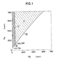
- Fig.1 shows a result of having studied the case when molten steel was used as molten metal and nitrogen as gas soluble in the molten steel.
- Fig.1 is a graphical representation designating preferable zones out of coordinates of pressure P S of atmosphere inside a vessel, under which the molten metal is bubbled by blowing said gas into the molten metal, and of reduced pressure P E of atmosphere inside the vessel. Units of P S and P E are Torr.
- Zone B shown with oblique lines is a preferable zone.
- Zone A shown with crossing lines is more preferable zone.
- the zone B is a zone where the inclusions decrease.
- a denitrification step is sometimes required after processing of the molten steel under reduced pressure.
- Units of [N ] and P N are ppm and atm, respectively.
- the allowable largest value of [N] is estimated at 100 ppm.
- [N ] ⁇ 100 is obtained.
- [ N ] ⁇ 100 is substituted for the equation (1) and the pressure unit is converted from atm to Torr, P N ⁇ 38 Torr is obtained.
- P E 40 Torr is obtained by rounding P N ⁇ 38 Torr.
- the amount of nitrogen removed from the molten steel which was required for trapping the inclusions and making the inclusions rise to the surface of the molten steel needed to be 50 ppm or more by experience of the present inventors.
- the amount of removed nitrogen is the difference between [N ] S and [N ] E.
- [N ] s is the initial content of nitrogen increased by bubbling the molten steel by blowing nitrogen into the molten steel.
- [N] E is the final content of nitrogen decreased by degassing the molten steel under reduced pressure.
- P E is less than 75 Torr in the equation (1), it takes much time to make an equilibrium state between the pressure P N and the content [N ] and this is ineffective.
- P E of less than 75 Torr is considered difficult to apply.
- the line 3 passing the lower ends of the zone A was determined by connecting the point ( 0, 75 ) with the point ( 40, 88 ).
- More preferable zone A is two-dimensional rectangular coordinates, whose ordinate is P S Torr and whose abscissa is P E Torr.
- the preferable zone B is two-dimensional rectangular coordinates, whose ordinate is P S Torr and whose abscissa is P E .
- Fig.2 is a vertical sectional view illustrating a refining apparatus for a ladle having been used for the example of the present invention.
- referential numeral 30 denotes a gas tight vessel.
- Ladle 32 of 50 ton capacity, into which molten steel 31 is charged, is put into the vessel.
- Cover 33 of the gas tight vessel 30 is arranged in a removable state Lance 34 is fixed to the cover to be used for VOD ( Vacuum Oxygen Decarbonization ).
- Referential numeral 36 denotes an exhaust opening for making the gas tight vessel vacuum.
- Referential numeral 36 denotes a porous plug for blowing gas into the molten steel, which is arranged at the bottom of the ladle.
- Example-2 The content of the molten steel obtained by processing of the molten steel in said Example-1 will be shown in Table 1.
- Example-2 shown in this Table will be described later.
- Results obtained in the case of using the prior art pressure elevation and reduction method ( Control-1 ) wherein molten steel was degassed under reduced pressure after the molten steel had been bubbled by N2 gas under elevated pressure of more than atmospheric pressure and an Ar gas bubbling method ( Control-2 ) are shown as controls in Table 1.
- the pressure in the vessel was increased to 3 atm during blowing of N2 gas and then reduced to 100 Torr during reduction of the pressure.
- Ar gas was not blown into the molten steel during pressure reduction.
- Example-1 0 0.13 0.32 1.12 0.023 0.006 0.048 42 147 10 0.13 0.31 1.12 0.023 0.006 0.047 8 38 20 0.13 0.31 1.12 0.023 0.006 0.047 7 31
- Example-2 0 0.14 0.33 1.14 0.021 0.005 0.049 42 147 10 0.14 0.32 1.13 0.021 0.005 0.047 7 60 20 0.14 0.32 1.13 0.021 0.005 0.047 5 35
- Control-1 Pressure Elevation and Reduction Method 0 0.13 0.33 1.13 0.020 0.005 0.050 41 632 10 0.13 0.32 1.13 0.020 0.005 0.048 9 279 20 0.13 0.32 1.13 0.020 0.005 0.047 9 162
- Control-2 Ar Gas Bubbling Method 0 0.12 0.33 1.15 0.018 0.005 0.054 42 20 10 0.12 0.32 1.14 0.018 0.005 0.054 24 19 20 0.12 0.31 1.15 0.018 0.005 0.052 18 18
- Example-1 when Example-1 is compared with Control-1 or Control-2 relative to the total amount of oxygen T.[O] and the total amount of nitrogen T.[N] in the molten steel 20 min later after the pressure reduction,T.[O] in Example-1 decreased and T.[N] greatly decreased in comparison with the pressure elevation and reduction method. In comparison with the Ar gas bubbling method, it is recognized that T.[O] decreased. In this case, the amount of nitrogen increased slightly by blowing nitrogen gas, but such T.[N] does not pose any specific problem except for specific cases.
- Example-2 When the molten steel is stirred by blowing inert gas into the molten steel under reduced pressure as in the Example-1, soluble gas is remarkably removed from the molten steel and the amount of nitrogen decreased to the extent enough to be able to be put to practical use inspite of bubbling of the soluble gas in comparison with Control-1 and Control-2 in Table 1.
- the soluble gas however, is removed during the pressure reduction and, at the same time, the occurrence of fine gas bubbles is also decreased. Accordingly, it is thought that the effect of rising and separation of nonmetallic inclusions decreases with the lapse of time. Therefore, it is intended in Example-2 to keep the effect of the rising and separation of the nonmetallic inclusions by blowing the soluble gas together with the inert gas during the pressure reduction.
- Example-1 a refining apparatus for a ladle as shown in Figs.2 and 3 was used. Soluble gas was blown into molten steel before a pressure reduction, 50 t of molten steel being kept at 1660°C and at 300 Torr. 6 Nm3 of N2 gas was blown from the bottom of the ladle as shown in Fig.2 into the molten steel by means of a porous plug for 10 min. Then, cover 33 was changed for cover 38. Heat compensation was made for the molten steel by the use of arc heat of electrodes. Pressure in the ladle was rapidly reduced to 1 Torr and the pressure of 1 Torr was kept for 20 min.
- the molten steel was bubbled by blowing Ar gas as inert gas together with N2 gas from the bottom of the ladle at a rate of 150 Nl/min. Flow of N2 gas was decreased to zero in the last five minutes as shown in Table 2 so as to make the amount of soluble gas as small as possible.
- Table 2 Time after Pressure Reduction 0 ⁇ 10 10 ⁇ 15 15 ⁇ 20 Amount of Gas Blown into Molten Steel Nl/min Ar 100 30 150 N2 50 120 0
- Example-2 The components of molten steel which were obtained as a result of having processed the molten steel in Example-2 will be shown in Table 1.
- T.[O] was decreased by blowing nitrogen into the molten steel under reduced pressure while T.[N] was increased slightly.
- the soluble gas is removed by pressure reduction in Preferred Embodiment-1 and Preferred Embodiment-2.
- a static pressure in a bottom portion of the molten metal bath becomes large.
- the depth of the molten steel is 1.5 m or more, the above- mentioned tendency became remarkable.
- Fig.4 shows an example of a gas tight vessel 1 being able to be tuned upside down with horizontal rotaton axis in a central portion thereof.
- Said gas tight vessel 1 is made cylindrical by tightly jointing vessel 1A and vessel 1b , each of which has a form of a ladle of 2 m in diameter and 3 m in height.
- Gas blow opening 11 is positioned on an end face of the vessel 1b. Exhaust opening for exhausting an atmospheric gas from vessel 1 is arranged in joint portion 13 of the vessels 1a and 1b.
- molten steel was cleaned by the use of the gas tight vessel 1 constituted with the vessels 1a and 1b as described above. 50 t of molten steel 31 was charged into the vessel 1b. Another vessel 1a was tightly jointed to the vessel 1b from above to form the vessel 1. Then, N2 gas was blown into the vessel 1 through the gas blow opening 11 at a rate of 100 N l/min to bubble the molten steel 31. Gas was exhausted from the vessel 1 through said gas exhaust opening 12 so that the pressure inside the gas tight vessel 1 could not exceed a predetermined pressure. 20 minutes later, bubbling was stopped.
- the gas tight vessel was turned counterclockwise at 180 ° as shown in Fig.5 and was made to be in the upsidedown state as shown in Fig.4. Since a portion of the molten steel bath which had been in a deep position and had been under large static pressure was changed for a portion of molten steel bath of small depth, a static pressure decreased rapidly and a large amount of fine gas bubbles were produced from the portion of the molten steel bath of small depth. After the molten steel had been left in this state for 5 minutes, the gas tight vessel was turned clockwise at 180° to be again in the state of Fig.4. In this case, the molten steel 31 was again stirred.
- Fig.6 shows a change of the total amount of oxygen in the molten steel 31 with the lapse of time in the example. According to Fig.6, the total amount of oxygen in the molten steel could be decreased from initial 80 ppm to final 12 ppm.
- Example-3 An apparatus used for this method was the apparatus having been used in Example-3 as shown in Fig.4.
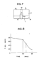
- Example-3 after molten steel had been kept in the gas tight vessel 1 and bubbled by blowing N2 gas into the molten steel through gas blow opening 11 positioned in the bottom of the vessel 1, pressure inside the gas tight vessel was reduced to 10 ⁇ 2 Torr by evacuating the gas tight vessel and the vacuum was kept. After the degree of vacuum had been kept for 5 min, the gas tight vessel 1 was turned at 90° with central horizontal rotation axis 10 in a central portion thereof. The gas tight vessel 1 came to be in the state such that a longitudinal direction of the gas tight vessel of cylindrical shape was kept horizontally.
- Fig.8 is a graphical representation designating a change of the total amount of oxygen T.[O] in the molten steel 31 which was processed by the above-mentioned degassing method wherein the depth of the molten steel bath was made small. As shown in Fig.8, it is understood that the degassing method is highly effective in processing of the molten steel since T.[O] in the molten steel was decreased from initial 80 ppm to final 15 ppm. In Example-3 wherein the gas tight vessel 1 was turned to 180° , when rotation of the gas tight vessel 1 was stopped for a while at the position where the vessel was turned to 90 ° , the effect of turning the gas tight vessel 1 at 180° and 90 ° can be obtained.
- Fig.9 is a schematic illustration showing another example of a method for promoting degassing of molten steel by making a depth of molten steel bath small.
- gas tight vessel 2 of parallelepiped of 3 m in width, 3 m in height and 8 m in length was used.
- Removable gate 3 of 3 m in length, 2.3 m in width and 0.5 m in thickness was arranged inside the gas tight vessel 2.
- the inside of the gas tight vessel 2 was divided into two chambers 2a and 2b.
- referential numeral 22 denotes an exhaust opening for exhausting inside atmosphere which is arranged in a ceiling of the gas tight vessel 2, 21 a gas injection opening arranged in the bottom of the chamber 2a, 23 an exit port for outflow of the molten steel which is arranged in the bottom of the chamber 2b and 24 an inlet for inflow of the molten steel which is arranged in a ceiling of the chamber 2a.
- Said gas injection opening 21 and said inlet for inflow of the molten steel are arranged so that they can be opened for closed if necessary.
- FIG.9 A method for cleaning molten steel by the use of the gas tight vessel 2 constituted in such a manner as described above will be described.
- gate 3 is positioned 2 m away from the left face of the gas tight vessel 2.
- Approximately 90 t of molten steel 31 is charged through the inlet 23 for inflow of the molten steel into one chamber 2a separated from the other chamber 2b by the gate 3.
- the exit port 23 for outflow of the molten steel is closed.
- the volume of the molten steel 31 comes to be 12 m3 of 3 m in length, 2 m in width and 2 m in depth.
- N2 gas is blown through the gas blow opening 21 at a rate of 100 N l/min and the molten steel 3 is bubbled by N2 gas.
- the inside atmosphere is simultaneously exhausted through said gas exhaust opening 22 so that there cannot be any excessive pressure inside the gas tight vessel.
- the bubbling of the molten steel is stopped 20 minutes later and the inside of the gas tight vessel 2 is evacuated through said gas exhaust opening 22 by the use of a vacuum pump (not shown ).
- An opening is made between the bottom face and the lower ends of the gate 3 by lifting the gate 3 upwardly as shown in Fig.10 when the pressure inside the gas tight vessel 2 is reduced to 10 ⁇ 2 Torr.
- the molten steel having been stemmed by said gate 3 spreads in the whole vessel 2.
- the depth of the molten steel 31 having been 2 m initially comes to be 0.5 m.
Landscapes
- Chemical & Material Sciences (AREA)
- Engineering & Computer Science (AREA)
- Materials Engineering (AREA)
- Metallurgy (AREA)
- Organic Chemistry (AREA)
- Manufacturing & Machinery (AREA)
- Mechanical Engineering (AREA)
- Life Sciences & Earth Sciences (AREA)
- Environmental & Geological Engineering (AREA)
- General Life Sciences & Earth Sciences (AREA)
- Geochemistry & Mineralogy (AREA)
- Geology (AREA)
- Treatment Of Steel In Its Molten State (AREA)
- Casting Support Devices, Ladles, And Melt Control Thereby (AREA)
- Manufacture And Refinement Of Metals (AREA)
Applications Claiming Priority (6)
| Application Number | Priority Date | Filing Date | Title |
|---|---|---|---|
| JP250807/88 | 1988-10-06 | ||
| JP250806/88 | 1988-10-06 | ||
| JP63250807A JPH0742524B2 (ja) | 1988-10-06 | 1988-10-06 | 溶融金属の清浄化方法 |
| JP25080688A JP2718096B2 (ja) | 1988-10-06 | 1988-10-06 | 溶融金属の減圧清浄化方法 |
| JP1031105A JPH02211974A (ja) | 1988-01-21 | 1989-02-13 | 溶融金属の減圧清浄化方法 |
| JP31105/89 | 1989-02-13 |
Publications (3)
| Publication Number | Publication Date |
|---|---|
| EP0362851A2 true EP0362851A2 (fr) | 1990-04-11 |
| EP0362851A3 EP0362851A3 (en) | 1990-06-20 |
| EP0362851B1 EP0362851B1 (fr) | 1993-03-31 |
Family
ID=27287204
Family Applications (1)
| Application Number | Title | Priority Date | Filing Date |
|---|---|---|---|
| EP89118517A Expired - Lifetime EP0362851B1 (fr) | 1988-10-06 | 1989-10-05 | Procédé de purification de métal liquide |
Country Status (6)
| Country | Link |
|---|---|
| EP (1) | EP0362851B1 (fr) |
| KR (1) | KR920006578B1 (fr) |
| AU (2) | AU4245789A (fr) |
| BR (1) | BR8905068A (fr) |
| CA (1) | CA1339703C (fr) |
| DE (1) | DE68905741T2 (fr) |
Cited By (1)
| Publication number | Priority date | Publication date | Assignee | Title |
|---|---|---|---|---|
| GB2240499A (en) * | 1990-02-05 | 1991-08-07 | Labate Michael D | Method for producing clean steel for continuous casting |
Family Cites Families (6)
| Publication number | Priority date | Publication date | Assignee | Title |
|---|---|---|---|---|
| FR1582780A (fr) * | 1968-01-10 | 1969-10-10 | ||
| US3635696A (en) * | 1968-05-21 | 1972-01-18 | Finkl & Sons Co | Treatment of molten metal using arc heat and vacuum |
| DE2710577A1 (de) * | 1977-03-11 | 1978-09-14 | Thyssen Edelstahlwerke Ag | Verfahren zum frischen von stahl |
| DE3426736A1 (de) * | 1984-07-20 | 1986-01-30 | Klöckner CRA Technologie GmbH, 4100 Duisburg | Verfahren zur spuelgasbehandlung von metallschmelzen |
| GB2162604B (en) * | 1984-07-30 | 1988-05-25 | Teves Gmbh Alfred | Braking pressure generator for a hydraulic brake system |
| US4780134A (en) * | 1986-09-23 | 1988-10-25 | A. Finkl & Sons Co. | Simplified method and apparatus for treating molten steel |
-
1989
- 1989-09-29 CA CA000614559A patent/CA1339703C/fr not_active Expired - Fee Related
- 1989-10-02 AU AU42457/89A patent/AU4245789A/en not_active Abandoned
- 1989-10-05 DE DE8989118517T patent/DE68905741T2/de not_active Expired - Fee Related
- 1989-10-05 BR BR898905068A patent/BR8905068A/pt not_active IP Right Cessation
- 1989-10-05 EP EP89118517A patent/EP0362851B1/fr not_active Expired - Lifetime
- 1989-10-06 KR KR1019890014420A patent/KR920006578B1/ko not_active Expired
-
1992
- 1992-04-02 AU AU13976/92A patent/AU655245B2/en not_active Ceased
Cited By (2)
| Publication number | Priority date | Publication date | Assignee | Title |
|---|---|---|---|---|
| GB2240499A (en) * | 1990-02-05 | 1991-08-07 | Labate Michael D | Method for producing clean steel for continuous casting |
| GB2240499B (en) * | 1990-02-05 | 1993-08-11 | Labate Michael D | Method for producing clean steel |
Also Published As
| Publication number | Publication date |
|---|---|
| AU655245B2 (en) | 1994-12-08 |
| EP0362851A3 (en) | 1990-06-20 |
| CA1339703C (fr) | 1998-03-10 |
| KR920006578B1 (ko) | 1992-08-10 |
| DE68905741D1 (de) | 1993-05-06 |
| KR900006541A (ko) | 1990-05-08 |
| AU1397692A (en) | 1992-05-28 |
| AU4245789A (en) | 1990-08-16 |
| BR8905068A (pt) | 1990-05-08 |
| EP0362851B1 (fr) | 1993-03-31 |
| DE68905741T2 (de) | 1993-09-23 |
Similar Documents
| Publication | Publication Date | Title |
|---|---|---|
| EP0347884A2 (fr) | Procédé pour le dégazage et la décarburation sous vide avec compensation de la baisse de la température | |
| US4714104A (en) | Method of continuously casting a metal and an apparatus for continuously casting the same | |
| EP0362851B1 (fr) | Procédé de purification de métal liquide | |
| CA1238788A (fr) | Methode et dispositif d'affinage du metal en fusion | |
| CA1338397C (fr) | Methode d'affinage sous vide de l'acier en fusion | |
| US5891215A (en) | Molten metal degassing and filtering methods | |
| US5091000A (en) | Method for cleaning molten metal and apparatus therefor | |
| JPH05271748A (ja) | 真空脱ガス方法 | |
| KR930005065B1 (ko) | 용융금속의 청정화방법 및 그 장치 | |
| JPH0299263A (ja) | 溶融金属の減圧清浄化方法 | |
| JPH0610027A (ja) | 溶融金属用真空脱ガス精錬方法 | |
| KR100226917B1 (ko) | 투피스캔용 고청정강의 제조방법 | |
| JPH06299227A (ja) | Rh式脱ガス装置による極低炭素鋼の製造方法 | |
| JP2718097B2 (ja) | 二段重ね容器を用いた溶融金属の減圧清浄化方法 | |
| JPS62202070A (ja) | 溶融メツキ金属の介在物除去方法 | |
| JPS5925919A (ja) | 溶鋼に蒸気圧の高い添加元素を添加する方法 | |
| JPH0610028A (ja) | 極低炭素鋼の製造方法 | |
| IE902105L (en) | A method of and an apparatus for degassing and maintaining a¹low hydrogen content in liquid aluminium alloys while they¹are being carried in ladles | |
| JPH01284476A (ja) | 溶融金属の清浄化装置 | |
| JPH0610029A (ja) | 極低炭素鋼の製造方法 | |
| JPH02270908A (ja) | 溶融金属の清浄化方法 | |
| JPH0860231A (ja) | 溶鋼の高清浄化方法 | |
| JPH07185772A (ja) | 溶湯処理装置 | |
| JPH05320739A (ja) | 真空精錬方法 | |
| JPS61288008A (ja) | 二次精錬方法及び装置 |
Legal Events
| Date | Code | Title | Description |
|---|---|---|---|
| PUAI | Public reference made under article 153(3) epc to a published international application that has entered the european phase |
Free format text: ORIGINAL CODE: 0009012 |
|
| 17P | Request for examination filed |
Effective date: 19891005 |
|
| AK | Designated contracting states |
Kind code of ref document: A2 Designated state(s): DE FR GB IT |
|
| PUAL | Search report despatched |
Free format text: ORIGINAL CODE: 0009013 |
|
| AK | Designated contracting states |
Kind code of ref document: A3 Designated state(s): DE FR GB IT |
|
| 17Q | First examination report despatched |
Effective date: 19920619 |
|
| GRAA | (expected) grant |
Free format text: ORIGINAL CODE: 0009210 |
|
| AK | Designated contracting states |
Kind code of ref document: B1 Designated state(s): DE FR GB IT |
|
| ITF | It: translation for a ep patent filed | ||
| REF | Corresponds to: |
Ref document number: 68905741 Country of ref document: DE Date of ref document: 19930506 |
|
| ET | Fr: translation filed | ||
| PLBE | No opposition filed within time limit |
Free format text: ORIGINAL CODE: 0009261 |
|
| STAA | Information on the status of an ep patent application or granted ep patent |
Free format text: STATUS: NO OPPOSITION FILED WITHIN TIME LIMIT |
|
| 26N | No opposition filed | ||
| REG | Reference to a national code |
Ref country code: GB Ref legal event code: IF02 |
|
| PGFP | Annual fee paid to national office [announced via postgrant information from national office to epo] |
Ref country code: GB Payment date: 20031001 Year of fee payment: 15 |
|
| PGFP | Annual fee paid to national office [announced via postgrant information from national office to epo] |
Ref country code: FR Payment date: 20031003 Year of fee payment: 15 |
|
| PGFP | Annual fee paid to national office [announced via postgrant information from national office to epo] |
Ref country code: DE Payment date: 20031016 Year of fee payment: 15 |
|
| PG25 | Lapsed in a contracting state [announced via postgrant information from national office to epo] |
Ref country code: GB Free format text: LAPSE BECAUSE OF NON-PAYMENT OF DUE FEES Effective date: 20041005 |
|
| PG25 | Lapsed in a contracting state [announced via postgrant information from national office to epo] |
Ref country code: DE Free format text: LAPSE BECAUSE OF NON-PAYMENT OF DUE FEES Effective date: 20050503 |
|
| GBPC | Gb: european patent ceased through non-payment of renewal fee |
Effective date: 20041005 |
|
| PG25 | Lapsed in a contracting state [announced via postgrant information from national office to epo] |
Ref country code: FR Free format text: LAPSE BECAUSE OF NON-PAYMENT OF DUE FEES Effective date: 20050630 |
|
| REG | Reference to a national code |
Ref country code: FR Ref legal event code: ST |
|
| PG25 | Lapsed in a contracting state [announced via postgrant information from national office to epo] |
Ref country code: IT Free format text: LAPSE BECAUSE OF NON-PAYMENT OF DUE FEES;WARNING: LAPSES OF ITALIAN PATENTS WITH EFFECTIVE DATE BEFORE 2007 MAY HAVE OCCURRED AT ANY TIME BEFORE 2007. THE CORRECT EFFECTIVE DATE MAY BE DIFFERENT FROM THE ONE RECORDED. Effective date: 20051005 |