EP0364404A2 - Appareil et méthode pour réparer automatiquement les fils de chaînes cassés dans les métiers à tisser - Google Patents
Appareil et méthode pour réparer automatiquement les fils de chaînes cassés dans les métiers à tisser Download PDFInfo
- Publication number
- EP0364404A2 EP0364404A2 EP89810752A EP89810752A EP0364404A2 EP 0364404 A2 EP0364404 A2 EP 0364404A2 EP 89810752 A EP89810752 A EP 89810752A EP 89810752 A EP89810752 A EP 89810752A EP 0364404 A2 EP0364404 A2 EP 0364404A2
- Authority
- EP
- European Patent Office
- Prior art keywords
- reed
- drop wire
- mentioned
- broken
- thread
- Prior art date
- Legal status (The legal status is an assumption and is not a legal conclusion. Google has not performed a legal analysis and makes no representation as to the accuracy of the status listed.)
- Granted
Links
- 238000009941 weaving Methods 0.000 title claims abstract description 68
- 238000000034 method Methods 0.000 title claims description 6
- 235000014676 Phragmites communis Nutrition 0.000 claims abstract description 91
- 210000000056 organ Anatomy 0.000 claims abstract description 33
- 229910000831 Steel Inorganic materials 0.000 claims abstract description 29
- 239000010959 steel Substances 0.000 claims abstract description 29
- 239000004744 fabric Substances 0.000 claims abstract description 26
- 238000012545 processing Methods 0.000 claims abstract description 8
- 238000000926 separation method Methods 0.000 claims abstract description 4
- 230000008439 repair process Effects 0.000 claims description 43
- 238000006073 displacement reaction Methods 0.000 claims description 11
- 238000005520 cutting process Methods 0.000 claims description 9
- 230000005693 optoelectronics Effects 0.000 claims description 9
- 238000005304 joining Methods 0.000 claims description 6
- 239000000463 material Substances 0.000 claims description 5
- 230000000295 complement effect Effects 0.000 claims 2
- 238000005259 measurement Methods 0.000 claims 1
- 230000000875 corresponding effect Effects 0.000 abstract description 25
- 230000000717 retained effect Effects 0.000 abstract description 3
- 239000003638 chemical reducing agent Substances 0.000 description 20
- 230000009471 action Effects 0.000 description 17
- 230000032258 transport Effects 0.000 description 5
- 230000005540 biological transmission Effects 0.000 description 4
- 230000000694 effects Effects 0.000 description 3
- 238000000605 extraction Methods 0.000 description 3
- 238000004519 manufacturing process Methods 0.000 description 3
- 230000007423 decrease Effects 0.000 description 2
- 230000001939 inductive effect Effects 0.000 description 2
- 230000005291 magnetic effect Effects 0.000 description 2
- 230000003213 activating effect Effects 0.000 description 1
- 230000015556 catabolic process Effects 0.000 description 1
- 239000003086 colorant Substances 0.000 description 1
- 230000002301 combined effect Effects 0.000 description 1
- 230000001276 controlling effect Effects 0.000 description 1
- 238000012937 correction Methods 0.000 description 1
- 230000003247 decreasing effect Effects 0.000 description 1
- 238000010586 diagram Methods 0.000 description 1
- 230000007246 mechanism Effects 0.000 description 1
- 239000000203 mixture Substances 0.000 description 1
- 230000000149 penetrating effect Effects 0.000 description 1
- 238000002360 preparation method Methods 0.000 description 1
- 238000004804 winding Methods 0.000 description 1
Images





Classifications
-
- D—TEXTILES; PAPER
- D03—WEAVING
- D03D—WOVEN FABRICS; METHODS OF WEAVING; LOOMS
- D03D51/00—Driving, starting, or stopping arrangements; Automatic stop motions
- D03D51/18—Automatic stop motions
- D03D51/20—Warp stop motions
- D03D51/22—Warp stop motions mechanical
- D03D51/24—Warp stop motions mechanical wherein droppers are suspended on individual warp threads or small groups of threads
-
- D—TEXTILES; PAPER
- D03—WEAVING
- D03D—WOVEN FABRICS; METHODS OF WEAVING; LOOMS
- D03D51/00—Driving, starting, or stopping arrangements; Automatic stop motions
- D03D51/18—Automatic stop motions
- D03D51/20—Warp stop motions
- D03D51/28—Warp stop motions electrical
Definitions
- the present invention relates to an apparatus and method for automatically repairing broken warp threads in weaving machines or looms.
- Means are known for facilitating the repair operations in warp threads which break during the operation of a weaving machine or loom. None of these previous means is completely satisfactory for none of them completely and automatically solves the breakage in the warp threads in a loom.
- apparatus for automatically repairing broken warp threads in weaving machines or looms which has various means of transport and repair and control devices or organs, said apparatus comprising the following three inter-related means of actuation:
- apparatus for automatically repairing broken warp threads in weaving machines or looms comprising a unit formed by the following means:
- the inventive apparatus can include data processing elements and mechanical, electronic and eelectric elements which are interconnected so as to be able to service either a single loom unit or weaving machine, or to be able to proceed to service different weaving machines present in a cloth manufacturing room.
- the present invention solves the more and more evident need for weaving machines and looms to be able to be repaired, with regard to warp breakages - without the aid of manpower or specialized personnel directly involved in this task.
- the fact of being able to proceed automatically and quickly with the repair of the thread breakage(s) not only reduces the labour costs but also allows the time each weaving machine is stopped to be reduced to the minimum, which results in greater productivity from this machine, independently of the lesser costs for personnel.
- the automatic repair apparatus which is the object of this invention reduces the total production costs, on increasing, on the one hand, the productivity of each weaving machine due to very substantial decrease in the time the weaving machine is stopped, and on the other hand, also decreases the production cost on the cost being cancelled for specialized manpower in the direct repair work on the breakages in each one of the mentioned machines.
- the main objective of this invention is that of equipping weaving machines and looms with apparatus which allows the repair, without the intervention of the operator, of warp thread breakages which give rise to stops, whatever the thread breakages may be and whether it occurs in one part or some other part on the warp width.
- Another objective of the invention is that of decreasing the weaving machine stopping times by removing down time of the operator responsible for the repair work, since by the present invention the repair process can commence as soon as the weaving machine stops.
- the characteristics (count, material, colour, twist and similar characteristics) of the broken thread are determined, along with the loom elements in which the mentioned broken thread are located (reed space, harness and drop wire).
- the ends of the broken thread are removed from among those of the rest of the warp and the broken warp end is joined with an auxiliary yarn specially chosen and selected to coincide with the characteristics of the broken end.
- the selected yarn is made to pass through the different organs of the weaving machine or loom in which the broken end was originally located.
- the present invention enables the determination of the retension in the front part of the weaving machine of the already threaded auxiliary yarn, as well as the putting into operation of the weaving machine, without releasing the yarn until it is inseparably joined to the cloth. Then the transfer from the repairing apparatus to a stand-by position or, where applicable, in the event of the same apparatus being used in different areas, to another weaving machine needing its services, takes place.
- an alarm signal can be given when excessive yarn breakages are computerized in a determined machine, and within it, on a determined thread or groups of threads, corresponding to specific drop wires, heddles, harnesses or part of the reed, all of which is duly reflected for its correct, immediate correction.
- the apparatus includes some auxiliary means so that the loom affected by the stop is positioned in such a way that it allows the actuation of the above-mentioned repair devices.
- some diagrams are enclosed in which different organs, elements, devices and units of such means which allow acting on the loom which has stopped due to a broken warp end, with the aim of repairing the breakdown, are represented diagramatically.
- the present invention is also a method of automatically repairing broken warpthreads in weaving machines or looms, utilizing the above apparatus of the present invention.
- the apparatus -200-, Fig. 1 is made up of a frame -201- in which it has the different devices for fulfilling its mission: device -300- for counting drop wires; device -400- for counting reed spaces: device -500- for removing the broken end which extends to the cloth and for retaining and tensing the auxiliary yarn drawn into the reed in the cloth and cutting the excess once it has been joined; device -550- for extracting the broken yarn which extends to the warp beam; device -600- for selecting and feeding an auxiliary yarn of the same characteristics as those of the broken end and its joining with the broken warp thread; device -700- which draws the auxiliary yarn, already joined to the broken end, into the drop wire; device -800- which picks up the auxiliary yarn from device -700- and draw it in the harness and in the corresponding reed space, and the control system -900- for the entire equipment and its devices
- the frame -201-, Fig. 2, of the apparatus -200- is joined to a plate -205- in which there are some wheels -204- suitable for turning on a rail -102- fitted on to the loom -100-, with the wheels being kept on the rail by means of the support rollers -205- joined to the plate -205- which are supported laterally against the rail -102-.
- One of the two wheels -204- turns freely on its shaft while the other is driven by a gear motor -202- (twin speed, normal and slow) for its displacement on the rail -102- placed over the weaving machine -100-.
- the device -300- Fig. 3, for counting drop wires -101- and locating the one corresponding to the broken end is joined to the apparatus -200- and is made up of a sensor counter -301- (electro-mechanical, opto-electronic, inductive, magnetic, or similar).
- the sensor represented is opto-electronic and is made up of two mini reflection photocells -304- and -305- located on the same vertical line, so that the lower one -304- will count the drop wires in all cases while the upper one -305- will not count the drop wire which has brought about the stop as it is not in the zone covered by same.
- the reed space counting device -400- is installed, it being made up of an opto-electronic sensor -401- which is inseparably joined to and exactly aligned with a part -402-.
- This part -402- consists of a strip guide with a wide inlet and an exit which is level with the reed -103- just for the passage of the strip -801- which will be discussed further on.
- the whole of the two parts -401- and -402- is linked at the end of one arm -403- which is joined by its other end to the shaft of a motor-driven reducer -404- fitted into the frame of the device.
- the joining of the arm -403- with the shaft of the motor-driven reducer -404- is carried out by means of an elastic system which facilitates the positioning of the sensor -401- and guide -402- on the reed -103-.
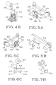
- the front broken end extractor -500-, Fig. 5A which is so called as it operates on the front part of the weaving machine, is made up of a box -502-, to one of whose sides a suction tube -503- is connected and on another side, preferably the opposite one, there is an opening -511- which extends over the entire length and continues on a portion of the adjacent sides -517-.
- Inside the box -502- there are two rollers -505- and -506- which rotate tangent to each other.
- the upper roller -505- is covered with rubber and receives the movement from the motor -507- outside the box, onto whose shaft it is connected.
- the lower roller -506- receives its movement from the upper roller -505-.
- the guiding parts -504- serve to direct the extracted thread towards the rollers.
- An opto-electronic sensor -508- or an equivalent sensitive microswitch serve for detecting the beginning and the end of the operation.
- the box -502- is inseparably joined to one arm -509- whose other end is joined to the shaft of the motor-driven reducer -510- fitted on the frame -201- of the apparatus -200-.
- 5C also consists of a box -551- which is connected to the suction tube -552- and which is provided with a longitudinal opening -553-.
- a box -551- which is connected to the suction tube -552- and which is provided with a longitudinal opening -553-.
- rollers -555- and -556- Inside the box -551- there are some rollers -555- and -556-, the first of which -555- receives the movement from the motor -557- joined on the outside of the box -551- and the second -556- receives it from the upper roller -555.
- the device -600- for selecting and feeding the auxiliary yarn -113- Fig. 6A and Fig. 6B and the means for joining the latter to the broken warp thread removed by the device -550- is located in the rear part of the frame -201- of the apparatus -200-, with this position coinciding with the rear part of the weaving machine -100-.
- the motor-driven reducer -607- is attached, to whose shaft an arm -608- has been fixed.
- a nipper -609- is attached, whose opening is carried out by means of an electromagnetic coil -610-.
- an extension -613- is included, and it is capable of picking up the broken warp thread absorbed by the extracting device.
- a flat section -611- slides, moved by a stepping motor, in the direction shown by the double arrow -621- which has a determined number of clip-knives -622-.
- Fig. 6C Each one of these clip-knives -612- is made up of a shaft -622- in which one of the cutting blades -614- of the knife is linked, and to which the moving gripper -615- of the nipper has been fixed, while the other blade -614a- of the knife and the gripper -615a- are fixed on to the flat section -611-.
- the shears and mentioned grippers are usually closed by the action of a spring -616-, and can be opened by the action of the electromagnetic coil -617-.
- Each one of these clip-knives -612- carries a thread -113- which corresponds to the different colours, materials, count and actual characteristics of the threads making up the warp which is being manufactured on the weaving machine which is the object of the repair w ork.
- the mentioned auxiliary yarns come from a mini-creel -618- carrying some coils which is also supported by the rear frame of the device. On the same frame and almost coinciding with the end of the stroke of the nipper -609- a knotter device -619- is attached, and it is driven by an electromagnet -620-.
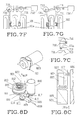
- the threading device -700- of the drop wire, Fig. 7A is made up of a hollow cylinder -701- on whose periphery there is a groove -702- in which a fine flat strip of steel -703- is housed, one of whose ends is attached to the cylinder -701-.
- This cylinder can turn around a vertical shaft -704- which is supported by a sliding part -705- which moves on some vertical guideways -706- due to the action of a motor and its conventional traction organs.
- a spring -708- is housed, which is joined by one of its ends to the inside part of the cylinder -701- and by the other end to the fixed shaft -704- with which the steel strip -703- tends to coil in the groove -702- of the periphery of the cylinder -701-.
- This steel strip -703- has its outer free end which passes between two friction cylinders -709- and -710- moved by the gears -711- and -712- and by the motor -713- and by the guideway -714- incorporated in an opto-electronic stroke sensor -715- or any other similar or equivalent means.
- Both the cylinders -709- and -710- and the motor -713-, sensor -715- and guideways -714- are supported by a part -707- which is joined to the slide -705- and which supports the cylinder -701-.
- Another element in the threading device -700- of the drop wires is the strip guide -716- Fig. 7B and 7D which is linked to the frame -201- of the apparatus -200-.
- the mentioned strip guide -716- goes between the rows of drop wires -101- almost level the the warp, and has a wide inlet -717- and a narrow outlet -717a- so as to guide the strip -703- properly.
- Another element in the threading device -700- for the drop wire is made up by parts -731- and -731a- of Figs. 7F and 7G associated to the drop wire -300- counter. These parts -731- and 731a- can turn on the supports -733- and the end of their arm has a delta shape, with its tip corresponding exactly to the vertical plane which pases through the centre of the reflection photocells -304- and -305-. Both parts -731- and -731a- can go from an inoperative position to an operative position by means of the action of the electromagnet -732-.
- Another element in the threading device -700- are the separating lifting parts -718- and -719- which Fig.
- the sliding part -723- is driven on its vertical guideways -724- by the motor -725- and traditional transmission elements such as belts and pulleys.
- the parts -718- and -719- can be moved independently on the guideway -720- and be separated or brought together as they are actioned by different motors. This parts are sufficiently long so as to be able to descend to a position below the plane of the warp.
- Another element in the threading device -700- is the guideway -726- Fig. 7D which extends from the strip guide -716- elements outlet between the drop wires up to the rear part where the warp thread has been knotted with the auxiliary yarn -113-.
- This guideway -726- consists of a rule which has a groove -735- on the side which is closest to the warp and which is sufficiently wide and deep so as to allow the passage of the steel strip -703-.
- due to the parts -727- in which it is linked it can be provided with a descending movement which allows it to place itself at the same height corresponding to the steel strip -703- when it takes its active position, and to move from the warp surface when the device is moved.
- FIG. 8A Another element in the threading device -700- is the one which serves for transferring the thread picked up by the steel strip -703- to the drawing-in device -800-.
- FIG. 8A it consists of a motor-driven reducer -728- attached to the slide -705- on whose shaft an arm -730- has been attached to the end of which there is a slant catching slot -729- and which, in its circular movement, can move the mentioned end from a position near the strip -703- tip to another position near the tip of strip -811-.
- 8A and 8B is made up of a sliding part -801- which moves on some horizontal guideways -802- which extend from the base plate -205- of the device -200- to the proximity of the harness -109-.
- This slide -801- is actioned by a motor-driven reducer -803- with its corresponding pulleys and belts or its equivalent transmission means.
- the mentioned part has a motor-driven reducer -804- attached to it, on whose shaft the ends of two plates -805- and -806- are attached, whose length is equal to the thickness of all the harnesses -109- plus the distance from the first harness to the reed -103- on the threading position plus a separation which is slightly greater than the radius of the motor -804- in the rear position.
- the external sides of the plates -805- and -806- are smooth and fine, as are their internal sides so as to allow the heddle -108a- and thread -133- to slide.
- Another element making up the device -800- for drawing the auxiliary yarn through the heddle -108- and through the space -105- of the reed is made up, the same as in the case of threading the drop wire, of a hollow cylinder -809- on whose periphery there is a groove -810- which houses a fine, flat steel strip -811-, one of whose ends is attached to the cylinder -809-.
- This cylinder -809- can turn round a vertical shaft -812- and inside the same cylinder -809- there is a spring -813- joined by one of its ends to the inside part of the cylinder -809- and by the other end to the fixed shaft -812- with which the steel strip -811- tends to coil, supported on the slot -810- of the periphery.
- This steel strip has a free external end which passes between two friction cylinders -814- and -815- (moved by gears -816- and -817- and motor -818-) and by the guiding part -819- which incorporates an opto-electronic stroke sensor -820- or a similar organ.
- Both the rollers -814- and -815- and the motor -818- and the guiding part -819- are supported by a part -821- which is attached to the end of an arm -822-.
- the other end of the mentioned arm -822- is attached to the shaft of a motor-driven reducer -823- firmly fixed to the frame -201- of the apparatus -200- and precisely in the part coinciding with the front part of the weaving machine -100-.
- a stationary support line -206- is mounted, which may be, for example, a guiding rail -206- which is arranged to extend between the aisle -119- of the rows -118- of the different weaving machines -100-.
- This support line -206- has some transportation and displacements means -207-, for example Fig. 9A, a mobile motorized carriage -207- controlled by the control system -900-, and the mentioned carriage -207- transports the frame -201-.
- the mentioned frame -201- carries at least some of the devices -300-, -400-, -500-, -600-, -700-, -800-, -900- which make up the apparatus -200-. Due to the orders from the control system -900-, it is placed on the guiding rail -102- installed in the weaving machine -100- so as to carry out all the repairs which are described in this report at a local level.
- the control system -900- which in the example described is called, at least partially, a PLC control device, may be made up of one or several elements, some fixed ones and the others mobile ones, for example supported by the actual frame -201- of the apparatus -200- so as to reduce the lengths of the electrical connections carrying the information and orders from one part of the apparatus -200- to another.
- the data transmission system may be wireless for example by radio and using coded messages for each one of the operations or operation sequences to be carried out.
- the apparatus is combined with some auxiliary means for the correct positioning of the weaving machine.
- the weaving machine For using the broken warp thread repair apparatus on weaving machines, the weaving machine must be stopped in a way other than that which is usually used. It is known that when repairs have to be carried out by hand, the loom is prepared so that it stops with the harnesses flat (when all the warp threads are horizontal) so as to facilitate the operation.
- the automatic apparatus -200- it is necessary that the position of the weaving machine, when it stops, is with the reed separated from the cloth and with the minimum sufficient for the elements in the devices -400- and -500- situated between the reed and the cloth to operate, with a semi-open shed.
- the harness to which the heddle -108a- to be drawn-in corresponds is situated in the upper part and at a prefixed height which is the same for all cases, which is obtained by setting a sensor -110- Fig. 8B (magnetic, inductive, capacitative or similar) to an end of each frame -109- and an activating organ -111- fixed to the loom -100- opposite a determined point in its stroke, or vice versa.
- the different devices in the repairing device may be operated suitably and they will have space for doing so as the harnesses -109- and the reed -103- are duly positioned.
- the drop wire -101a- falls and the machine stops on the position predetermined by the auxiliary positioning means previously mentioned.
- the stop signal is given and it is received by the control equipment (PLC) -900- of the repairing apparatus -200-, and the apparatus goes to this machine, in the event of all or part of it not being fixed to the same.
- the apparatus -200- is in relation with the memory of the control system -900- which contains all the information on the cloth and the machinery which is necessary for carrying out the repair.
- the signal received includes as information the row of drop wires where the drop wire -101a- is that has brought about the stop.
- the motor moving the drop wire sensor-counter -301- starts up to occupy the correct position so as to enter precisely in that row.
- the motor -404- turning the arm -403- starts up and places the opto-electronic reed space sensor-counter -401- and the strip-guide part -402- on the surface of the reed -103- and a sufficient distance away from the firt reed space occupied by the warp.
- the reed space counter -401- takes a few centimeters of its travel to reach that first reed space occupied by the warp where it must start counting the mentioned spaces. This effect is achieved on covering the reed surface where the sensor -401- is placed by means of a plate up to the first mentioned usable reed space, the first point where it must start counting the mentioned spaces.
- the motor -202- driving the apparatus on the rail -102- is started up, and the sensor-counter -301- penetrates into the corresponding drop wire row. This sensor starts to count from the first drop wire in the row.
- the lower counter -304- does not correspond to the upper one -305- due to the fact that it has reached the drop wire -101a- which has fallen, the displacement and counting stop.
- the counting device has positioned itself opposite the drop wire -101a- corresponding to the thread requiring repair.
- the electronic control device (PLC) together with the information the mentioned control system -900- has stored regarding the composition of the warp and its drawing in through drop wires, harness heddles and reed, as well as selvages determines the characteristics of the broken thread (colour, count, twist, material, characteristics and similar points) as well as the harness in which the heddle is in which the broken thread was drawn and also the space -105- of the reed -103- through which the same passed.
- the mentioned PLC control device will give the orders to the different devices in the repairing apparatus and auxiliary means in the weaving machine so that the following operations are carried out.
- the coil -732- makes the delta parts -731- go in between the two immediate drop wires by the fallen drop wire -101a-, separating them enough so that the ends of the lifting parts -718- and -719- can go in together.
- the motor-driven reducer -725- starts up, making the sliding part -723- come down, and consequently the parts -718- and -719- which are precisely on the vertical shaft of the sensor-counter -301- and consequently of the drop wire -101a-.
- the ascent and descent motor -725- stops and the motor -202- of the apparatus -200- starts up slowly, and likewise motors -721- and -722-, with the latter tending to displace the parts -718- and -719- in the opposite direction to the displacement of the apparatus -200-, giving it an equivalent speed.
- the lifting parts -718- and -719- and consequently the drop wire -101a- held back between them are made to stay in their original position suitable for the drop wire -101a- to be thread later.
- the sensor-counter -401- of the reed spaces continues to count them until the number reached is equivalent to that which the control unit -900- has computerized which was the one which corresponded to the broken thread.
- the device stops when the sensor-counter -401- and consequently the guide -402- which is attached to it are exactly in this space -105- corresponding to that of the broken thread.
- control unit -900- Once the control unit -900- has determined the stopping of the displacement motor -202-, it starts up the motors -721- and -722- in opposite directions, so that the lifters -718- and -719- move from the drop wire -101a- and consequently separate the immediate lateral warp threads from the drop wire and the broken thread, leaving sufficient space between the same so that the extraction and drawing-in action can be carried out more easily.
- the motor-driven reducer -510- is started up, which, by means of the arm -509- driven by its shaft, places the front broken thread extractor -500- on the upper shed.
- the exhaust fan -501- has been started up, which directs its action through the pipe -503- to the mentioned extractor -500-.
- the suction lifts up the broken thread which penetrates through the opening -511- and is directed (by the guides -504-) towards the rollers -505- and -506- which pull the loop-shaped broken thread inside the suction pipe -503-.
- the sensor -508- controls the completion of the extraction (which can also be carried out by timer).
- the extractor -500- is lifted up by the arm -509- of the motor -510- sufficiently with regard to the shed surface so as to given way to the knife -515- which is driven by the motor-driven reducer -516-.
- This knife -515- passes beneath the extractor -500- and approaching the counterblade -514- it stops and they go down together through the action of the motor -513- which is assembled on the arm -512-, until reaching the surface of the cloth -112-.
- the thread is taken in sufficiently so that it goes between the driving rollers -555- and -556-, with the thread being introduced inside the suction pipe -552- in a loop shape until the operation is considered to have been completed when its end has gone through the sensor -554-.
- the extractor -550- rises, keeping the thread inside due to reduced suction in such a way that it can be picked up and transferred to the knotter device -619-.
- the downward movement of the nipper -609- continues until the selected thead -113- is between its grippers. Then the descending movement stops and the coil -610- stops actuating, and thus the nipper closes, with the end of the thread -113- being retained by the nipper -609- at the same time as the gripper shear -612- opens, and from then on the thread can be pulled with the nipper -609- when the latter moves by means of the motor -607- and by the action of the motor -603- which moves the horizontal sliding part -602-. At the same time as the nipper -609- moves horizontally, it has two descent-ascent movements produced by the motor -607-.
- the auxiliary yarn -113- is kept threaded inside the thread guides with brake -606-. The same is then lifted up with the combined horizontal transfer movement produced by the motor -603- and the ascent and descent movement produced by the circular movement of the motor -607-.
- the thread -115- retained by the extractor -550- Fig. 6A and which is pulled by the extension -613- and the auxiliary yarn -113- caught by the nipper -609- are put in the knotter device -619, which, through the action of the electromagnet -620-, knots them.
- the cut-off ends of the yarn are sucked up by the exhaust fan -550- suction pipe.
- the drop wire -101a- threading operation whose initial part, so as to abbreviate the cycle, may coincide with the final part of the selecting and knotting operation of the device -600- which we have just described, commences with the starting up of the motors -721- and -722- in opposite directions which makes the lifting parts -718- and -719- draw together until the drop wire -101a- is held between them. Once this movement is stopped, the motor -725- is started up, which brings about the vertical displacement of the lifters -718- and -719- and consequently the lifting of the drop wire -101a- held between the mentioned parts, up to the maximum height which its stroke allows with regard to the warp stop-motion bar -106- Fig.
- the motor-driven reducer -735- starts up, which transports the threading device -700- from its raised, inoperative position to an operative position by the warp place.
- the motor-driven reducer -713- starts up and the friction cylinders -709- and -710- pull the steel strip -703- outwards, opening it out with regard to the groove in the cylinder -701- and making in penetrate through the strip guide -716-.
- This strip -703- passes from one to another until it finds the eye -116- in the drop wire -101a-.
- this drop wire -101a- has the maximum possible opening -116- due to the slanting of the walls Fig. 7C of the lifting parts -718- and -719-.
- the strip -703- pases through the opening in the drop wire -101a- and through the strip guides -716- that there may be after same.
- the mentioned strip -703- goes in the guide -726- which extends from the last row of drop wires up to the centre of the yarn guides -606- in which the auxiliary yarn -113- has been put and braked prior to being knotted with the thread -115- in the warp beam.
- the strip -703- after passing the guide -726- surpasses the thread extended between the mentioned yarn guides -606-.
- the stroke sensor -715- of the strip -703- determines that the same will move in the opposite direction, that is, in the direction it is wound on the cylinder -701-.
- the slanting slot -736- made in the end of the strip -703-, it takes and pulls the auxiliary yarn -113- knotted to the thread -115- in the warp beam, which unwinds from the corresponding coil of the feeding creel -618- and makes it pass with this return movement through the orifice -116- of the drop wire -101a-.
- This cutting action must be carried out at such a point where it free end can be absorbed by the front exhaust fan -500- suction once it has been drawn in through the heddle --108a- and the space -105- of the reed -103-.
- the end of the auxiliary yarn -113- from the coil of the creel -618- is automatically caught by the nipper -615- incorporated with the knife -612- when the thread is cut.
- the motor-driven reducer -804- corresponding to the device for drawing the auxiliary yarn in through the heddle -108a- and through the reed space -105- starts up and with a 90 degree turn, places the plates -805- and -806- within the warp plane, and precisely between the threads next to the broken thread, by the effect of separation between the warp threads which has been carried out by the parts -718- and -719- when the latter were as far as possible apart.
- the motor -803- starts up, which pulls the sliding part -801- (to which the motor -804- is attached, as well as its plates -805- and -806-) in the direction of the harnesses -109- of the weaving machine, with the plates -805- and -806- penetrating between the heddles -108-.
- These heddles -108- are, with their corresponding threads, positioned on both sides of the plates -805- and -806-, excepting the heddle -108a- which contained the broken thread, which, as it was not compelled by the thread to place itself on one side of the plates, penetrates between same with the ease given by the chamfers -807- on its front side.
- the plates -805- and -806- continue forwards between the harnesses -109-, whatever the harness which contained the heddle to be drawn in until surpassing the front line of the harnesses, stopping a short distance away from the reed -103-.
- the motor -823- fixed to the front frame of the device -200- starts moving and detains the arm -822-.
- the motor -818- starts up, which starts the friction cylinders -814- and -815- pulling steel strip -811- moving.
- the mentioned strip -811- directed by the guide -819- attached to the displacement sensor -820-, in introduced into the inlet guide -402- of the space -105- and crosses the reed -103-. After it enters the moving guide -824- between the plates -805- and -806- and goes through the eye -107- of the heddle -108a-, continuing along the guide -824- between the mentioned plates -805- and -806- until reaching the outer part of the same, also outside the harness -109- frame.
- the motor-driven reducer -728- starts up and the groove -729- located at the end of the arm -730- which is attached to its shaft picks up the auxiliary yarn -113- from the end of the steel strip -703- and places it near the steel strip -811- which, in its return movement, catches the mentioned yarn -113- by means of the groove -828- existing at its end.
- the mentioned yarn is pulled towards the internal guide of the plates -804- and -805- and threaded, being drawn in the eye -107- of the heddle -108a-.
- the motor -516- which drives the knife -515- starts up and making the knife pass beneath the extractor -500- pulls the mentioned thread very close to the counterblade -514-, its movement being detained and the motor -513- which has both knives -514- and -515- starting up, until touching the surface of the cloth together with the yarn inserted between the knives.
- This yarn iskept tense by the action of the suction of the extractor -500-.
- the motor -404- separates the reed space sensor counter -401- from the surface of the reed -103- and places it in its transfer position.
- the electronic control device -900- checks that all the devices making up the apparatus -200- (excepting the knives -514- and -515-) are on the transfer position and that the weaving machine is ready to be started up. Once this condition has been checked, the weaving machine starts up and after a few seconds, that is when the auxiliary yarn -113- has been sufficiently bound by the weft, the motor -516- starts up, which drives the knife -515- until the end of the thread which protrudes from the surface of the cloth is cut off and then the mentioned knifes are raised by the arm -512- and the motor -513- up to their transfer position, awaiting the next operation.
Landscapes
- Engineering & Computer Science (AREA)
- Textile Engineering (AREA)
- Mechanical Engineering (AREA)
- Looms (AREA)
- Auxiliary Weaving Apparatuses, Weavers' Tools, And Shuttles (AREA)
Applications Claiming Priority (2)
| Application Number | Priority Date | Filing Date | Title |
|---|---|---|---|
| GB8823734 | 1988-10-10 | ||
| GB8823734A GB2223511B (en) | 1988-10-10 | 1988-10-10 | Apparatus and method for automatically repairing broken warp threads in weaving machines or looms |
Publications (3)
| Publication Number | Publication Date |
|---|---|
| EP0364404A2 true EP0364404A2 (fr) | 1990-04-18 |
| EP0364404A3 EP0364404A3 (fr) | 1991-08-07 |
| EP0364404B1 EP0364404B1 (fr) | 1993-12-01 |
Family
ID=10644964
Family Applications (1)
| Application Number | Title | Priority Date | Filing Date |
|---|---|---|---|
| EP89810752A Expired - Lifetime EP0364404B1 (fr) | 1988-10-10 | 1989-10-04 | Appareil et méthode pour réparer automatiquement les fils de chaînes cassés dans les métiers à tisser |
Country Status (5)
| Country | Link |
|---|---|
| US (1) | US5046535A (fr) |
| EP (1) | EP0364404B1 (fr) |
| JP (1) | JP2662055B2 (fr) |
| DE (1) | DE68911104T2 (fr) |
| GB (1) | GB2223511B (fr) |
Cited By (1)
| Publication number | Priority date | Publication date | Assignee | Title |
|---|---|---|---|---|
| EP0453965A3 (en) * | 1990-04-18 | 1992-04-08 | Tsudakoma Corp. | Warp mending device |
Families Citing this family (6)
| Publication number | Priority date | Publication date | Assignee | Title |
|---|---|---|---|---|
| DE59007503D1 (de) * | 1989-11-10 | 1994-11-24 | Rueti Ag Maschf | Verfahren und Einrichtung zum Einziehen eines Kettfadens in eine Webmaschine, insbesondere in ein Webblatt. |
| JPH03161555A (ja) * | 1989-11-20 | 1991-07-11 | Toyota Autom Loom Works Ltd | 織機における経糸通し検出装置 |
| JP2731973B2 (ja) * | 1990-07-30 | 1998-03-25 | 株式会社日立製作所 | 電動機制御システム |
| BE1004740A3 (nl) * | 1991-04-09 | 1993-01-19 | Picanol Nv | Werkwijze en inrichting voor het afzonderen van een draadeinde van een gebroken kettingdraad uit de ketting bij een weefmachine. |
| JPH0525754A (ja) * | 1991-07-10 | 1993-02-02 | Tsudakoma Corp | たて糸シート揃え装置および筬管理装置 |
| CN114318695B (zh) * | 2021-12-28 | 2023-03-24 | 阿利斯教育装备科技(苏州)有限公司 | 一种高效的全自动毛织机 |
Family Cites Families (12)
| Publication number | Priority date | Publication date | Assignee | Title |
|---|---|---|---|---|
| FR708306A (fr) * | 1930-12-24 | 1931-07-22 | Perfectionnements dans les casse-chaîne mécaniques à barres dentées pour métiers à tisser | |
| FR1467134A (fr) * | 1965-12-13 | 1967-01-27 | Cotonniere De Fives | Perfectionnement aux casse-chaînes électriques de métiers à tisser |
| GB1266527A (fr) * | 1969-06-10 | 1972-03-08 | ||
| CH567127A5 (fr) * | 1973-07-24 | 1975-09-30 | Sulzer Ag | |
| GB1463543A (en) * | 1973-07-25 | 1977-02-02 | Nishiki Sangyo Kk | Apparatus for automatically stopping a weaving loom upon breakage of a warp yarn |
| JPS609952A (ja) * | 1983-06-29 | 1985-01-19 | 株式会社豊田自動織機製作所 | 織機における切断経糸処理方法 |
| JPS6081355A (ja) * | 1983-10-08 | 1985-05-09 | 株式会社豊田自動織機製作所 | 織機における経糸切断位置検出装置 |
| JPH0735625B2 (ja) * | 1985-09-17 | 1995-04-19 | 津田駒工業株式会社 | たて糸の切れ端分離方法およびその装置 |
| NL8600372A (nl) * | 1986-02-14 | 1987-09-01 | Picanol Nv | Inrichting voor het bepalen van de plaats van een kettingbreuk bij weefmachines met kettingwachterlamellen. |
| DE3764218D1 (de) * | 1986-07-08 | 1990-09-13 | Picanol Nv | Verfahren und vorrichtung zum vereinfachen der reparatur eines kettfadens in webmaschinen mit abstellamellen. |
| BE1000376A4 (nl) * | 1987-03-13 | 1988-11-16 | Picanol Nv | Werkwijze voor het ter hoogte van de kettingwachter afzonderen van een gebroken kettingdraad uit de ketting bij een weefmachine, alsook inrichting die deze werkwijze toepast. |
| BE1000899A4 (nl) * | 1987-09-02 | 1989-05-09 | Picanol Nv | Werkwijze voor het kontroleren van kettingbreuken bij weefmachines, en inrichting die deze werkwijze toepast. |
-
1988
- 1988-10-10 GB GB8823734A patent/GB2223511B/en not_active Expired - Fee Related
-
1989
- 1989-10-04 EP EP89810752A patent/EP0364404B1/fr not_active Expired - Lifetime
- 1989-10-04 DE DE89810752T patent/DE68911104T2/de not_active Expired - Fee Related
- 1989-10-05 US US07/417,312 patent/US5046535A/en not_active Expired - Lifetime
- 1989-10-11 JP JP1270576A patent/JP2662055B2/ja not_active Expired - Lifetime
Cited By (2)
| Publication number | Priority date | Publication date | Assignee | Title |
|---|---|---|---|---|
| EP0453965A3 (en) * | 1990-04-18 | 1992-04-08 | Tsudakoma Corp. | Warp mending device |
| US5141030A (en) * | 1990-04-18 | 1992-08-25 | Tsudakoma Corp. | Warp mending device for feeding a mending yarn to drop wires and a heddle |
Also Published As
| Publication number | Publication date |
|---|---|
| DE68911104D1 (de) | 1994-01-13 |
| DE68911104T2 (de) | 1994-05-11 |
| JP2662055B2 (ja) | 1997-10-08 |
| US5046535A (en) | 1991-09-10 |
| EP0364404A3 (fr) | 1991-08-07 |
| EP0364404B1 (fr) | 1993-12-01 |
| GB8823734D0 (en) | 1988-11-16 |
| GB2223511B (en) | 1992-08-26 |
| GB2223511A (en) | 1990-04-11 |
| JPH02216244A (ja) | 1990-08-29 |
Similar Documents
| Publication | Publication Date | Title |
|---|---|---|
| CN105019076B (zh) | 带引纱的环锭细纱断头自动智能接头方法与装置 | |
| US5046535A (en) | Automatic repair of broken warp threads in weaving machines | |
| CN115676513A (zh) | 用于抽出并卷绕丝线的设备 | |
| US7165740B2 (en) | Travelling service device for open-end spinning units of open-end spinning machines | |
| US5050643A (en) | On loom system for mending broken warp yarn | |
| CZ283051B6 (cs) | Zařízení k navádění osnovních nití | |
| EP0318047B1 (fr) | Procédé et dispositif pour couper un fil de réparation | |
| JPS6269851A (ja) | たて糸の切れ端分離方法およびその装置 | |
| EP0449279B1 (fr) | Méthode pour localiser l'espacement entre des dents correspondant à un fil de chaîne cassé, et dispositif de localisation et de rentrage | |
| EP0449277B1 (fr) | Procédé pour restaurer un fil de chaîne cassé après sa réparation | |
| EP0960964A1 (fr) | Procédé et appareil pour le raccordement automatique d'un fil au stade de formation dans un métier à filer | |
| KR930010101B1 (ko) | 경사보수 장치 | |
| US3458984A (en) | Bobbin-handling mechanism | |
| US4324094A (en) | Semiautomatic device for doffing spools from a spindle bench | |
| JP2796875B2 (ja) | たて糸の筬通し方法 | |
| JP2000037582A (ja) | ミシンにおける糸切断装置およびこの糸切断装置の使用方法 | |
| JP2838227B2 (ja) | 織機の糸通し用位置決め装置 | |
| JP2696717B2 (ja) | 切断たて糸の筬羽位置検出装置 | |
| JP2722233B2 (ja) | たて糸自動補修方法 | |
| JP2805530B2 (ja) | 切断たて糸の筬羽位置検出方法 | |
| US3220442A (en) | Loom for the automatic weaving of broad fabrics with more than one shuttle | |
| JP2643139B2 (ja) | 無杼織機における緯糸処理方法 | |
| JP2777741B2 (ja) | 筬羽位置検出方法 | |
| EP0321019A1 (fr) | Procédé et dispositif de bobinage du fil sur une bobine qui manque d'une longeur de fil nécessaire à la reconnexion automatique dans un métier à filer à anneau | |
| JPH0441748A (ja) | たて糸補修装置 |
Legal Events
| Date | Code | Title | Description |
|---|---|---|---|
| PUAI | Public reference made under article 153(3) epc to a published international application that has entered the european phase |
Free format text: ORIGINAL CODE: 0009012 |
|
| AK | Designated contracting states |
Kind code of ref document: A2 Designated state(s): BE CH DE FR IT LI NL |
|
| 17P | Request for examination filed |
Effective date: 19900518 |
|
| PUAL | Search report despatched |
Free format text: ORIGINAL CODE: 0009013 |
|
| AK | Designated contracting states |
Kind code of ref document: A3 Designated state(s): BE CH DE FR IT LI NL |
|
| 17Q | First examination report despatched |
Effective date: 19920324 |
|
| GRAA | (expected) grant |
Free format text: ORIGINAL CODE: 0009210 |
|
| AK | Designated contracting states |
Kind code of ref document: B1 Designated state(s): BE CH DE FR IT LI NL |
|
| REF | Corresponds to: |
Ref document number: 68911104 Country of ref document: DE Date of ref document: 19940113 |
|
| ITF | It: translation for a ep patent filed | ||
| ET | Fr: translation filed | ||
| PLBE | No opposition filed within time limit |
Free format text: ORIGINAL CODE: 0009261 |
|
| STAA | Information on the status of an ep patent application or granted ep patent |
Free format text: STATUS: NO OPPOSITION FILED WITHIN TIME LIMIT |
|
| 26N | No opposition filed | ||
| PGFP | Annual fee paid to national office [announced via postgrant information from national office to epo] |
Ref country code: NL Payment date: 20020925 Year of fee payment: 14 Ref country code: DE Payment date: 20020925 Year of fee payment: 14 |
|
| PGFP | Annual fee paid to national office [announced via postgrant information from national office to epo] |
Ref country code: FR Payment date: 20020926 Year of fee payment: 14 Ref country code: CH Payment date: 20020926 Year of fee payment: 14 |
|
| PGFP | Annual fee paid to national office [announced via postgrant information from national office to epo] |
Ref country code: BE Payment date: 20021016 Year of fee payment: 14 |
|
| PG25 | Lapsed in a contracting state [announced via postgrant information from national office to epo] |
Ref country code: LI Free format text: LAPSE BECAUSE OF NON-PAYMENT OF DUE FEES Effective date: 20031031 Ref country code: CH Free format text: LAPSE BECAUSE OF NON-PAYMENT OF DUE FEES Effective date: 20031031 Ref country code: BE Free format text: LAPSE BECAUSE OF NON-PAYMENT OF DUE FEES Effective date: 20031031 |
|
| BERE | Be: lapsed |
Owner name: S.A. *TEXIPAT Effective date: 20031031 |
|
| PG25 | Lapsed in a contracting state [announced via postgrant information from national office to epo] |
Ref country code: NL Free format text: LAPSE BECAUSE OF NON-PAYMENT OF DUE FEES Effective date: 20040501 Ref country code: DE Free format text: LAPSE BECAUSE OF NON-PAYMENT OF DUE FEES Effective date: 20040501 |
|
| REG | Reference to a national code |
Ref country code: CH Ref legal event code: PL |
|
| PG25 | Lapsed in a contracting state [announced via postgrant information from national office to epo] |
Ref country code: FR Free format text: LAPSE BECAUSE OF NON-PAYMENT OF DUE FEES Effective date: 20040630 |
|
| NLV4 | Nl: lapsed or anulled due to non-payment of the annual fee |
Effective date: 20040501 |
|
| REG | Reference to a national code |
Ref country code: FR Ref legal event code: ST |
|
| PG25 | Lapsed in a contracting state [announced via postgrant information from national office to epo] |
Ref country code: IT Free format text: LAPSE BECAUSE OF NON-PAYMENT OF DUE FEES;WARNING: LAPSES OF ITALIAN PATENTS WITH EFFECTIVE DATE BEFORE 2007 MAY HAVE OCCURRED AT ANY TIME BEFORE 2007. THE CORRECT EFFECTIVE DATE MAY BE DIFFERENT FROM THE ONE RECORDED. Effective date: 20051004 |