EP0365028B1 - Überlagerungsempfänger für kohärente optische Übertragung - Google Patents
Überlagerungsempfänger für kohärente optische Übertragung Download PDFInfo
- Publication number
- EP0365028B1 EP0365028B1 EP89119515A EP89119515A EP0365028B1 EP 0365028 B1 EP0365028 B1 EP 0365028B1 EP 89119515 A EP89119515 A EP 89119515A EP 89119515 A EP89119515 A EP 89119515A EP 0365028 B1 EP0365028 B1 EP 0365028B1
- Authority
- EP
- European Patent Office
- Prior art keywords
- signal
- polarization
- output
- light
- signals
- Prior art date
- Legal status (The legal status is an assumption and is not a legal conclusion. Google has not performed a legal analysis and makes no representation as to the accuracy of the status listed.)
- Expired - Lifetime
Links
Images


Classifications
-
- H—ELECTRICITY
- H04—ELECTRIC COMMUNICATION TECHNIQUE
- H04B—TRANSMISSION
- H04B10/00—Transmission systems employing electromagnetic waves other than radio-waves, e.g. infrared, visible or ultraviolet light, or employing corpuscular radiation, e.g. quantum communication
- H04B10/60—Receivers
- H04B10/61—Coherent receivers
- H04B10/614—Coherent receivers comprising one or more polarization beam splitters, e.g. polarization multiplexed [PolMux] X-PSK coherent receivers, polarization diversity heterodyne coherent receivers
-
- H—ELECTRICITY
- H04—ELECTRIC COMMUNICATION TECHNIQUE
- H04B—TRANSMISSION
- H04B10/00—Transmission systems employing electromagnetic waves other than radio-waves, e.g. infrared, visible or ultraviolet light, or employing corpuscular radiation, e.g. quantum communication
- H04B10/60—Receivers
- H04B10/61—Coherent receivers
- H04B10/64—Heterodyne, i.e. coherent receivers where, after the opto-electronic conversion, an electrical signal at an intermediate frequency [IF] is obtained
Definitions
- the present invention relates to an optical transmitting and receiving apparatus of a heterodyne detecting system applicable to a coherent optical transmission which is expected to be applied to a long-distance large-capacity communication, and more particularly to an improvement of a circuit portion for positively controlling the polarization state of a signal light.
- a heterodyne detecting system In coherent optical communication, a heterodyne detecting system is used to detect a signal light received through a light transmission path, and to also detect a local oscillation light.
- the polarization state of a signal varies during its period of transmission along an optical fiber.
- a method is required for positively controlling the polarization states of a signal light and a local oscillation light.
- Figure 1 shows a circuit structure of a prior art heterodyne detecting receiving apparatus used to achieve this positive control.
- the signal light transmitted through an optical fiber is inputted to mixing circuit 2 through polarization apparatus 1 and is then mixed with local oscillation light outputted from optical local oscillating circuit 3.
- the local oscillating light is assumed to be in a polarized state in which the principal axis angle is slanted, for example, by 45 degrees and the elliptic ratio is 1.
- One output signal from mixing circuit 2 is subjected to a heterodyne detection by optical receiver 4 and is converted to an intermediate frequency signal. This intermediate frequency signal is demodulated by demodulator 5 and outputted therefrom.
- the other output signal from mixing circuit 2 is used to monitor the polarization state of the signal light.
- the optical signal for monitoring is first divided into two portions by half mirror 6 and the transparent light is separated by polarization splitter 7 into two polarization components which intersect at right angles.
- the optical signal is thereafter converted into an electrical signal by optical receivers 8 and 9.
- the light reflected from half mirror 6 is subjected to a conversion of its polarization state by ⁇ /4 plate 10 (for example, a linearly polarized light is converted to a circularly polarized light or a circularly polarized light is converted into a linearly polarized light) and subsequently the reflected light is separated into two orthogonal polarization components by polarization splitter 11, whose axis is rotated 45 degrees from that of polarization splitter 7 and is thereafter converted into an electrical signal by optical receivers 12 and 13.
- the output signals from optical receivers 8 and 9 are inputted to differential amplifier 14 and the output signals from optical receivers 12 and 13 are inputted to the other differential amplifier 15.
- Differential amplifier signals A and B obtained from differential amplifiers 14 and 15 are used as monitor signals by polarization operation apparatus 1 to control the polarization state of the signal light.
- the principal axis angle of the polarization state of the signal light is controlled by making signal A equal to 0 and the elliptic ratio is controlled by making signal B equal to 0.
- a part of the signal light is divided into two portions by half mirror 6 and polarization splitters 7 and 11, and the polarization state of the signal light is monitored by four optical receivers 8, 9, 12 and 13, thus controlling the polarization state of the signal light.
- the structure of the optical system becomes complicated as half mirror 6, ⁇ /4 plate 10, the two polarization splitters 7 and 11, and the four optical receivers 8, 9, 12 and 13 must be used for merely monitoring the polarization state of signal light, even when optical receivers are required, resulting in the problem that the apparatus must be large. A part of the signal light is divided and used only for monitoring. Thus, the receiving sensitivity is deteriorated by an amount corresponding to the use of such a monitoring system. Further, there is a problem that the prior art apparatus cannot form a DBOR (Dual Balanced Optical Signal Receiver, refer to JP-A-1195153 (Japanese Patent Kokai No.
- JP-A-63238877 Japanese Patent Kokai No. 63-1124
- US Application No. 064058/87 EP-A-0 251 062
- EPC Application No. 87108787 EP-A-0 251 062
- CA-A-1290019 Canadian Application No. 539613/87) which makes it possible to perform a high-sensitivity receiving operation by using the signal component effectively suppressing the noise component.
- EP-A-0 245 026 discloses an optical heterodyne mixer providing image-frequency rejection and comprising a mixing optical device, a polarising splitter, respective photodetectors and a 90° image-frequency coupler.
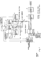
- a signal light transmitted through a light transmission path is provided to mixing circuit 21 through polarization operating apparatus 20 and a local oscillation light from optical local oscillation circuit 22 is inputted to mixing circuit 21 in which a signal light is mixed with a local oscillation light.
- the polarization state of the local oscillation light is made to have its principle axis angle slanted by, for example, 45 degrees.
- the mixed light is separated by polarization splitter 23 into two orthogonal polarization components to each other.
- the components are subjected to respective heterodyne detections in optical receivers 24 and 25 to provide an intermediate frequency signal.
- the structure explained up to this point comprises an optical system.
- the polarization state of the signal light designates circular polarization light
- the polarization state of the signal light is made to show 45-degree or 135-degree linear polarization.
- the polarization state of the signal light is made to represent circular polarization light.
- the amplified beat components are obtained from ports P4 of 90-degree hybrid coupler 26 and the image components are outputted from port P3 to cancel each other out.
- the image component can be deleted from the intermediate frequency signal outputted from port P4 by driving polarization operating apparatus 20 by polarization control circuit 29 so that signal a is made 0 as described above.
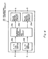
- Figure 7 shows a block diagram of the second embodiment of the present invention.
- This embodiment is formed of a DBOR (Dual Balanced Optical Reciver). Namely, another pair comprising polarization splitter 31 and optical receivers 32 and 33, having a structure similar to the aforementioned polarization splitter 23 and optical receivers 24 and 25, is provided to port P4 of mixing circuit 21 in the first embodiment. The output from optical receivers 24 and 32 are applied to subtractor 35.
- DBOR Double Balanced Optical Reciver
- the signal light is mixed with the local oscillation light in mixing circuit 21, and optical signals having a phase difference of 180 degrees are outputted from ports P3 and P4.
- These light signals are divided into equal parts by polarization splitters 23 and 31 and then subjected to heterodyne detection by light receivers 24, 25, 32 and 33.
- the intermediate frequency signal obtained by optical receivers 24 and 32 are applied to subtractor 34 and the intermediate signals obtained by optical receivers 25 and 33 are applied to subtractor 35.
- beat components having a 180-degree phase difference are inputted to optical receivers 24 and 32 and similarly beat components having a 180-degree phase difference are inputted to optical receivers 25 and 33.
- the beat components are added to be amplified and noise intensity components of the local oscillation light cancel each other in subtractors 34 and 35.
- the intermediate frequency signal in which the noise intensity component is suppressed is inputted to 90-degree hybrid coupler 26 and differential amplifier 28. Thereafter, the same process as in the first embodiment is continued.
- the present embodiment effectively utilizes two output lights from mixing circuit 21, thereby suppressing the excess intensity noise of the local oscillation light and greatly increasing the receiving sensitivity.
- the above embodiments describe the case where either the signal light or the local oscillation light is made to be in 45-degree (or 135-degree) linear polarization and the other is made to be in circular polarization. It is not always necessary to use the above arrangement. Namely, it is a required condition that both the signal light and local oscillation light be in a polarization state having their principal axes at 45 degrees, and that the phase difference between them be 90 degrees. Any polarization state satisfying the above condition may be used.
- the signal light may have elliptic polarization with 110-degree phase difference between the X components and Y components of the signal light
- the local oscillation light may have elliptic polarization with a phase difference of 20 degrees between the X and Y components of the local oscillation light.
- the circuit for inverting the signals from the power monitor 42 and the circuit for outputting the signal b by adding the output of the inverting circuit to the output from the power monitor 43 may be employed.
- polarization operating apparatus 20 instead of the structure shown in Figure 5, a wave guide device comprising an electrical optical crystal such as lithium niobate may be employed to perform a phase modulation by applying an appropriate voltage to the electrodes provided on the wave guide device, thereby enabling the polarization state of the signal light to be changed.
- a wave guide device comprising an electrical optical crystal such as lithium niobate may be employed to perform a phase modulation by applying an appropriate voltage to the electrodes provided on the wave guide device, thereby enabling the polarization state of the signal light to be changed.
- At least two optical receivers may be sufficient and thus, the structure of the optical system may be simplified and the apparatus as a whole may be miniaturized.
- the signal light is not divided merely for monitoring its polarization state and the polarization state may be monitored in the electrical signal stage. Therefore, a much higher sensitivity can be achieved upon receiving the signal light than in the prior art.
- the present invention may be easily formed using a DBOR, even higher sensitivity reception is possible.
- the image component may be deleted from the other output signal.
Landscapes
- Physics & Mathematics (AREA)
- Electromagnetism (AREA)
- Engineering & Computer Science (AREA)
- Computer Networks & Wireless Communication (AREA)
- Signal Processing (AREA)
- Optical Communication System (AREA)
Claims (27)
- Überlagerungsempfangsvorrichtung für kohärente optische Kommunikation, miteiner optischen, lokalen Oszillatorschaltung (22) zur Erzeugung eines lokalen Oszillationslichts;einer Polarisationsbetätigungsvorrichtung (20) zum Variieren des Polarisationszustands eines Signallichtes, welches durch einen Lichtübertragungsweg übertragen wird;einer Mischschaltung (21) zur Mischung eines Signallichtes, dessen Polarisationszustand durch die Polarisationsbetätigungsvorrichtung (20) korrigiert wird, mit einem lokalen Oszillationslicht, welches von der optischen, lokalen Oszillatorschaltung (22) ausgegeben wird;einem Polarisations-Strahlteiler (23), zum Trennen eines Ausgangslichtes der Mischschaltung (21) in zwei Arten von Polarisationskomponenten;optischen Empfängern (24, 25) zur Erfassung von Signalen für jede Polarisationskomponente, die von dem Polarisations-Strahlteiler (23) erhalten wird, um ein Zwischenfrequenzsignal zur Verfügung zu stellen;einer Vorrichtung (27) zum Kombinieren zweier Zwischenfrequenzsignale, die von den optischen Empfängern (24, 25) ausgegeben werden;einem Demodulator (27) zum Demodulieren eines ersten Ausgangssignales, welches von der Signalkombinationsvorrichtung (26) ausgegeben wird; undeiner Polarisationssteuerschaltung (29) zum Steuern des Polarisationszustandes des Ausgangssignals, durch Treiben der Polarisationsbetätigungsvorrichtung (20) auf der Grundlage zweiter und dritter Ausgangssignale (b, a), die von den optischen Empfängern (24, 25) bzw. der Signalkombinationsvorrichtung (27) abgeleitet werden;dadurch gekennzeichnet, daß die Signalkombinationsvorrichtung (26) einen 90°-Hybridkoppler (26) zum Kombinieren der Zwischenfrequenzsignale aufweist, die von den optischen Empfängern (24, 25) ausgegeben werden, zur Erzeugung, an einem Ausgangsport (P3), des dritten Ausgangssignals (a) und, an einem zweiten Ausgangsport (P4), eines Zwischenfrequenzsignals zur Ausgabe an den Demodulator (27) als das erste Ausgangssignal.
- Überlagerungsempfangsvorrichtung nach Anspruch 1, bei welcher sowohl beim Signallicht als auch beim lokalen Oszillationslicht die Hauptachsenwinkel um 45° geneigt angeordnet sind, und die Phasendifferenz zwischen diesen beiden 90° beträgt.
- Überlagerungsempfangsvorrichtung nach Anspruch 1 oder 2, bei welcher die optische, lokale Oszillatorschaltung (22) ein Halbleiterlaser ist.
- Überlagerungsempfangsvorrichtung nach Anspruch 1, 2 oder 3, bei welcher die Polarisationsbetätigungsvorrichtung (20) eine λ/4-Platte (20a) und eine λ/2-Platte (20b) aufweist, die in Reihe auf dem optischen Weg des Signallichts angeordnet sind, sowie einen Impulsmotor (20c, 20d) zum Drehen und Antreiben der beiden Platten.
- Überlagerungsempfangsvorrichtung nach einem der voranstehenden Ansprüche, bei welcher der Polarisations-Strahlteiler (23) das Ausgangslicht der Mischschaltung in zwei orthogonale Polarisationskomponenten aufteilt.
- Überlagerungsempfangsvorrichtung nach einem der voranstehenden Ansprüche, bei welcher der optische Empfänger (26) eine Fotodiode zur Durchführung einer Überlagerungsdemodulation eines Signals entsprechend jeweiligen Polarisationskomponenten aufweist, die durch die Polarisation erhalten werden, und zur Bereitstellung von Zwischenfrequenzsignalen, deren Phasen sich um 90° unterscheiden.
- Überlagerungsempfangsvorrichtung nach einem der voranstehenden Ansprüche, bei welcher der 90°-Hybridkoppler (26) erste und zweite Eingangsports (P1, P2) zusätzlich zu den ersten und zweiten Ausgangsports (P3, P4) aufweist, wobei die Eingangs- und Ausgangsports (P1, P2, P3, P4) dazu dienen, die Phase des in den ersten Eingangsport (P1) eingegebenen Signals um 90° zu verzögern, das verzögerte Signal dem Signal hinzuzufügen, welches von dem zweiten Ausgangsport (P4) empfangen wird, die Phase des von dem zweiten Eingangsport (P2) empfangenen Signals um 90° zu verzögern, und das verzögerte Signal an das Signal anzulegen, welches von dem ersten Eingangsport (P1) empfangen wird, und es hierdurch durch den ersten Ausgangsport (P3) auszugeben.
- Überlagerungsempfangsvorrichtung nach Anspruch 7, bei welcher der 90°-Hybridkoppler (26) so ausgebildet ist, daß er die Zwischenfrequenzsignale, die von den optischen Empfängern ausgegeben und um 90° phasenverschoben sind, und die Zwischenfrequenzsignale mit gleicher Phase addiert, und sie hierdurch von dem zweiten Ausgangsport (P4) ausgibt, damit sie an den Demodulator (27) übertragen werden, und weiterhin als Überwachung die Zwischenfrequenzsignale ausgibt, die mit entgegengesetzter Phase versehen und miteinander addiert werden, aus dem ersten Ausgangsport (P3).
- Überlagerungsempfangsvorrichtung nach Anspruch 8, bei welcher die als Überwachung von dem ersten Ausgangsport (P3) des 90°-Hybridkopplers (26) ausgegebenen Signale zu Null oder zu einem Minimalwert gemacht werden, und die Bildkomponente von dem Signal entfernt wird, welches von dem zweiten Ausgangsport (P4) des 90°-Hybridkopplers (26) ausgegeben wird.
- Überlagerungsempfangsvorrichtung nach einem der voranstehenden Ansprüche, bei welcher ein Differenzverstärker (28) zum Empfang der Ausgangssignale von den beiden optischen Empfängern vorgesehen ist, das von dem Differenzverstärker ausgegebene Signal zu einem Signal zur Überwachung des Hauptachsenwinkels des Signallichtes gemacht wird, das von dem ersten Ausgangsport (P3) des 90°-Hybridkopplers (26) ausgegebene Signal zu einem Signal zur Überwachung des Ellipsenverhältnisses des Signallichts gemacht wird, und die Polarisations- und Steuerschaltung (29) so ausgebildet ist, daß sie das Signal (b) für die Hauptachsenwinkelüberwachung und das Signal (a) zur Überwachung des Ellipsenverhältnisses empfängt.
- Überlagerungsempfangsvorrichtung nach Anspruch 10, bei welcher die Polarisationssteuerschaltung (29) so ausgebildet ist, daß sie die Polarisationsbetätigungsvorrichtung (20) so treibt, daß beide Signale (b, a) zur Überwachung des Hauptachsenwinkels und Signale zur Überwachung des Ellipsenverhältnisses zu Null oder einem Minimalwert gemacht werden.
- Überlagerungsempfangsvorrichtung nach Anspruch 11, bei welcher die Polarisationssteuerschaltung (29) jeweilige A/D-Wandler (29b, 29a) zur Durchführung einer A/D-Wandlung von Signalen zur Überwachung des Hauptachsenwinkels und des Signales zur Überwachung des Ellipsenverhältnisses aufweist, jeweilige Impulsmotortreiberschaltungen (29e, 29d) zum Treiben der Impulsmotoren (20d, 20c) für die Polarisationsbetätigungsvorrichtung (20), und eine Numerikwertbetätigungsschaltung (29c) zum Steuern der Impulsmotortreiberschaltung (29e, 29d), so daß die Ausgangssignale der A/D-Wandler (29b, 29a) zu Null oder einem Minimum gemacht werden.
- Überlagerungsempfangsvorrichtung nach Anspruch 12, bei welcher die Numerikwertbetätigungsschaltung (29c) die numerischen Daten entsprechend einem Bergsteig-Algorithmus verarbeitet.
- Überlagerungsempfangsvorrichtung nach Anspruch 10, bei welcher das Ausgangssignal von dem ersten Ausgangsport (P3) von dem 90°-Hybridkoppler (26) und die Ausgangssignale von dem optischen Empfänger (24, 25) an die Polarisationssteuerschaltung (29) und den Differenzverstärker (28) über jeweilige Leistungsüberwachungsvorrichtungen (41, 42, 43) angelegt werden, um die Leistung zu erfassen.
- Überlagerungsempfangsvorrichtung zur Verwendung bei einer kohärenten optischen Kommunikation, mit: einer optischen, lokalen Oszillatorschaltung (22) zur Erzeugung einer Schwingung eines lokalen Oszillatorlichtes,einer Polarisationsbetätigungsvorrichtung (20) zum Variieren des Polarisationszustandes des Signals, welches über einen optischen Übertragungsweg übertragen wird,einer Mischschaltung (21) zum Mischen des Signallichtes, dessen Polarisationszustand durch die Polarisationsbetätigungsschaltung (20) korrigiert wird, mit dem lokalen Oszillatorlicht, welches von der Schaltung (22) für das lokale Oszillatorlicht ausgegeben wird, und zum Unterteilen der gemischten Lichtsignale in zwei Lichtsignale, welche eine Phasendifferenz von 180° aufweisen, und von ersten und zweiten Ausgangsports (P3, P4) der Mischschaltung (21) ausgegeben werden sollen,einem ersten Polarisations-Strahlteiler (23) zum Aufteilen des von dem ersten Ausgangsport (P3) der Mischschaltung ausgegebenen Lichtes in zwei orthogonale Komponenten,ersten und zweiten optischen Empfängern (23, 25) zur Durchführung einer Überlagerungsdemodulation bei Signalen mit jeweiligen Polarisationskomponenten, die von dem ersten Polarisastions-Strahlteiler (23) erhalten werden, und zur Ausgabe eines Zwischenfrequenzsignals,einem zweiten Polarisations-Strahlteiler (31) zur Unterteilung des von dem zweiten Ausgangsport (P4) der Mischschaltung (21) ausgegebenen Lichtes in zwei orthogonale Polarisationskomponenten,dritten und vierten optischen Empfängern (32, 33) zur Durchführung einer Überlagerungs-Demodulation der Signale der selektiven Polarisationskomponente, die von dem zweiten Polarisations-Strahlteiler (31) erhalten werden, und zur Ausgabe eines Zwischenfrequenzsignals,einer ersten Subtrahiervorrichtung (34) zum Subtrahieren des Ausgangssignals des ersten optischen Empfängers (24) von dem Ausgangssignal des dritten optischen Empfängers (32),einer zweiten Subtrahiervorrichtung (35) zum Subtrahieren des Ausgangssignals des zweiten Lichtempfängers (25) von dem Ausgangssignal des vierten Lichtempfängers (33),einer Vorrichtung (26) zum Kombinieren zweier Zwischenfrequenzsignale, die von der ersten bzw. Zweiten Subtrahiervorrichtung (34, 35) ausgegeben werden,einem Demodulator (27) zum Demodulieren eines ersten Ausgangssignals, welches von der Signalkombinationsvorrichtung (26) ausgegeben wird, undeiner Polarisationssteuerschaltung (29) zum Treiben der Polarisationsbetätigungsvorrichtung (20) auf der Grundlage zweiter und dritter Ausgangssignale (b, a), die jeweils von der ersten und zweiten Subtrahiervorrichtung (34, 35) bzw. der Kombinationsvorrichtung (26) abgeleitet werden, zum Steuern des Polarisationszustandes des Signallichts, um hierdurch einen kompensierten optischen Doppelempfänger auszubilden,dadurch gekennzeichnet, daß die Signalkombinationsvorrichtung (26) einen 90°-Hybridkoppler (26) zum Kombinieren der Zwischenfrequenzsignale aufweist, die von den ersten und zweiten Subtrahiervorrichtungen (34, 35) ausgegeben werden, um an einem Ausgangsport (P3) das dritte Ausgangssignal (a) zu erzeugen, und um an einem zweiten Ausgangsport (P4) ein Zwischenfrequenzsignal zur Ausgabe an den Demodulator (27) als das erste Ausgangssignal zu erzeugen.
- Überlagerungsempfangsvorrichtung nach Anspruch 15, bei welcher sowohl das Signallicht als auch das lokale Oszillatorlicht Polarisationszustände aufweisen, bei welchen die Hauptachsen um 45° geneigt sind, und die Phasendifferenz 90° beträgt.
- Überlagerungsempfangsvorrichtung nach Anspruch 15 oder 16, bei welcher die optische, lokale Oszillatorschaltung (22) einen Halbleiterlaser aufweist.
- Überlagerungsempfänger nach Anspruch 15, 16 oder 17, bei welchem die Polarisationsbetätigungsvorrichtung (20) eine λ/4-Platte (20a) und eine λ/1-Platte (20b) aufweist, die in Reihe entlang dem Weg des Signallichtes angeordnet sind, sowie einen Impulsmotor (20c, 20d) zum Drehen sowohl der λ/4- als auch der λ/2-Platte (20a, 20b).
- Überlagerungsempfangsvorrichtung nach einem der Ansprüche 15 bis 18, bei welcher die ersten bis vierten optischen Empfänger (24, 25, 32, 33) Fotodioden aufweisen, und mit Signalen der jeweiligen Lichtpolarisationskomponenten, die von den ersten und zweiten Polarisations-Strahlteilern (23, 31) erhalten werden, eine Überlagerungs-Demodulation durchgeführt wird, wodurch Zwischenfrequenzsignale zur Verfügung gestellt werden, deren Phasen gegeneinander um 90° verschoben sind.
- Überlagerungsempfangsvorrichtung nach einem der Ansprüche 15 bis 19, bei welcher der 90°-Hybridkoppler (26) erste und zweite Eingangsports (P1, P2) zusätzlich zu den ersten und zweiten Ausgangsports (P3, P4) aufweist, und die Phase des in den ersten Eingangsport (P1) eingegebenen Signals verzögert, wobei das verzögerte Signal den Signalen hinzugefügt wird, welche in den zweiten Eingangsport (P2) eingegeben werden, und hierdurch von dem zweiten Ausgangsport (P4) ausgegeben werden, die Phase des in den zweiten Eingangsport (P2) eingegebenen Signals um 90° verzögert wird, und das verzögerte Signal dem Signal hinzugefügt wird, welches in den ersten Eingangsport (P1) eingegeben wird, um von dem ersten Ausgangsport (P3) ausgegeben zu werden.
- Überlagerungsempfangsvorrichtung nach Anspruch 20, bei welcher der 90°-Hybridkoppler (26) so ausgebildet ist, daß er die Zwischenfrequenzsignale addiert, die von den Subtrahiervorrichtungen (34, 35) ausgegeben werden, wobei diese Signale eine Phasendifferenz von 90° aufweisen, und so geändert werden, daß sie dieselbe Phase aufweisen, wodurch ein addiertes Signal zur Verfügung gestellt wird, welches von dem zweiten Ausgansport (P4) ausgegeben und an den Demodulator (27) übertragen wird, und die Zwischenfrequenzsignale, welche gegeneinander um 90° phasenverschoben sind, so ausgebildet werden, daß sie ein Signal der entgegengesetzten Phase zur Verfügung stellen, und zueinanderaddiert werden, um hierdurch von dem ersten Ausgangsport (P3) als ein Überwachungssignal ausgegeben zu werden.
- Überlagerungsempfänger nach Anspruch 21, bei welchem das Signal, welches von dem ersten Ausgangsport (P3) des 90°-Hybridkopplers (26) als ein Überwachungssignal ausgegeben wird, zu Null oder einem Minimum gemacht wird, wodurch die Bildkomponente aus den Signalen entfernt wird, die von dem zweiten Ausgangsport (P4) ausgegeben werden.
- Überlagerungsempfänger nach Anspruch 20, bei welchem ein Differenzverstärker (28) vorgesehen ist, um die Ausgangssignale von den ersten und zweiten Subtrahiervorrichtungen (34, 35) zu empfangen, das von dem Differenzverstärker (28) ausgegebene Signal zum Signal zur Überwachung des Hauptachsenwinkels des Signallichts gemacht wird, und das von dem ersten Ausgangsport (P3) des 90°-Hybridkopplers (26) ausgegebene Signal zu einem Signal zur Überwachung des Ellipsenverhältnisses des Signallichts gemacht wird, wobei die Polarisationssteuerschaltung (29) so ausgebildet ist, daß sie Signale (b) zur Überwachung eines Hauptwinkels und Signale (a) zur Überwachung des Ellipsenverhältnisses empfängt.
- Überlagerungsempfänger nach Anspruch 23, bei welchem die Polarisationssteuerschaltung (29) so ausgebildet ist, daß sie die Polarisationsbetätigungsvorrichtung (20) so treibt, daß sowohl die Signale (b) zur Überwachung des Hauptachsenwinkels als auch die Signale (a) zur Überwachung des Ellipsenverhältnisses zu Null oder einem Maximum gemacht werden.
- Überlagerungsempfänger nach Anspruch 24, bei welchem die Polarisationssteuerschaltung (29) jeweilige A/D-Wandler (29b, 29a) zur Durchführung einer A/D-Wandlung des Hauptwinkelüberwachungssignals und des Ellipsenverhältnis-Überwachungssignals aufweist, jeweilige Impulsmotortreiberschaltungen (29e, 29d) zum Treiben der Impulsmotoren (20d, 20c) der Polarisationsbetätigungsvorrichtung (20), und eine Numerikverarbeitungsschaltung zum Steuern der Impulsmotortreiberschaltung (29c), so daß sämtliche Ausgangssignale des A/D-Wandlers (29b, 29a) zu Null oder einem Minimum gemacht werden.
- Überlagerungsempfänger nach Anspruch 25, bei welchem die Numerikbearbeitungsschaltung (29c) einem Numerikvorgang unter Verwendung eines Bergsteigverfahrens unterworfen wird.
- Überlagerungsempfänger nach Anspruch 23, bei welchem das Ausgangssignal von dem ersten Ausgangsport (P3) des 90°-Hybridkopplers (26) und die Ausgangssignale von den Subtrahiervorrichtungen (34, 35) jeweils an die Polarisationssteuerschaltung (29) und den Differenzverstärker (28) über die Leistungsmessung durch Leistungsüberwachungsvorrichtungen (41, 42, 43) angelegt werden.
Applications Claiming Priority (2)
| Application Number | Priority Date | Filing Date | Title |
|---|---|---|---|
| JP262943/88 | 1988-10-20 | ||
| JP63262943A JPH0734080B2 (ja) | 1988-10-20 | 1988-10-20 | コヒーレント光通信用ヘテロダイン検波受信装置 |
Publications (3)
| Publication Number | Publication Date |
|---|---|
| EP0365028A2 EP0365028A2 (de) | 1990-04-25 |
| EP0365028A3 EP0365028A3 (de) | 1991-12-27 |
| EP0365028B1 true EP0365028B1 (de) | 1996-01-24 |
Family
ID=17382721
Family Applications (1)
| Application Number | Title | Priority Date | Filing Date |
|---|---|---|---|
| EP89119515A Expired - Lifetime EP0365028B1 (de) | 1988-10-20 | 1989-10-20 | Überlagerungsempfänger für kohärente optische Übertragung |
Country Status (4)
| Country | Link |
|---|---|
| US (1) | US5052051A (de) |
| EP (1) | EP0365028B1 (de) |
| JP (1) | JPH0734080B2 (de) |
| CA (1) | CA2000997C (de) |
Families Citing this family (32)
| Publication number | Priority date | Publication date | Assignee | Title |
|---|---|---|---|---|
| US5258615A (en) * | 1990-08-03 | 1993-11-02 | Gpt Limited | Optical fiber monitoring by detection of polarization variations |
| JPH04150628A (ja) * | 1990-10-15 | 1992-05-25 | Nec Corp | 光通信システムの波長安定化方法および回路 |
| NL9002713A (nl) * | 1990-12-10 | 1992-07-01 | Nederland Ptt | Transmissiesysteem voor de polarisatie-ongevoelige overdracht van signalen. |
| JP3183685B2 (ja) * | 1991-09-13 | 2001-07-09 | 富士通株式会社 | 光通信システム |
| JP2776124B2 (ja) * | 1992-03-23 | 1998-07-16 | 日本電気株式会社 | 直接検波光受信装置 |
| JPH05303128A (ja) * | 1992-04-27 | 1993-11-16 | Nec Corp | イメージ信号除去光ヘテロダイン検波受信装置 |
| JPH07281229A (ja) * | 1994-04-13 | 1995-10-27 | Ando Electric Co Ltd | 光偏波制御装置 |
| US5574553A (en) * | 1994-12-27 | 1996-11-12 | The United States Of America As Represented By The Secretary Of The Air Force | Ladar receiver incorporating an optical amplifier and polarization optical mixer |
| US5574589A (en) * | 1995-01-09 | 1996-11-12 | Lucent Technologies Inc. | Self-amplified networks |
| DE59700214D1 (de) * | 1996-11-25 | 1999-07-22 | Contraves Ag | Verfahren und Vorrichtung zur optischen Uebertragung von Daten über Freiraumstrecken |
| ATE298478T1 (de) | 1998-12-22 | 2005-07-15 | Contraves Space Ag | Verfahren und vorrichtung zur erzeugung eines fehlersignals bei kohärentem überlagerungsempfang von lichtwellen |
| JP2003502902A (ja) * | 1999-06-10 | 2003-01-21 | ファイバースペイス,インコーポレーテッド | 光伝送の所与の帯域を選択するための高周波/マイクロ波および光混合技術を使用するための方法および装置 |
| US6850710B1 (en) | 2000-06-09 | 2005-02-01 | Tip Group, Llc | Method and apparatus of utilizing RF/microwave and optical mixing techniques to select a given band of an optical transmission |
| US7006562B2 (en) * | 2000-03-17 | 2006-02-28 | Chien Chou | Phase demodulator, phase difference detector, and interferometric system using the phase difference detector |
| US6459826B1 (en) * | 2000-03-21 | 2002-10-01 | Lucent Technologies Inc. | Programmable optical switch apparatus |
| US7903982B2 (en) * | 2004-04-15 | 2011-03-08 | Mitsubishi Electric Corporation | Optical receiver |
| US7330669B2 (en) * | 2004-04-20 | 2008-02-12 | Lucent Technologies Inc. | Optical heterodyne receiver based on oversampling |
| JP2006013573A (ja) * | 2004-06-22 | 2006-01-12 | Hitachi Ltd | 量子光伝送装置 |
| JP4170298B2 (ja) * | 2005-01-31 | 2008-10-22 | 富士通株式会社 | 差分4位相偏移変調方式に対応した光受信器および光受信方法 |
| US7561813B2 (en) * | 2005-06-09 | 2009-07-14 | Northrop Grumman Corporation | Wide field of view heterodyne receiver |
| US7406269B2 (en) * | 2006-03-10 | 2008-07-29 | Discovery Semiconductors, Inc. | Feedback-controlled coherent optical receiver with electrical compensation/equalization |
| US7809284B2 (en) * | 2006-06-23 | 2010-10-05 | Alcatel-Lucent Usa Inc. | System and method for receiving coherent, polarization-multiplexed optical signals |
| US8233798B2 (en) * | 2007-09-25 | 2012-07-31 | Levinson Frank H | Parallel transmission of data streams in a star-configured network |
| EP2388935A1 (de) * | 2010-05-19 | 2011-11-23 | Nokia Siemens Networks Oy | Optische Netzwerkeinheit, Verfahren zur Datenverarbeitung in einem optischen Netzwerk und Kommunikationssystem |
| WO2013042345A1 (ja) * | 2011-09-22 | 2013-03-28 | 日本電気株式会社 | 光信号処理装置、偏波処理装置、及び光信号処理方法 |
| JP5278574B1 (ja) * | 2012-03-30 | 2013-09-04 | 住友大阪セメント株式会社 | 光90度ハイブリッド回路及びそれを用いた光受信器 |
| US9337937B2 (en) | 2014-03-10 | 2016-05-10 | Cisco Technology, Inc. | Common mode rejection ratio control for coherent optical receivers |
| EP3661080B1 (de) * | 2017-07-25 | 2021-09-01 | KDDI Corporation | Optischer empfänger und kohärentes optisches empfangsverfahren |
| US10833767B2 (en) * | 2018-01-24 | 2020-11-10 | Indian Institute Of Technology Bombay | Self-homodyne carrier multiplexed transmission system and method for coherent optical links |
| CN110868258B (zh) * | 2018-08-27 | 2022-08-16 | 中兴通讯股份有限公司 | 一种相干检测的实现装置、系统及方法 |
| CN112640329B (zh) * | 2018-09-07 | 2025-01-03 | 日本电气株式会社 | 光学接收器和接收方法 |
| EP3886342A1 (de) * | 2020-03-24 | 2021-09-29 | Mitsubishi Electric R & D Centre Europe B.V. | Kohärenter optischer empfänger |
Family Cites Families (5)
| Publication number | Priority date | Publication date | Assignee | Title |
|---|---|---|---|---|
| JPS6123121A (ja) * | 1984-07-12 | 1986-01-31 | Nec Corp | 光ヘテロダイン受信方法 |
| GB8514264D0 (en) * | 1985-06-06 | 1985-07-10 | British Telecomm | Coherent optical receivers |
| US4723317A (en) * | 1986-05-08 | 1988-02-02 | American Telephone And Telegraph Company, At&T Bell Laboratories | Optical heterodyne mixers providing image-frequency rejection |
| DE3621734A1 (de) * | 1986-06-28 | 1988-01-07 | Standard Elektrik Lorenz Ag | Optischer ueberlagerungsempfaenger |
| DE3880248T2 (de) * | 1987-09-28 | 1993-10-28 | Philips Nv | Anordnung für optische Heterodyn- oder Homodyndetektion eines optischen Signalstrahls und Empfänger mit einer derartigen Anordnung. |
-
1988
- 1988-10-20 JP JP63262943A patent/JPH0734080B2/ja not_active Expired - Lifetime
-
1989
- 1989-10-19 CA CA002000997A patent/CA2000997C/en not_active Expired - Fee Related
- 1989-10-20 US US07/424,732 patent/US5052051A/en not_active Expired - Fee Related
- 1989-10-20 EP EP89119515A patent/EP0365028B1/de not_active Expired - Lifetime
Also Published As
| Publication number | Publication date |
|---|---|
| CA2000997C (en) | 1994-02-08 |
| US5052051A (en) | 1991-09-24 |
| EP0365028A2 (de) | 1990-04-25 |
| JPH02110524A (ja) | 1990-04-23 |
| JPH0734080B2 (ja) | 1995-04-12 |
| EP0365028A3 (de) | 1991-12-27 |
| CA2000997A1 (en) | 1990-04-20 |
Similar Documents
| Publication | Publication Date | Title |
|---|---|---|
| EP0365028B1 (de) | Überlagerungsempfänger für kohärente optische Übertragung | |
| US4817206A (en) | Optical-fiber transmission system with polarization modulation and heterodyne coherent detection | |
| EP0409260B1 (de) | Empfänger für kohärente optische Übertragung | |
| EP0352747B1 (de) | Stabilisierungsverfahren für eine Frequenztrennung in einer optischen heterodynen oder homodynen Übertragung | |
| US8014685B2 (en) | Coherent optical receiver | |
| US10693563B2 (en) | Coherent optical receiver | |
| US5060312A (en) | Polarization independent coherent lightwave detection arrangement | |
| CN101917233B (zh) | 一种适用于相干检测的全光相位噪声抑制方法 | |
| EP0467358B1 (de) | Demodulator und Polarisationsdiversitätempfänger für kohärente optische Übertragung mit dem Demodulator | |
| EP0245026B1 (de) | Optische Überlagerungsmischer mit Spiegelfrequenzunterdrückung | |
| CA1308440C (en) | Optical receiving method utilizing polarization diversity and apparatus for carrying out the same | |
| EP0456365A2 (de) | Optisches Hybrid für kohärente Empfangssysteme | |
| JPH09281537A (ja) | 偏光制御回路 | |
| EP0519491A1 (de) | Frequenzdiskriminator und Überlagerungsempfänger ausgestattet mit diesem Frequenzdiskriminator zur kohärenten Lichtübertragung | |
| JPS63224427A (ja) | 偏波ダイバシテイ光受信方法及びその装置 | |
| JP2974077B2 (ja) | コヒーレント光通信用受信装置 | |
| JPH05191351A (ja) | ヘテロダイン受信器 | |
| JP2668410B2 (ja) | イメージリジェクションミキサ | |
| JPH03259632A (ja) | 光ヘテロダイン偏波ダイバーシティ受信器 | |
| JPH0226146A (ja) | 光ヘテロダイン検波回路 | |
| JPH0593935A (ja) | 偏波状態制御方法 | |
| JPH02137425A (ja) | コヒーレント光通信方式 | |
| JPH03116120A (ja) | 光受信回路 | |
| JPH05257185A (ja) | 光受信装置 | |
| JPH01183929A (ja) | 光波通信装置 |
Legal Events
| Date | Code | Title | Description |
|---|---|---|---|
| PUAI | Public reference made under article 153(3) epc to a published international application that has entered the european phase |
Free format text: ORIGINAL CODE: 0009012 |
|
| AK | Designated contracting states |
Kind code of ref document: A2 Designated state(s): DE FR GB |
|
| PUAL | Search report despatched |
Free format text: ORIGINAL CODE: 0009013 |
|
| AK | Designated contracting states |
Kind code of ref document: A3 Designated state(s): DE FR GB |
|
| 17P | Request for examination filed |
Effective date: 19920305 |
|
| 17Q | First examination report despatched |
Effective date: 19940117 |
|
| RBV | Designated contracting states (corrected) |
Designated state(s): FR GB |
|
| REG | Reference to a national code |
Ref country code: DE Ref legal event code: 8566 |
|
| GRAA | (expected) grant |
Free format text: ORIGINAL CODE: 0009210 |
|
| AK | Designated contracting states |
Kind code of ref document: B1 Designated state(s): FR GB |
|
| ET | Fr: translation filed | ||
| PLBE | No opposition filed within time limit |
Free format text: ORIGINAL CODE: 0009261 |
|
| STAA | Information on the status of an ep patent application or granted ep patent |
Free format text: STATUS: NO OPPOSITION FILED WITHIN TIME LIMIT |
|
| 26N | No opposition filed | ||
| PGFP | Annual fee paid to national office [announced via postgrant information from national office to epo] |
Ref country code: FR Payment date: 20001010 Year of fee payment: 12 |
|
| PGFP | Annual fee paid to national office [announced via postgrant information from national office to epo] |
Ref country code: GB Payment date: 20001018 Year of fee payment: 12 |
|
| PG25 | Lapsed in a contracting state [announced via postgrant information from national office to epo] |
Ref country code: GB Free format text: LAPSE BECAUSE OF NON-PAYMENT OF DUE FEES Effective date: 20011020 |
|
| REG | Reference to a national code |
Ref country code: GB Ref legal event code: IF02 |
|
| GBPC | Gb: european patent ceased through non-payment of renewal fee |
Effective date: 20011020 |
|
| PG25 | Lapsed in a contracting state [announced via postgrant information from national office to epo] |
Ref country code: FR Free format text: LAPSE BECAUSE OF NON-PAYMENT OF DUE FEES Effective date: 20020628 |
|
| REG | Reference to a national code |
Ref country code: FR Ref legal event code: ST |