EP0365028B1 - Récepteur hétérodyne pour communication optique cohérente - Google Patents
Récepteur hétérodyne pour communication optique cohérente Download PDFInfo
- Publication number
- EP0365028B1 EP0365028B1 EP89119515A EP89119515A EP0365028B1 EP 0365028 B1 EP0365028 B1 EP 0365028B1 EP 89119515 A EP89119515 A EP 89119515A EP 89119515 A EP89119515 A EP 89119515A EP 0365028 B1 EP0365028 B1 EP 0365028B1
- Authority
- EP
- European Patent Office
- Prior art keywords
- signal
- polarization
- output
- light
- signals
- Prior art date
- Legal status (The legal status is an assumption and is not a legal conclusion. Google has not performed a legal analysis and makes no representation as to the accuracy of the status listed.)
- Expired - Lifetime
Links
Images


Classifications
-
- H—ELECTRICITY
- H04—ELECTRIC COMMUNICATION TECHNIQUE
- H04B—TRANSMISSION
- H04B10/00—Transmission systems employing electromagnetic waves other than radio-waves, e.g. infrared, visible or ultraviolet light, or employing corpuscular radiation, e.g. quantum communication
- H04B10/60—Receivers
- H04B10/61—Coherent receivers
- H04B10/614—Coherent receivers comprising one or more polarization beam splitters, e.g. polarization multiplexed [PolMux] X-PSK coherent receivers, polarization diversity heterodyne coherent receivers
-
- H—ELECTRICITY
- H04—ELECTRIC COMMUNICATION TECHNIQUE
- H04B—TRANSMISSION
- H04B10/00—Transmission systems employing electromagnetic waves other than radio-waves, e.g. infrared, visible or ultraviolet light, or employing corpuscular radiation, e.g. quantum communication
- H04B10/60—Receivers
- H04B10/61—Coherent receivers
- H04B10/64—Heterodyne, i.e. coherent receivers where, after the opto-electronic conversion, an electrical signal at an intermediate frequency [IF] is obtained
Definitions
- the present invention relates to an optical transmitting and receiving apparatus of a heterodyne detecting system applicable to a coherent optical transmission which is expected to be applied to a long-distance large-capacity communication, and more particularly to an improvement of a circuit portion for positively controlling the polarization state of a signal light.
- a heterodyne detecting system In coherent optical communication, a heterodyne detecting system is used to detect a signal light received through a light transmission path, and to also detect a local oscillation light.
- the polarization state of a signal varies during its period of transmission along an optical fiber.
- a method is required for positively controlling the polarization states of a signal light and a local oscillation light.
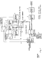
- Figure 1 shows a circuit structure of a prior art heterodyne detecting receiving apparatus used to achieve this positive control.
- the signal light transmitted through an optical fiber is inputted to mixing circuit 2 through polarization apparatus 1 and is then mixed with local oscillation light outputted from optical local oscillating circuit 3.
- the local oscillating light is assumed to be in a polarized state in which the principal axis angle is slanted, for example, by 45 degrees and the elliptic ratio is 1.
- One output signal from mixing circuit 2 is subjected to a heterodyne detection by optical receiver 4 and is converted to an intermediate frequency signal. This intermediate frequency signal is demodulated by demodulator 5 and outputted therefrom.
- the other output signal from mixing circuit 2 is used to monitor the polarization state of the signal light.
- the optical signal for monitoring is first divided into two portions by half mirror 6 and the transparent light is separated by polarization splitter 7 into two polarization components which intersect at right angles.
- the optical signal is thereafter converted into an electrical signal by optical receivers 8 and 9.
- the light reflected from half mirror 6 is subjected to a conversion of its polarization state by ⁇ /4 plate 10 (for example, a linearly polarized light is converted to a circularly polarized light or a circularly polarized light is converted into a linearly polarized light) and subsequently the reflected light is separated into two orthogonal polarization components by polarization splitter 11, whose axis is rotated 45 degrees from that of polarization splitter 7 and is thereafter converted into an electrical signal by optical receivers 12 and 13.
- the output signals from optical receivers 8 and 9 are inputted to differential amplifier 14 and the output signals from optical receivers 12 and 13 are inputted to the other differential amplifier 15.
- Differential amplifier signals A and B obtained from differential amplifiers 14 and 15 are used as monitor signals by polarization operation apparatus 1 to control the polarization state of the signal light.
- the principal axis angle of the polarization state of the signal light is controlled by making signal A equal to 0 and the elliptic ratio is controlled by making signal B equal to 0.
- a part of the signal light is divided into two portions by half mirror 6 and polarization splitters 7 and 11, and the polarization state of the signal light is monitored by four optical receivers 8, 9, 12 and 13, thus controlling the polarization state of the signal light.
- the structure of the optical system becomes complicated as half mirror 6, ⁇ /4 plate 10, the two polarization splitters 7 and 11, and the four optical receivers 8, 9, 12 and 13 must be used for merely monitoring the polarization state of signal light, even when optical receivers are required, resulting in the problem that the apparatus must be large. A part of the signal light is divided and used only for monitoring. Thus, the receiving sensitivity is deteriorated by an amount corresponding to the use of such a monitoring system. Further, there is a problem that the prior art apparatus cannot form a DBOR (Dual Balanced Optical Signal Receiver, refer to JP-A-1195153 (Japanese Patent Kokai No.
- JP-A-63238877 Japanese Patent Kokai No. 63-1124
- US Application No. 064058/87 EP-A-0 251 062
- EPC Application No. 87108787 EP-A-0 251 062
- CA-A-1290019 Canadian Application No. 539613/87) which makes it possible to perform a high-sensitivity receiving operation by using the signal component effectively suppressing the noise component.
- EP-A-0 245 026 discloses an optical heterodyne mixer providing image-frequency rejection and comprising a mixing optical device, a polarising splitter, respective photodetectors and a 90° image-frequency coupler.
- a signal light transmitted through a light transmission path is provided to mixing circuit 21 through polarization operating apparatus 20 and a local oscillation light from optical local oscillation circuit 22 is inputted to mixing circuit 21 in which a signal light is mixed with a local oscillation light.
- the polarization state of the local oscillation light is made to have its principle axis angle slanted by, for example, 45 degrees.
- the mixed light is separated by polarization splitter 23 into two orthogonal polarization components to each other.
- the components are subjected to respective heterodyne detections in optical receivers 24 and 25 to provide an intermediate frequency signal.
- the structure explained up to this point comprises an optical system.
- the polarization state of the signal light designates circular polarization light
- the polarization state of the signal light is made to show 45-degree or 135-degree linear polarization.
- the polarization state of the signal light is made to represent circular polarization light.
- the amplified beat components are obtained from ports P4 of 90-degree hybrid coupler 26 and the image components are outputted from port P3 to cancel each other out.
- the image component can be deleted from the intermediate frequency signal outputted from port P4 by driving polarization operating apparatus 20 by polarization control circuit 29 so that signal a is made 0 as described above.
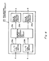
- Figure 7 shows a block diagram of the second embodiment of the present invention.
- This embodiment is formed of a DBOR (Dual Balanced Optical Reciver). Namely, another pair comprising polarization splitter 31 and optical receivers 32 and 33, having a structure similar to the aforementioned polarization splitter 23 and optical receivers 24 and 25, is provided to port P4 of mixing circuit 21 in the first embodiment. The output from optical receivers 24 and 32 are applied to subtractor 35.
- DBOR Double Balanced Optical Reciver
- the signal light is mixed with the local oscillation light in mixing circuit 21, and optical signals having a phase difference of 180 degrees are outputted from ports P3 and P4.
- These light signals are divided into equal parts by polarization splitters 23 and 31 and then subjected to heterodyne detection by light receivers 24, 25, 32 and 33.
- the intermediate frequency signal obtained by optical receivers 24 and 32 are applied to subtractor 34 and the intermediate signals obtained by optical receivers 25 and 33 are applied to subtractor 35.
- beat components having a 180-degree phase difference are inputted to optical receivers 24 and 32 and similarly beat components having a 180-degree phase difference are inputted to optical receivers 25 and 33.
- the beat components are added to be amplified and noise intensity components of the local oscillation light cancel each other in subtractors 34 and 35.
- the intermediate frequency signal in which the noise intensity component is suppressed is inputted to 90-degree hybrid coupler 26 and differential amplifier 28. Thereafter, the same process as in the first embodiment is continued.
- the present embodiment effectively utilizes two output lights from mixing circuit 21, thereby suppressing the excess intensity noise of the local oscillation light and greatly increasing the receiving sensitivity.
- the above embodiments describe the case where either the signal light or the local oscillation light is made to be in 45-degree (or 135-degree) linear polarization and the other is made to be in circular polarization. It is not always necessary to use the above arrangement. Namely, it is a required condition that both the signal light and local oscillation light be in a polarization state having their principal axes at 45 degrees, and that the phase difference between them be 90 degrees. Any polarization state satisfying the above condition may be used.
- the signal light may have elliptic polarization with 110-degree phase difference between the X components and Y components of the signal light
- the local oscillation light may have elliptic polarization with a phase difference of 20 degrees between the X and Y components of the local oscillation light.
- the circuit for inverting the signals from the power monitor 42 and the circuit for outputting the signal b by adding the output of the inverting circuit to the output from the power monitor 43 may be employed.
- polarization operating apparatus 20 instead of the structure shown in Figure 5, a wave guide device comprising an electrical optical crystal such as lithium niobate may be employed to perform a phase modulation by applying an appropriate voltage to the electrodes provided on the wave guide device, thereby enabling the polarization state of the signal light to be changed.
- a wave guide device comprising an electrical optical crystal such as lithium niobate may be employed to perform a phase modulation by applying an appropriate voltage to the electrodes provided on the wave guide device, thereby enabling the polarization state of the signal light to be changed.
- At least two optical receivers may be sufficient and thus, the structure of the optical system may be simplified and the apparatus as a whole may be miniaturized.
- the signal light is not divided merely for monitoring its polarization state and the polarization state may be monitored in the electrical signal stage. Therefore, a much higher sensitivity can be achieved upon receiving the signal light than in the prior art.
- the present invention may be easily formed using a DBOR, even higher sensitivity reception is possible.
- the image component may be deleted from the other output signal.
Landscapes
- Physics & Mathematics (AREA)
- Electromagnetism (AREA)
- Engineering & Computer Science (AREA)
- Computer Networks & Wireless Communication (AREA)
- Signal Processing (AREA)
- Optical Communication System (AREA)
Claims (27)
- Appareil de réception hétérodyne pour une communication optique cohérente, comprenant:un circuit d'oscillation locale optique (22) pour produire une lumière d'oscillation locale;un appareil d'opération de polarisation (20) pour faire varier l'état de polarisation d'une lumière de signal sur une voie de transmission de lumière ;un circuit de mélange (21) pour mélanger une lumière de signal ayant son état de polarisation corrigé par ledit moyen d'opération de polarisation (20) avec une lumière d'oscillation locale émise en sortie depuis ledit circuit d'oscillation locale optique (22) ;un séparateur de polarisation (23) pour séparer une lumière de sortie provenant dudit circuit de mélange (21) en deux types de composantes de polarisation ;des récepteurs optiques (24, 25) pour détecter des signaux pour chaque composante de polarisation obtenue depuis ledit séparateur de polarisation (23) pour produire un signal de fréquence intermédiaire ;un moyen (27) pour combiner deux signaux de fréquence intermédiaire émis en sortie depuis lesdits récepteurs optiques (24, 25) ;un démodulateur (27) pour démoduler un premier signal de sortie émis en sortie depuis ledit moyen de combinaison de signal (26) ; etun circuit de commande de polarisation (29) pour commander l'état de polarisation de ladite sortie de signal en activant ledit appareil d'opération de polarisation (20) sur la base de second et troisième signaux de sortie (b, a) respectivement dérivés depuis lesdits récepteurs optiques (24, 25) et depuis ledit moyen de combinaison de signal (27),caractérisé en ce que ledit moyen de combinaison de signal (26) comprend un coupleur hybride à 90 degrés (26) pour combiner lesdits signaux de fréquence intermédiaire émis en sortie depuis lesdits récepteurs optiques (24, 25) pour produire, au niveau d'un port de sortie (P3), ledit troisième signal de sortie (a) et au niveau d'un second port de sortie (P4), un signal de fréquence intermédiaire pour l'émettre en sortie sur ledit démodulateur (27) en tant que dit premier signal de sortie.
- Appareil de réception hétérodyne selon la revendication 1, dans lequel :à la fois la lumière de signal et la lumière d'oscillation locale ont leurs angles d'axes principaux inclinés de 45 degrés et la différence de phase entre eux est de 90 degrés.
- Appareil de réception hétérodyne selon la revendication 1 ou 2, dans lequel :le circuit d'oscillation locale optique (22) est un laser à semiconducteur.
- Appareil de réception hétérodyne selon la revendication 1, 2 ou 3, dans lequel :ledit appareil d'opération de polarisation (20) comprend une lame quart d'onde (20a) et une lame demi-onde (20b) agencées en série sur le chemin optique de la lumière de signal, et un moteur impulsionnel (20c, 20d) pour faire tourner et entraîner chacune d'elles.
- Appareil de réception hétérodyne selon l'une quelconque des revendications précédentes, dans lequel :ledit séparateur de polarisation (23) divise la lumière de sortie dudit circuit de mélange en deux composantes de polarisation orthogonales.
- Appareil de réception hétérodyne selon l'une quelconque des revendications précédentes, dans lequel :ledit récepteur optique (26) comprend une photodiode pour réaliser une détection hétérodyne sur un signal correspondant à des composantes de polarisation respectives obtenues par ladite polarisation et pour produire des signaux intermédiaires dont des phases diffèrent de 90 degrés.
- Appareil de réception hétérodyne selon l'une quelconque des revendications précédentes, dans lequel ledit coupleur hybride à 90 degrés (26) comporte des premier et second ports d'entrée (P1, P2) en plus desdits premier et second ports de sortie (P3, P4), lesdits ports d'entrée et de sortie (P1, P2, P3, P4) servant à retarder la phase du signal entré sur le premier port d'entrée (P1) de 90 degrés, à additionner le signal retardé au signal reçu par le second port de sortie (P4), à retarder de 90 degrés la phase du signal reçu par le second port d'entrée (P2) et à appliquer le signal retardé sur le signal reçu par le premier port d'entrée (P1) et à ainsi l'émettre en sortie depuis le premier port de sortie (P3).
- Appareil de réception hétérodyne selon la revendication 7, dans lequel ledit coupleur hybride à 90 degrés (26) est agencé pour additionner les signaux de fréquence intermédiaire qui sont émis en sortie depuis lesdits récepteurs optiques et qui sont décalés en phase de 90 degrés, et les signaux de fréquence intermédiaire qui sont rendus égaux en phase, pour ainsi les émettre en sortie depuis le second port de sortie (P4) pour qu'ils soient transmis sur ledit démodulateur (27), et pour également émettre en sortie en tant que moyen de surveillance les signaux de fréquence intermédiaire qui sont amenés à présenter des phases opposées et qui sont additionnés les uns aux autres, depuis le premier port de sortie (P3).
- Appareil de réception hétérodyne selon la revendication 8, dans lequel les signaux émis en sortie en tant que moyen de surveillance depuis le premier port de sortie (P3) du coupleur hybride à 90 degrés (26) sont rendus égaux à zéro ou à une valeur minimum et la composante d'image est ôtée du signal émis en sortie depuis le second port de sortie (P4) du coupleur hybride à 90 degrés (26).
- Appareil de réception hétérodyne selon l'une quelconque des revendications précédentes, dans lequel un amplificateur différentiel (28) est prévu pour recevoir les signaux de sortie provenant des deux récepteurs optiques, le signal émis en sortie depuis ledit amplificateur différentiel est constitué en tant que signal permettant de surveiller l'angle d'axe principal de la lumière de signal, le signal émis en sortie depuis le premier port de sortie (P3) dudit coupleur hybride à 90 degrés (26) est constitué en tant que signal permettant de surveiller le rapport elliptique de la lumière de signal et ledit circuit de polarisation et de commande (29) est agencé pour recevoir le signal (b) pour le moyen de surveillance d'angle d'axe principal et le signal (a) pour surveiller le rapport elliptique.
- Appareil de réception hétérodyne selon la revendication 10, dans lequel le circuit de commande de polarisation (29) est agencé pour activer ledit appareil d'opération de polarisation (20) de telle sorte que les deux signaux (b, a) pour surveiller ledit angle d'axe principal et des signaux pour surveiller le rapport elliptique soient rendus égaux à zéro ou à une valeur minimum.
- Appareil de réception hétérodyne selon la revendication 11, dans lequel ledit circuit de commande de polarisation (29) comprend des convertisseurs analogiques/numériques (A/N) respectifs (29b, 29a) pour réaliser une conversion A/N de signaux pour surveiller l'angle d'axe principal et du signal pour surveiller le rapport elliptique, des circuits d'activation de moteur impulsionnel respectifs (29e, 29d) pour entraîner lesdits moteurs impulsionnels (20d, 20c) pour ledit appareil d'opération de polarisation (20) et un circuit d'opération de valeur numérique (29c) pour commander lesdits circuits d'entraînement de moteur impulsionnel (29e, 29d) de telle sorte que les sorties desdits convertisseurs A/N (29b, 29a) soit rendues égales à zéro ou à un minimum.
- Appareil de réception hétérodyne selon la revendication 12, dans lequel ledit circuit d'opération de valeur numérique (29c) traite les données numériques conformément à un algorithme d'escalade de montagne.
- Appareil de réception hétérodyne selon la revendication 10, dans lequel le signal de sortie provenant du premier port de sortie (P3) provenant dudit coupleur hybride à 90 degrés (26) et les signaux de sortie provenant des récepteurs optiques (24, 25) sont appliqués sur ledit circuit de commande de polarisation (29) et sur ledit amplificateur différentiel (28) par l'intermédiaire de moniteurs de puissance respectifs (41, 42, 43) pour détecter la puissance.
- Appareil de réception hétérodyne destiné à être utilisé lors d'une communication optique cohérente, comprenant :un circuit d'oscillateur local optique (22) pour faire osciller une lumière d'oscillation locale;un moyen d'opération de polarisation (20) pour faire varier l'état de polarisation du signal transmis sur une voie de transmission optique ;un circuit de mélange (21) pour mélanger la lumière de signal dont l'état de polarisation est corrigé par le circuit d'opération de polarisation (20) avec ladite lumière d'oscillation émise en sortie depuis ledit circuit de lumière d'oscillation locale (22) et pour diviser les signaux de lumière mélangés selon deux signaux de lumière présentant une différence de phase de 180 degrés pour qu'ils soient émis en sortie depuis des premier et second ports de sortie (P3, P4) du circuit de mélange (21) ;un premier séparateur de polarisation (23) pour diviser la lumière émise en sortie depuis le premier port de sortie (P3) du circuit de mélange en deux composantes orthogonales ;des premier et second récepteurs optiques (23, 25) pour appliquer une détection hétérodyne à des signaux de composantes de polarisation respectives obtenues depuis le premier séparateur de polarisation (23) et pour émettre en sortie un signal de fréquence intermédiaire ;un second séparateur de polarisation (31) pour diviser la lumière émise en sortie depuis le second port de sortie (P4) du circuit de mélange (21) selon deux composantes de polarisation orthogonales ;des troisième et quatrième récepteurs optiques (32, 33) pour réaliser une détection hétérodyne des signaux de la composante de polarisation sélective obtenue depuis le second séparateur de polarisation (31) et pour émettre en sortie un signal de fréquence intermédiaire ;un premier soustracteur (34) pour soustraire la sortie du premier récepteur optique (24) de la sortie du troisième récepteur optique (32);un second soustracteur (35) pour soustraire la sortie du second récepteur de lumière (25) de la sortie du quatrième récepteur de lumière (33);un moyen (26) pour combiner deux signaux de fréquence intermédiaire émis en sortie depuis lesdits premier et second soustracteurs (34, 35) ;un démodulateur (27) pour démoduler un premier signal de sortie émis en sortie depuis ledit moyen de combinaison de signal (26) ; etun circuit de commande de polarisation (29) pour activer l'appareil d'opération de polarisation (20) sur la base de second et troisième signaux de sortie (b, a) respectivement dérivés depuis lesdits premier et second soustracteurs (34, 35) et depuis ledit moyen de combinaison (26), pour commander le statut de polarisation de la lumière de signal en constituant ainsi un récepteur optique équilibré double,caractérisé en ce que ledit moyen de combinaison de signal (26) comprend un coupleur hybride à 90 degrés (26) pour combiner lesdits signaux de fréquence intermédiaire émis en sortie depuis lesdits premier et second soustracteurs (34, 35), pour produire, au niveau d'un port de sortie (P3), ledit troisième signal de sortie (a) et, au niveau d'un second port de sortie (P4), un signal de fréquence intermédiaire pour l'émettre en sortie sur ledit démodulateur (27) en tant que dit premier signal de sortie.
- Appareil de réception hétérodyne selon la revendication 15, dans lequel à la fois une lumière de signal et une lumière d'oscillation locale présentent des états de polarisation selon lesquels les axes principaux sont inclinés de 45 degrés et présentent une différence de phase de 90 degrés.
- Appareil de réception hétérodyne selon la revendication 15 ou 16, dans lequel ledit circuit d'oscillateur local optique (22) comprend un laser à semiconducteur.
- Appareil de réception hétérodyne selon la revendication 15, 16 ou 17, dans lequel ledit appareil d'opération de polarisation (20) comprend une lame quart d'onde (20a) et une lame demi-onde (20b) agencées en série le long de la voie de la lumière de signal et un moteur impulsionnel (20c, 20d) pour faire tourner chacune des lames quart d'onde et demi-onde (20a, 20b).
- Appareil de réception hétérodyne selon l'une quelconque des revendications 15 à 18, dans lequel :lesdits premier à quatrième récepteurs optiques (24, 25, 32, 33) comprennent des photodiodes, et des signaux des composantes de polarisation de lumière respectives obtenues par lesdits premier et second séparateurs de polarisation (23, 31) sont soumis à une détection hétérodyne pour ainsi produire des signaux de fréquence intermédiaire dont des phases sont décalées de 90 degrés l'une par rapport à l'autre.
- Appareil de réception hétérodyne selon l'une quelconque des revendications 15 à 19, dans lequel ledit coupleur hybride à 90 degrés (26) comporte des premier et second ports d'entrée (P1, P2) en plus desdits premier et second ports de sortie (P3, P4) et retarde la phase du signal entré sur le premier port d'entrée (P1), le signal retardé est additionné aux signaux entrés sur le second port d'entrée (P2) et ils sont ainsi émis en sortie depuis le second port de sortie (P4), la phase du signal entré sur le second port d'entrée (P2) est retardée de 90 degrés et le signal retardé est additionné au signal entré sur le premier port d'entrée (P1) pour être émis en sortie depuis le premier port de sortie (P3).
- Appareil de réception hétérodyne selon la revendication 20, dans lequel ledit coupleur hybride à 90 degrés (26) est agencé pour additionner les signaux de fréquence intermédiaire émis en sortie depuis les soustracteurs (34, 35), lesdits signaux présentant une différence de phase de 90 degrés et étant modifiés de manière à présenter la même phase, d'où ainsi la production d'un signal additionné qui est émis en sortie depuis le second port de sortie (P4) et qui est transmis sur le démodulateur (27), et les signaux de fréquence intermédiaire qui sont décalés en phase de 90 degrés les uns par rapport aux autres sont constitués pour former un signal de la phase opposée et sont additionnés les uns aux autres pour être ainsi émis en sortie depuis le premier port de sortie (P3) en tant que signal de surveillance.
- Appareil de réception hétérodyne selon la revendication 21, dans lequel le signal émis en sortie depuis le premier port de sortie (P3) dudit coupleur hybride à 90 degrés (26) émis en sortie en tant que moyen de surveillance est rendu égal à 0 ou à une valeur minimum pour ainsi supprimer la composante d'image des signaux émis en sortie depuis le second port de sortie (P4).
- Appareil de réception hétérodyne selon la revendication 20, dans lequel un amplificateur différentiel (28) est prévu pour recevoir les signaux de sortie provenant des premier et second soustracteurs (34, 35), le signal émis en sortie depuis l'amplificateur différentiel (28) est constitué en tant que signal pour surveiller l'angle d'axe principal de la lumière de signal et le signal émis en sortie depuis le premier port de sortie (P3) du coupleur hybride à 90 degrés (26) est constitué en tant que signal pour surveiller un rapport elliptique de la lumière de signal, ledit circuit de commande de polarisation (29) étant agencé pour recevoir des signaux (b) pour surveiller un angle principal et des signaux (a) pour surveiller le rapport elliptique.
- Appareil de réception hétérodyne selon la revendication 23, dans lequel le circuit de commande de polarisation (29) est agencé pour activer l'appareil d'opération de polarisation (20) de telle sorte qu'à la fois les signaux (b) pour surveiller l'angle d'axe principal et les signaux (a) pour surveiller le rapport elliptique soient rendus égaux à 0 ou à un maximum.
- Appareil de réception hétérodyne selon la revendication 24, dans lequel le circuit de commande de polarisation (29) comprend des convertisseurs A/N respectifs (29b, 29a) pour réaliser une conversion A/N dudit signal de surveillance d'angle principal et dudit signal de surveillance de rapport elliptique, des circuits d'entraînement de moteur impulsionnel respectifs (29e, 29d) pour entraîner les moteurs impulsionnels (20d, 20c) de l'appareil d'opération de polarisation (20) et un circuit de traitement numérique pour commander le circuit d'entraînement de moteur impulsionnel (29c) de telle sorte que toutes les sorties desdits convertisseurs A/N (29b, 29a) soient rendues égales à 0 ou à un minimum.
- Appareil de réception hétérodyne selon la revendication 25, dans lequel le circuit de traitement numérique (29c) est soumis à un processus numérique utilisant un procédé d'escalade de montagne.
- Appareil de réception hétérodyne selon la revendication 23, dans lequel le signal de sortie provenant du premier port de sortie (P3) dudit coupleur hybride à 90 degrés (26) et les signaux de sortie provenant des soustracteurs (34, 35) sont respectivement appliqués à un circuit de commande de polarisation (29) et à un amplificateur différentiel (28) par l'intermédiaire de la détection de puissance réalisée par des moniteurs de puissance (41, 42, 43).
Applications Claiming Priority (2)
| Application Number | Priority Date | Filing Date | Title |
|---|---|---|---|
| JP262943/88 | 1988-10-20 | ||
| JP63262943A JPH0734080B2 (ja) | 1988-10-20 | 1988-10-20 | コヒーレント光通信用ヘテロダイン検波受信装置 |
Publications (3)
| Publication Number | Publication Date |
|---|---|
| EP0365028A2 EP0365028A2 (fr) | 1990-04-25 |
| EP0365028A3 EP0365028A3 (fr) | 1991-12-27 |
| EP0365028B1 true EP0365028B1 (fr) | 1996-01-24 |
Family
ID=17382721
Family Applications (1)
| Application Number | Title | Priority Date | Filing Date |
|---|---|---|---|
| EP89119515A Expired - Lifetime EP0365028B1 (fr) | 1988-10-20 | 1989-10-20 | Récepteur hétérodyne pour communication optique cohérente |
Country Status (4)
| Country | Link |
|---|---|
| US (1) | US5052051A (fr) |
| EP (1) | EP0365028B1 (fr) |
| JP (1) | JPH0734080B2 (fr) |
| CA (1) | CA2000997C (fr) |
Families Citing this family (32)
| Publication number | Priority date | Publication date | Assignee | Title |
|---|---|---|---|---|
| US5258615A (en) * | 1990-08-03 | 1993-11-02 | Gpt Limited | Optical fiber monitoring by detection of polarization variations |
| JPH04150628A (ja) * | 1990-10-15 | 1992-05-25 | Nec Corp | 光通信システムの波長安定化方法および回路 |
| NL9002713A (nl) * | 1990-12-10 | 1992-07-01 | Nederland Ptt | Transmissiesysteem voor de polarisatie-ongevoelige overdracht van signalen. |
| JP3183685B2 (ja) * | 1991-09-13 | 2001-07-09 | 富士通株式会社 | 光通信システム |
| JP2776124B2 (ja) * | 1992-03-23 | 1998-07-16 | 日本電気株式会社 | 直接検波光受信装置 |
| JPH05303128A (ja) * | 1992-04-27 | 1993-11-16 | Nec Corp | イメージ信号除去光ヘテロダイン検波受信装置 |
| JPH07281229A (ja) * | 1994-04-13 | 1995-10-27 | Ando Electric Co Ltd | 光偏波制御装置 |
| US5574553A (en) * | 1994-12-27 | 1996-11-12 | The United States Of America As Represented By The Secretary Of The Air Force | Ladar receiver incorporating an optical amplifier and polarization optical mixer |
| US5574589A (en) * | 1995-01-09 | 1996-11-12 | Lucent Technologies Inc. | Self-amplified networks |
| DE59700214D1 (de) * | 1996-11-25 | 1999-07-22 | Contraves Ag | Verfahren und Vorrichtung zur optischen Uebertragung von Daten über Freiraumstrecken |
| ATE298478T1 (de) | 1998-12-22 | 2005-07-15 | Contraves Space Ag | Verfahren und vorrichtung zur erzeugung eines fehlersignals bei kohärentem überlagerungsempfang von lichtwellen |
| JP2003502902A (ja) * | 1999-06-10 | 2003-01-21 | ファイバースペイス,インコーポレーテッド | 光伝送の所与の帯域を選択するための高周波/マイクロ波および光混合技術を使用するための方法および装置 |
| US6850710B1 (en) | 2000-06-09 | 2005-02-01 | Tip Group, Llc | Method and apparatus of utilizing RF/microwave and optical mixing techniques to select a given band of an optical transmission |
| US7006562B2 (en) * | 2000-03-17 | 2006-02-28 | Chien Chou | Phase demodulator, phase difference detector, and interferometric system using the phase difference detector |
| US6459826B1 (en) * | 2000-03-21 | 2002-10-01 | Lucent Technologies Inc. | Programmable optical switch apparatus |
| US7903982B2 (en) * | 2004-04-15 | 2011-03-08 | Mitsubishi Electric Corporation | Optical receiver |
| US7330669B2 (en) * | 2004-04-20 | 2008-02-12 | Lucent Technologies Inc. | Optical heterodyne receiver based on oversampling |
| JP2006013573A (ja) * | 2004-06-22 | 2006-01-12 | Hitachi Ltd | 量子光伝送装置 |
| JP4170298B2 (ja) * | 2005-01-31 | 2008-10-22 | 富士通株式会社 | 差分4位相偏移変調方式に対応した光受信器および光受信方法 |
| US7561813B2 (en) * | 2005-06-09 | 2009-07-14 | Northrop Grumman Corporation | Wide field of view heterodyne receiver |
| US7406269B2 (en) * | 2006-03-10 | 2008-07-29 | Discovery Semiconductors, Inc. | Feedback-controlled coherent optical receiver with electrical compensation/equalization |
| US7809284B2 (en) * | 2006-06-23 | 2010-10-05 | Alcatel-Lucent Usa Inc. | System and method for receiving coherent, polarization-multiplexed optical signals |
| US8233798B2 (en) * | 2007-09-25 | 2012-07-31 | Levinson Frank H | Parallel transmission of data streams in a star-configured network |
| EP2388935A1 (fr) * | 2010-05-19 | 2011-11-23 | Nokia Siemens Networks Oy | Unité de réseau optique, procédé de traitement de données dans un réseau optique et système de communication |
| WO2013042345A1 (fr) * | 2011-09-22 | 2013-03-28 | 日本電気株式会社 | Dispositif de traitement de signal optique, dispositif de traitement de polarisation et procédé de traitement de signal optique |
| JP5278574B1 (ja) * | 2012-03-30 | 2013-09-04 | 住友大阪セメント株式会社 | 光90度ハイブリッド回路及びそれを用いた光受信器 |
| US9337937B2 (en) | 2014-03-10 | 2016-05-10 | Cisco Technology, Inc. | Common mode rejection ratio control for coherent optical receivers |
| EP3661080B1 (fr) * | 2017-07-25 | 2021-09-01 | KDDI Corporation | Récepteur optique et procédé de réception optique cohérente |
| US10833767B2 (en) * | 2018-01-24 | 2020-11-10 | Indian Institute Of Technology Bombay | Self-homodyne carrier multiplexed transmission system and method for coherent optical links |
| CN110868258B (zh) * | 2018-08-27 | 2022-08-16 | 中兴通讯股份有限公司 | 一种相干检测的实现装置、系统及方法 |
| CN112640329B (zh) * | 2018-09-07 | 2025-01-03 | 日本电气株式会社 | 光学接收器和接收方法 |
| EP3886342A1 (fr) * | 2020-03-24 | 2021-09-29 | Mitsubishi Electric R & D Centre Europe B.V. | Récepteur optique cohérent |
Family Cites Families (5)
| Publication number | Priority date | Publication date | Assignee | Title |
|---|---|---|---|---|
| JPS6123121A (ja) * | 1984-07-12 | 1986-01-31 | Nec Corp | 光ヘテロダイン受信方法 |
| GB8514264D0 (en) * | 1985-06-06 | 1985-07-10 | British Telecomm | Coherent optical receivers |
| US4723317A (en) * | 1986-05-08 | 1988-02-02 | American Telephone And Telegraph Company, At&T Bell Laboratories | Optical heterodyne mixers providing image-frequency rejection |
| DE3621734A1 (de) * | 1986-06-28 | 1988-01-07 | Standard Elektrik Lorenz Ag | Optischer ueberlagerungsempfaenger |
| DE3880248T2 (de) * | 1987-09-28 | 1993-10-28 | Philips Nv | Anordnung für optische Heterodyn- oder Homodyndetektion eines optischen Signalstrahls und Empfänger mit einer derartigen Anordnung. |
-
1988
- 1988-10-20 JP JP63262943A patent/JPH0734080B2/ja not_active Expired - Lifetime
-
1989
- 1989-10-19 CA CA002000997A patent/CA2000997C/fr not_active Expired - Fee Related
- 1989-10-20 US US07/424,732 patent/US5052051A/en not_active Expired - Fee Related
- 1989-10-20 EP EP89119515A patent/EP0365028B1/fr not_active Expired - Lifetime
Also Published As
| Publication number | Publication date |
|---|---|
| CA2000997C (fr) | 1994-02-08 |
| US5052051A (en) | 1991-09-24 |
| EP0365028A2 (fr) | 1990-04-25 |
| JPH02110524A (ja) | 1990-04-23 |
| JPH0734080B2 (ja) | 1995-04-12 |
| EP0365028A3 (fr) | 1991-12-27 |
| CA2000997A1 (fr) | 1990-04-20 |
Similar Documents
| Publication | Publication Date | Title |
|---|---|---|
| EP0365028B1 (fr) | Récepteur hétérodyne pour communication optique cohérente | |
| US4817206A (en) | Optical-fiber transmission system with polarization modulation and heterodyne coherent detection | |
| EP0409260B1 (fr) | Récepteur pour communication optique cohérente | |
| EP0352747B1 (fr) | Procédé de stabilisation d'une séparation de fréquence pour communication optique hétérodyne ou homodyne | |
| US8014685B2 (en) | Coherent optical receiver | |
| US10693563B2 (en) | Coherent optical receiver | |
| US5060312A (en) | Polarization independent coherent lightwave detection arrangement | |
| CN101917233B (zh) | 一种适用于相干检测的全光相位噪声抑制方法 | |
| EP0467358B1 (fr) | Démodulateur et récepteur à diversité de polarisation pour communication optique cohérente comprenant le démodulateur | |
| EP0245026B1 (fr) | Mélangeur optique hétérodyne procurant une réjection des fréquences-images | |
| CA1308440C (fr) | Methode de communication optique a diversite de polarisation et appareil utilisant cette methode | |
| EP0456365A2 (fr) | Hybride optique pour des systèmes de détection cohérents | |
| JPH09281537A (ja) | 偏光制御回路 | |
| EP0519491A1 (fr) | Discriminateur de fréquence et récepteur hétérodyne pourvus d'un discriminateur pour communications cohérentes de lumière | |
| JPS63224427A (ja) | 偏波ダイバシテイ光受信方法及びその装置 | |
| JP2974077B2 (ja) | コヒーレント光通信用受信装置 | |
| JPH05191351A (ja) | ヘテロダイン受信器 | |
| JP2668410B2 (ja) | イメージリジェクションミキサ | |
| JPH03259632A (ja) | 光ヘテロダイン偏波ダイバーシティ受信器 | |
| JPH0226146A (ja) | 光ヘテロダイン検波回路 | |
| JPH0593935A (ja) | 偏波状態制御方法 | |
| JPH02137425A (ja) | コヒーレント光通信方式 | |
| JPH03116120A (ja) | 光受信回路 | |
| JPH05257185A (ja) | 光受信装置 | |
| JPH01183929A (ja) | 光波通信装置 |
Legal Events
| Date | Code | Title | Description |
|---|---|---|---|
| PUAI | Public reference made under article 153(3) epc to a published international application that has entered the european phase |
Free format text: ORIGINAL CODE: 0009012 |
|
| AK | Designated contracting states |
Kind code of ref document: A2 Designated state(s): DE FR GB |
|
| PUAL | Search report despatched |
Free format text: ORIGINAL CODE: 0009013 |
|
| AK | Designated contracting states |
Kind code of ref document: A3 Designated state(s): DE FR GB |
|
| 17P | Request for examination filed |
Effective date: 19920305 |
|
| 17Q | First examination report despatched |
Effective date: 19940117 |
|
| RBV | Designated contracting states (corrected) |
Designated state(s): FR GB |
|
| REG | Reference to a national code |
Ref country code: DE Ref legal event code: 8566 |
|
| GRAA | (expected) grant |
Free format text: ORIGINAL CODE: 0009210 |
|
| AK | Designated contracting states |
Kind code of ref document: B1 Designated state(s): FR GB |
|
| ET | Fr: translation filed | ||
| PLBE | No opposition filed within time limit |
Free format text: ORIGINAL CODE: 0009261 |
|
| STAA | Information on the status of an ep patent application or granted ep patent |
Free format text: STATUS: NO OPPOSITION FILED WITHIN TIME LIMIT |
|
| 26N | No opposition filed | ||
| PGFP | Annual fee paid to national office [announced via postgrant information from national office to epo] |
Ref country code: FR Payment date: 20001010 Year of fee payment: 12 |
|
| PGFP | Annual fee paid to national office [announced via postgrant information from national office to epo] |
Ref country code: GB Payment date: 20001018 Year of fee payment: 12 |
|
| PG25 | Lapsed in a contracting state [announced via postgrant information from national office to epo] |
Ref country code: GB Free format text: LAPSE BECAUSE OF NON-PAYMENT OF DUE FEES Effective date: 20011020 |
|
| REG | Reference to a national code |
Ref country code: GB Ref legal event code: IF02 |
|
| GBPC | Gb: european patent ceased through non-payment of renewal fee |
Effective date: 20011020 |
|
| PG25 | Lapsed in a contracting state [announced via postgrant information from national office to epo] |
Ref country code: FR Free format text: LAPSE BECAUSE OF NON-PAYMENT OF DUE FEES Effective date: 20020628 |
|
| REG | Reference to a national code |
Ref country code: FR Ref legal event code: ST |