EP0366380B1 - Bildabtast- und Druckvorrichtung - Google Patents
Bildabtast- und Druckvorrichtung Download PDFInfo
- Publication number
- EP0366380B1 EP0366380B1 EP89310872A EP89310872A EP0366380B1 EP 0366380 B1 EP0366380 B1 EP 0366380B1 EP 89310872 A EP89310872 A EP 89310872A EP 89310872 A EP89310872 A EP 89310872A EP 0366380 B1 EP0366380 B1 EP 0366380B1
- Authority
- EP
- European Patent Office
- Prior art keywords
- scanning
- printing
- recording medium
- linear
- printing apparatus
- Prior art date
- Legal status (The legal status is an assumption and is not a legal conclusion. Google has not performed a legal analysis and makes no representation as to the accuracy of the status listed.)
- Expired - Lifetime
Links
Images


Classifications
-
- H—ELECTRICITY
- H04—ELECTRIC COMMUNICATION TECHNIQUE
- H04N—PICTORIAL COMMUNICATION, e.g. TELEVISION
- H04N1/00—Scanning, transmission or reproduction of documents or the like, e.g. facsimile transmission; Details thereof
- H04N1/04—Scanning arrangements, i.e. arrangements for the displacement of active reading or reproducing elements relative to the original or reproducing medium, or vice versa
- H04N1/207—Simultaneous scanning of the original picture and the reproduced picture with a common scanning device
-
- H—ELECTRICITY
- H04—ELECTRIC COMMUNICATION TECHNIQUE
- H04N—PICTORIAL COMMUNICATION, e.g. TELEVISION
- H04N1/00—Scanning, transmission or reproduction of documents or the like, e.g. facsimile transmission; Details thereof
- H04N1/46—Colour picture communication systems
- H04N1/48—Picture signal generators
- H04N1/482—Picture signal generators using the same detector device sequentially for different colour components
-
- H—ELECTRICITY
- H04—ELECTRIC COMMUNICATION TECHNIQUE
- H04N—PICTORIAL COMMUNICATION, e.g. TELEVISION
- H04N1/00—Scanning, transmission or reproduction of documents or the like, e.g. facsimile transmission; Details thereof
- H04N1/46—Colour picture communication systems
- H04N1/50—Picture reproducers
- H04N1/506—Reproducing the colour component signals picture-sequentially, e.g. with reproducing heads spaced apart from one another in the subscanning direction
- H04N1/508—Reproducing the colour component signals picture-sequentially, e.g. with reproducing heads spaced apart from one another in the subscanning direction using the same reproducing head for two or more colour components
Definitions
- This invention relates to a scanning and printing apparatus, such as a copier or facsimile machine, for flatbed scanning of documents and printing of document images.
- a scanning and printing apparatus is the electrophotographic copier in which a document is placed face-down on a glass window called a copyboard, a cover is closed over the document, and the document is scanned by a movable scanning unit disposed below the copyboard.
- the scanning unit converts the image on the document to electrical signals which are sent to a printing unit comprising, for example, a rotating drum, a toner developing system, and a paper cassette.
- a printing unit comprising, for example, a rotating drum, a toner developing system, and a paper cassette.
- Color copiers comprising a thermal or ink-jet printing unit have also been developed.
- a typical color copier of this type scans a document three times, once for each of three primary colors, and transports the paper through the printing unit three times to have each color printed separately. Since the scanning speed is not in general equal to the printing speed, a buffer memory is needed to store the signal from the scanning unit before they are printed by the printing unit. It may further be necessary to process the signals sent from the scanning unit to the printing unit to compensate for differences between the spectral characteristics of the filters in the scanning unit and the inks in the printing unit.
- a facsimile machine is similar in function, except that instead of sending electrical signals from its scanning unit to its printing unit, a facsimile machine sends signals from its scanning unit to a distant facsimile machine and prints images received from a distant facsimile machine.
- EP-A-0119166 discloses a method and apparatus for reproducing colored images in which a recording paper sheet is moved by a platen roller past a fixed print head in synchronism with the scanning movement of a scanning carriage.
- US-A-4517591 employs a rotating drum upon which recording paper is mounted and the drum rotates whilst the document is scanned.
- an associated problem is that to prevent distortion of the copied image, the speed of the driving system for the scanning unit must be accurately related to the speed of the driving system for paper transport in the printing unit. Expensive, high-precision stepping motors must therefore be used in these driving systems and, even so, distortion may occur due to vibration of the apparatus, or to motor irregularities.
- An object of the invention is accordingly to simplify the structure of a scanning and printing apparatus.
- Another object is to solve problems of synchronization of scanning and printing speeds.
- a scanning and printing apparatus for flatbed scanning of documents and printing images of documents as defined in appended claim 1, comprising : driving means for generating a linear, reciprocal scanning motion; linear scanning means arranged to scan in a direction transverse to said reciprocal motion, said linear scanning means being also coupled to and reciprocally moved by said driving means, thereby to scan a document and convert an image thereof into electrical signals; printing means responsive to electrical signals of an image to be printed and adapted to print said image on a recording medium, the electrical signals being provided either by said linear scanning means or from an external scanning means of another distant facsimile machine; clamping means attached to the scanning means to be reciprocally moved by said driving means simultaneous with the linear scanning means, said clamping means cooperating with a platen roller which is arranged at a fixed position and driven in accordance with the direction of motion of the clamping means, whereby said clamping means can hold one edge of said recording medium and, in cooperation with said platen roller, move said recording medium without buckling past said printing means in a reciproc
- the linear scanning means may comprise line sensor means.
- the invention provides a method of scanning documents and of printing images on a recording medium as defined in appended claim 14, said method comprising operating driving means to move linear scanning means in a reciprocal manner in first and second mutually opposed directions and operating the linear scanning means to scan in a direction transverse to said directions in relation to a document to convert images thereon into electrical signals; driving clamping means attached to the scanning means for movement by the same driving means, the clamping means holding one edge of a recording medium ; and operating the clamping means in co-operation with a platen roller to move the recording medium in a reciprocal manner without buckling past a printing means and operating the printing means to print an image on the recording medium in accordance with said electrical signals provided by the linear scanning means or in accordance with electrical signals provided from an external scanning means of another distant facsimile machine.
- Figure 1 is a sectional view of a monochrome scanning and printing apparatus.
- Fig. 2 is a sectional view of a color scanning and printing apparatus.
- Fig. 3 is a more detailed, schematic view of the image sensor in Fig. 2.
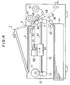
- Fig. 4 is a sectional view of another color scanning and printing apparatus.
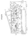
- Fig. 5 is a sectional view of yet another color scanning and printing apparatus.
- the novel scanning and printing apparatus illustrated in Fig. 1 is a monochrome copier for making a black-and-white copy of a document.
- the apparatus has a cover 1 which can be opened to permit a document 2 to be placed face-down on a copyboard 3.
- the copyboard 3 is a sheet of transparent material such as glass.
- the scanning and printing apparatus comprises a driving means, a scanning means, a clamping means, and a printing means.
- the driving means in Fig. 1 comprises a motor 11, a belt 12, a first pulley 13, a second pulley 14, and a wire 15.
- the motor 11, which may be a stepping motor for example, is controlled so as to turn in first one direction, then the opposite direction.
- the motor 11 drives the belt 12 which turns the first pulley 13, thus generating a linear, reciprocating motion of the wire 15 which is strung on the first and second pulleys 13 and 14.
- the scanning means is coupled to and reciprocally moved by the driving means so as to scan the document 2.
- the scanning means comprises a guide rail 21, a carriage 22, and a contact-type line sensor 23.
- the carriage 22 is movably mounted on the guide rail 21 and attached to the two ends of the wire 15.
- the contact-type line sensor 23 is rigidly mounted on the carriage 22.
- the contact-type line sensor 23 comprises, for example, a linear array of rod lenses 24 and photodetector elements 25. Light generated by light sources 26 is reflected from the document 2 and channeled by the rod lenses 24 to the photodetector elements 25, which generate electrical signals representative of the intensity of the received light. At a given position of the carriage 22, the photodetector elements 25 thus generate signals representing the intensity of a line of adjacent dot-shaped areas extending laterally across the document 2. By moving lengthwise along the document 2, the contact-type line sensor 23 converts an image of the entire document 2 to electrical signals.
- the clamping means is also coupled to and reciprocally moved by the driving means.
- the clamping means comprises a lever 31 attached to the carriage 22 and actuated by a well-known mechanism such as a spring and electromagnet, which are not shown in the drawing.
- the function of the lever 31 is to hold one edge of a recording medium 35 such as a sheet of paper, thereby moving the recording medium 35 in a reciprocal manner.
- the printing means prints an image on the recording medium 35.
- the printing means is a thermal printer comprising a cassette 41, a pick-up roller 42, one or more guide rollers 43, a platen roller 44, a thermal print head 45, an ink sheet 46, and a pair of reels 47.
- the cassette 41 accommodates one or more sheets of the recording medium 35.
- the pick-up roller 42 is disposed in contact with the top sheet of the recording medium 35, its function being to feed the recording medium 35 past the guide rollers 43 into the space between platen roller 44 and the thermal print head 45.
- the thermal print head 45 comprises a linear array of resistive heating elements.
- the ink sheet 46 is also fed into the space between the platen roller 44 and the thermal print head 45, the ink sheet 46 being disposed between the thermal print head 45 and the recording medium 35.
- the ink sheet 46 is wound on the reels 47, which turn so that the ink sheet 46 can move in contact with the recording medium 35.
- the ink sheet 46 is coated with ink that melts or sublimes when heated, thus being transferred to the recording medium 35.
- the scanning and printing apparatus in Fig. 1 is a copier, it also comprises signal lines 51 for transmitting electrical signals from the scanning means to the printing means. More specifically, the signal lines 51 comprise lines coupling the photodetector elements 25 to circuits such as transistor circuits driving respective heating elements in the thermal print head 45.
- Operation begins with the carriage 22 at the right-most position in the drawing, even with the line marked A-A, and the lever 31 in a raised position.
- a document 2 is placed on the copyboard 3, the cover 1 is closed to shut out ambient light, and a control button not shown in the drawing is pressed.
- the pick-up roller 42 then begins turning in the direction of the arrow "a,” feeding a sheet of recording medium 35 past the guide rollers 43 and between the platen roller 44 and the thermal print head 45. Feeding continues until the front edge of the recording medium 35 is under the lever 31. Then the pick-up roller 42 releases the recording medium 35 and the lever 31 is actuated to clamp the front edge of the recording medium 35 as shown in the drawing.
- the motor 11 now begins to turn counterclockwise, moving the carriage 22 in the direction of the arrow "b" in the drawing, simultaneously moving the contact-type line sensor 23 beneath the document 2 and pulling the recording medium 35 past the thermal print head 45.
- the thermal print head 45 moves down to press the ink sheet 46 and the recording medium 35 against the platen roller 44, and the reels 47 turn to allow the ink sheet 46 to move together with the recording medium 35.
- the contact-type line sensor 23 As the contact-type line sensor 23 moves beneath the document 2 it scans successive lines of dots, converting their intensity values to electrical signals as already explained. These electrical signals are transmitted via the signal lines 51 to the thermal print head 45, where they drive the transistor circuits for turning on and off the currents to the respective heating elements in the thermal print head 45.
- the motor 11 now reverses direction and drives the carriage 22 in the opposite direction back toward its starting position at A-A.
- the platen roller 44 also reverses direction, so that the recording medium 35 moves to the right in the drawing without buckling.
- the natural stiffness of the recording medium 35 causes it to feed out in the direction of the arrow "c" in the drawing.
- the thermal print head 45 and the ink sheet 46 are raised so that they do not press against the recording medium 35.
- the lever 31 releases the recording medium 35.
- the platen roller 44 and other rollers continue turning to deliver the recording medium 35 into a tray, for example, disposed to the right of the arrow "c," not shown in the drawing.
- An advantage of the scanning and printing apparatus in Fig. 1 is that the same driving means moves both the contact-type line sensor 23 and the recording medium 35.
- the apparatus is thus more compact and economical than prior-art apparatus, requiring fewer motors, belts, pulleys, and wires.
- An associated advantage is that the motion of the recording medium 35 during printing is automatically synchronized with the motion of the contact-type line sensor 23 during scanning, so image distortion does not occur even in the presence of vibration, or if the motor 11 does not operate with perfect regularity. It is accordingly not necessary for the motor 11 to be a stepping motor; a less expensive direct-current or alternating-current induction motor can be used.
- Another advantage is that, since the electrical signals from the contact-type line sensor 23 drive the thermal print head 45 directly, no buffer memory or other interface circuitry is needed.
- this scanning and printing apparatus is identical to the apparatus in Fig. 1 except that it employs an image sensor 60 instead of a contact-type line sensor, and has a multicolor ink sheet 48.
- the structure of the image sensor 60 in Fig. 2 is shown in greater detail in Fig. 3.
- the image sensor 60 comprises illumination means such as a fluorescent lamp 61, a mirror 62, reducing optical means such as a lens 63, color filters 64, and photodetector means such as an array of photodetector elements 65.
- illumination means such as a fluorescent lamp 61
- a mirror 62 reducing optical means such as a lens 63
- color filters 64 such as an array of photodetector elements 65.
- the color filters 64 transmit three different primary colors, such as yellow, magenta, and cyan, enabling these colors to be scanned separately.
- the multicolor ink sheet 48 in Fig. 2 has inks of the same three primary colors disposed in separate areas sequentially arranged along the length of the ink sheet, the spectral reflectance characteristics of respective inks being substantially identical to the spectral transmittance characteristics of the color filters 64.
- the operation of the scanning and printing apparatus in Fig. 2 is similar to the operation of the scanning and printing apparatus in Fig. 1 except that the document 2 is scanned three times, once per color.
- the color filters 64 are positioned so that the light from the lens 63 passes through the yellow filter, and the multicolor ink sheet 48 is positioned so that a yellow area faces the recording medium 35.
- the carriage 22 moves in the direction of the arrow "b" an image of the yellow component of the document 2 is printed on the recording medium 35.
- the motor 11 and platen roller 44 reverse and the reels 47 and multicolor ink sheet 48 move away from the platen roller 44 as before, but when the carriage 22 returns to the position A-A, the lever 31 does not release the recording medium 35.
- the color filters 64 are repositioned so that the light from the lens 63 passes through the magenta filter, and the multicolor ink sheet 48 is repositioned (if necessary) so that a magenta area faces the recording medium 35.
- the motor 11 and platen roller 44 now reverse again to start the second scan. This scan is performed in exactly the same way as the first, printing an image of the magenta component of the document 2 on the recording medium 35, superimposed on the yellow image.
- the color filters 64 are repositioned so that the light from the lens 63 passes through the cyan filter, the multicolor ink sheet 48 is repositioned (if necessary) so that a cyan area faces the recording medium 35, and a third scan is performed to print an image of the cyan component of the document 2 on the recording medium 35, superimposed on the yellow and magenta images.
- a third scan is performed to print an image of the cyan component of the document 2 on the recording medium 35, superimposed on the yellow and magenta images.
- the carriage 22 returns to the position A-A the lever 31 releases the recording medium 35 so that it can be fed out in the direction of the arrow "c."
- the superimposed images in the three primary colors combine to produce a full-color copy of the document 2 on the recording medium 35.
- the scanning and printing apparatus in Fig. 4 is similar to the scanning and printing apparatus in Fig. 2, but also has a signal processing circuit 52 disposed on the signal lines 51 between the image sensor 60 and the thermal print head 45.
- the signal processing circuit 52 comprises a memory circuit for temporary storage of the electrical signals produced by the image sensor 60 before they are transmitted to the thermal print head 45.
- the operation of the scanning and printing apparatus in Fig. 4 is similar to the operation of the scanning and printing apparatus in Fig. 2 except that the document is scanned while the driving means drives the scanning and clamping means in one direction, and the corresponding color image is printed while the driving means drives the scanning and clamping means in the reverse direction.
- the thermal print head 45 and the multicolor ink sheet 48 are raised so that they do not contact the recording medium 35, and the signals representing the yellow component of the image are stored as data in the signal processing circuit 52. Then when motor 11 and the platen roller 44 reverse to move the recording medium 35 back to the right in the drawing, the thermal print head 45 and the multicolor ink sheet 48 are lowered and the signal data stored in the signal processing circuit 52 are read out in reverse order and sent to the thermal print head 45, causing it to print the yellow component of the image on the recording medium 35.
- magenta and cyan components are scanned and printed in the same way, producing a full-color copy of the document 2.
- the signal processing circuit 52 may comprise further circuits for processing the electrical signals transmitted from the scanning means to the printing means. Processes such as edge enhancement and intensity-scale adjustment can be performed, for example, or the image can be enlarged or reduced. Reduction and enlargement processes can be carried out entirely in the signal processing circuit 52 by combining or interpolating dots. Alternatively, the signal processing circuit 52 can perform enlargement and reduction in the lateral direction, leaving enlargement and reduction in the lengthwise direction to be performed by running the motor 11 and the platen roller 44 at a faster or slower speed in the reverse direction during printing than in the forward direction during scanning.
- This scanning and printing apparatus is similar to the one in Fig. 1 except for the structure of its driving and scanning means.
- the driving means in Fig. 5 comprises a motor 11, a belt 12, a first pulley 13, a second pulley 14, and a wire 15 which are identical or equivalent to the elements with the same numbers in Fig. 1, and a third pulley 16, a fourth pulley 17, and a second wire 18.
- the relative sizes of the first and second pulleys 13 and 14 and the third and fourth pulleys 16 and 17 are such that the second wire 18 is driven at half the speed of the wire 15.
- the optical system of the scanning means in Fig. 5 has three separate parts.
- the first part comprises illumination means such as a fluorescent lamp 71 and a first mirror 72. These are mounted on the carriage 22 and driven by the wire 15 at the same speed as the clamping lever 31.
- the second part comprises a second mirror 73 and a third mirror 74. These are coupled to the second wire 18 and driven in the same direction as the clamping lever 31 but at half the speed.
- the third part is stationary and comprises reducing optical means such as a lens 75, and photodetector means such as an array of photodetector elements 76. It is this stationary part of the scanning means that is connected by the signal lines 51 to the thermal print head 45. Accordingly, it is not necessary for one end of the signal lines 51 to move together with the scanning motion of the carriage 22, as in Figs. 1, 2, and 4.
- the scanning and printing apparatus in Fig. 5 operates like that in Fig. 1. Due to the relative speeds of the first and second parts of the scanning means, the length of the optical path from the document 2 to the array of photodetector elements 76 remains constant throughout the scan.
- color filters 77 may be inserted between the lens 75 and the photodetector elements 76.
- the scanning and printing apparatus in Figs. 1 to 5 have all been described as copiers, with a single modification the same structures can be used in facsimile apparatus.
- the modification is that instead of being connected to each other by signal lines 51, the scanning means and printing means are both connected through an interface unit to a communication line such as a telephone line.
- the interface unit comprises well-known circuits such as modulator and demodulator circuits and control circuits, enabling the scanning and printing apparatus to transmit images to and receive images from a distant facsimile machine.
- the carriage 22 moves to scan the document 2 and the electrical signals generated are sent over the communication line to the distant facsimile machine, while the entire printing means remains idle.
- the pick-up roller 42 does not feed the recording medium 35, the guide rollers 43, the platen roller 44, and the reels 47 do not turn, and power is not supplied to the thermal print head 45.
- the printing means In the receive mode, the printing means is active.
- the cassette 41 feeds recording medium 35 to the lever 31, which clamps it and moves together with the carriage 22, transporting the recording medium 35 while the thermal print head 45 prints an image according to electrical signals received from the distant facsimile machine.
- the scanning means also moves, but the illumination means are not switched on and no electrical signals are generated.
- a color line sensor having groups of photo-detector elements, each group of the sensors being sensitive to a particular color, e.g., one of the three primary colors may be used.
- the primary colors need not be yellow, magenta, and cyan, and the number of colors need not be three.
- the number of colors need not be three.
- the printing means may comprise an ink-jet or dot matrix print head instead of a thermal print head.
- the clamping means need not be attached to the scanning means as shown in Figs. 1, 2, 4, and 5. It can be attached to the wire 15 at a separate location.
- the carriage 22 may be mounted on a pair of guide rails.
- Printing and scanning sequences other than the ones described can be employed.
- the first color can be simultaneously scanned and printed as the scanning means moves in one direction; then the second color can be simultaneously scanned and printed as the scanning means returns in the opposite direction.
- all scanning and printing operations can be performed separately and in the same direction, using two full reciprocating cycles for each color.
Landscapes
- Engineering & Computer Science (AREA)
- Multimedia (AREA)
- Signal Processing (AREA)
- Facsimile Scanning Arrangements (AREA)
- Electronic Switches (AREA)
- Fax Reproducing Arrangements (AREA)
Claims (17)
- Abtast- und Druckapparat für Flachbett-Abtastung von Dokumenten und zum Drucken von Bildern solcher abgetasteter Dokumente, welcher aufweist:
Antriebsmittel (11);
von den Antriebsmitteln betätigte Bewegungserzeugungsmittel (12-15) zum Erzeugen einer linearen, hin- und hergehenden Bewegung in einer ersten und einer zweiten, einander entgegengesetzten Richtungen;
lineare Abtastmittel (21-23), die angeordnet sind zur Abtastung in einer zu der hin- und hergehenden Bewegung senkrechten Richtung, wobei die linearen Abtastmittel (21-22) mit den Bewegungserzeugungsmitteln gekoppelt und durch diese hin- und herbewegt sind, wodurch ein Abtastbereich geschaffen wird, über welchen ein Dokument über eine Abtastfläche abgetastet werden kann, und ein Bild von diesem in elektrische Signale umgewandelt wird;
Druckmittel (41-43,45-47), die auf elektrische Signale eines zu druckenden Bildes ansprechen und geeignet sind, das Bild auf ein Aufzeichnungsmedium (35) zu drucken, wobei die elektrischen Signale entweder von den linearen Abtastmitteln (21-23) oder von externen Abtastmitteln geliefert werden;
Klemmittel (31), die an den linearen Abtastmitteln (21-23) befestigt sind für eine Bewegung durch die Bewegungserzeugungsmittel (12-15) in der ersten und zweiten Richtung und gleichzeitig mit den linearen Abtastmitteln (21-23) und
eine Andruckrolle (44), die mit den Druckmitteln zusammenarbeitet und in einer festen Position angeordnet ist, um das Aufzeichnungsmedium zu berühren, wobei die Andruckrolle (44) angetrieben wird, um mit den Klemmitteln (31) bei der Bewegung und Führung des Aufzeichnungsmediums (35) zusammenzuarbeiten;
wobei das Aufzeichnungsmedium an seiner Vorderkante von den Klemmitteln (31) festgeklemmt ist und von den Klemmitteln unter Spannung entlang den Druckmitteln (41-47) gezogen wird, wenn sich die Klemmittel in der ersten Richtung bewegen, während die Andruckrolle (44) sich in einer Richtung dreht, um die Spannung in dem Aufzeichnungsmedium aufrechtzuerhalten, und sich die Andruckrolle (44) in einer Richtung entgegengesetzt zu der einen Richtung dreht, wenn die Klemmittel (31) sich in der zweiten Richtung bewegen, um die Spannung in dem Aufzeichnungsmedium aufrechtzuerhalten und eine Verformung desselben zu vermeiden. - Abtast- und Druckapparat nach Anspruch 1, welcher weiterhin Signalleitungen (51) aufweist zum direkten Übertragen der elektrischen Signale von den linearen Abtastmitteln (21-23) zu den Druckmitteln (41-47), welche ein Bild desselben Dokuments drucken, das von den linearen Abtastmitteln (21-23) abgetastet wurde.
- Abtast- und Druckapparat nach Anspruch 1, worin die Druckmittel ein Thermodrucker sind.
- Abtast- und Druckapparat nach Anspruch 3, worin der Thermodrucker ein Farbblatt (48) verwendet mit verschiedenen Farben in getrennten Bereichen.
- Abtast- und Druckapparat nach Anspruch 4, worin die linearen Abtastmittel (21-23) Farbfilter (64) aufweisen zum getrennten Abtasten unterschiedlicher Farben.
- Abtast- und Druckapparat nach Anspruch 5, worin die spektralen Durchlaßeigenschaften der Farbfilter (64) im wesentlichen identisch sind mit den spektralen Reflexionseigenschaften von jeweiligen in dem Thermodrucker verwendeten Farben.
- Abtast- und Druckapparat nach Anspruch 5 oder 6, worin die linearen Abatastmittel (21-23) das Dokument für eine volle Abtastung für jede Farbe abtasten und das entsprechende Farbbild für jede Farbe gleichzeitig von den Druckmitteln an jedem mit dieser Farbe verbundenen Abtastort gedruckt wird.
- Abtast- und Druckapparat nach Anspruch 5 oder 6, worin die linearen Abtastmittel (21-23) das Dokument für eine volle Abtastung für jede Farbe abtasten, während die Bewegungserzeugungsmittel (12-15) die linearen Abtastmittel (21-23) und die Klemmittel (31) in der einen von der ersten oder zweiten Richtung antreiben, und das entsprechende Farbbild für jede Farbe durch die Druckmittel (41-47) gedruckt wird, nachdem die volle Abtastung für diese Farbe beendet ist und während die Bewegungserzeugungsmittel (12-15) die linearen Abtastmittel (21-23) und die Klemmittel (31) in der anderen von der ersten oder zweiten Richtung antreiben.
- Abtast- und Druckapparat nach einem der Ansprüche 3 bis 7, worin der Thermodrucker thermische Elemente aufweist, die von den elektrischen Signalen erregt werden ohne zwischenzeitliche Verarbeitung oder Verzögerung.
- Abtast- und Druckapparat nach einem der Ansprüche 3, 6 oder 8, der weiterhin eine Signalverarbeitungsschaltung (52) aufweist, die betriebsmäßig zwischen den linearen Abtastmitteln (21-23) und den Druckmitteln (41-47) angeordnet ist, zum Verarbeiten der von den linearen Abtastmitteln (21-23) zu den Druckmitteln (41-47) übertragenen elektrischen Signale.
- Abtast- und Druckapparat nach einem der Ansprüche 1 bis 10, worin die linearen Abtastmittel einen Zeilensensor (23) vom Kontakttyp aufweisen.
- Abtast- und Druckapparat nach einem der Ansprüche 1 bis 11, worin die linearen Abtastmittel Beleuchtungsmittel (61), einen Spiegel (62), optische Reduziermittel (63) und Fotodetektormittel (65) aufweisen.
- Abtast- und Druckapparat nach einem der Ansprüche 1 bis 11, worin die linearen Abtastmittel aufweisen:
Beleuchtungsmittel (71) und einen ersten Spiegel (72), die von den Bewegungserzeugungsmitteln (12-15) mit derselben Geschwindigkeit wie die Klemmittel (31) angetrieben werden;
einen zweiten und dritten Spiegel (73,74), die von den Bewegungserzeugungsmitteln (12-15) mit der halben Geschwindigkeit der Klemmittel angetrieben werden;
stationäre Fotodetektormittel (76) und ein stationäres optisches Reduziersystem (75) zur Aufrechterhaltung einer konstanten optischen Pfadlänge vom Dokument zu den Fotodetektormitteln (76). - Verfahren zum Abtasten von Dokumenten und zum Drucken von Bildern auf ein Aufzeichnungsmedium, welches Verfahren aufweist:
Betätigungs-Antriebsmittel (11), um zu bewirken, daß von den Antriebsmitteln betätigte Bewegungserzeugungsmittel (12-15) eine lineare hin- und hergehende Bewegung in einer ersten und einer zweiten einander entgegengesetzten Richtungen erzeugen; lineare Betätigungs-Abtastmittel (21-23) zum Abtasten in einer zu der hin- und hergehenden Bewegung senkrechten Richtung; wobei die linearen Abtastmittel (21-23) mit den Bewegungserzeugungsmitteln gekoppelt sind und von diesen hin- und herbewegt werden, wodurch ein Abtastbereich erhalten wird, über den ein Dokument über eine Abtastfläche abgetastet werden kann, um ein Bild von diesem in elektrische Signale umzuwandeln;
Betätigungs-Druckmittel (41-47), die auf elektrische Signale eines zu druckenden Bildes ansprechen und geeignet sind zum Drucken dieses Bildes auf ein Aufzeichnungsmedium (35), wobei die elektrischen Signale entweder durch die linearen Abtastmittel (21-23) oder von externen Abtastmitteln geliefert werden;
Betätigungs-Klemmittel (31), die an den Abtastmitteln befestigt sind für eine Bewegung durch die Bewegungserzeugungsmittel (12-15) in der ersten und zweiten Richtung gleichzeitig mit den linearen Abtastmitteln (21-23), um eine Vorderkante des Aufzeichnungsmediums (35) zu halten und Verwendung einer Andruckrolle (44), die mit den Druckmitteln zusammenarbeitet und in einer festen Position angeordnet ist zum Berühren des Aufzeichnungsmediums und in einer solchen Weise, daß die Andruckrolle (44) mit den Klemmitteln (31) zusammenarbeitet, um das Aufzeichnungsmedium (35) zu bewegen und zu führen;
wodurch das Aufzeichnungsmedium an seiner Vorderkante durch die Klemmittel (31) festgeklemmt ist und durch die Klemmittel unter Spannung entlang der Druckmittel (41-47) gezogen wird, wenn sich die Klemmittel in der ersten Richtung bewegen, während die Andruckrolle (44) sich in einer Richtung dreht, um die Spannung in dem Aufzeichnungsmedium aufrechtzuerhalten, und die Andruckrolle (44) sich in einer Richtung entgegengesetzt zu der einen Richtung dreht, wenn die Klemmittel (31) sich in der zweiten Richtung bewegen, um die Spannung in dem Aufzeichnungsmedium aufrechtzuerhalten und eine Verformung derselben zu vermeiden. - Verfahren nach Anspruch 14, worin die Druckmittel (41-47) betätigt werden, um das abgetastete Bild zu drucken, während das Aufzeichnungsmedium (35) in der ersten Richtung bewegt wird und während die linearen Abtastmittel (21-23) in Betrieb sind.
- Verfahren nach Anspruch 14, worin die von den linearen Abtastmitteln (21-23) erzeugten elektrischen Signale vorübergehend gespeichert werden und die Druckmittel (41-47) betätigt werden, um das abgetastete Bild zu drucken, während das Aufzeichnungsmedium (35) in der zweiten Richtung bewegt wird und während die Abtastmittel (21-23) außer Betrieb sind.
- Verfahren nach Anspruch 14 oder 15, worin die Druck- und Abtastvorgänge synchron durchgeführt werden.
Applications Claiming Priority (6)
| Application Number | Priority Date | Filing Date | Title |
|---|---|---|---|
| JP267355/88 | 1988-10-24 | ||
| JP63267355A JPH0734572B2 (ja) | 1988-10-24 | 1988-10-24 | 読取記録複合装置 |
| JP280591/88 | 1988-11-07 | ||
| JP63280591A JPH0783422B2 (ja) | 1988-11-07 | 1988-11-07 | カラー画像読取記録装置 |
| JP5491189A JPH02235672A (ja) | 1989-03-09 | 1989-03-09 | 読取記録装置 |
| JP54911/89 | 1989-03-09 |
Publications (3)
| Publication Number | Publication Date |
|---|---|
| EP0366380A2 EP0366380A2 (de) | 1990-05-02 |
| EP0366380A3 EP0366380A3 (de) | 1991-09-25 |
| EP0366380B1 true EP0366380B1 (de) | 1995-11-08 |
Family
ID=27295433
Family Applications (1)
| Application Number | Title | Priority Date | Filing Date |
|---|---|---|---|
| EP89310872A Expired - Lifetime EP0366380B1 (de) | 1988-10-24 | 1989-10-23 | Bildabtast- und Druckvorrichtung |
Country Status (3)
| Country | Link |
|---|---|
| US (1) | US4957689A (de) |
| EP (1) | EP0366380B1 (de) |
| DE (1) | DE68924754T2 (de) |
Families Citing this family (20)
| Publication number | Priority date | Publication date | Assignee | Title |
|---|---|---|---|---|
| US5107339A (en) * | 1990-06-25 | 1992-04-21 | Xerox Corporation | Method and apparatus for stream printing in an electronic reprographic device |
| US5267056A (en) * | 1991-01-03 | 1993-11-30 | Xerox Corporation | Right reading image for read/write components co-mounted on a single X-Y carriage |
| US5321749A (en) * | 1992-09-21 | 1994-06-14 | Richard Virga | Encryption device |
| JP3231451B2 (ja) * | 1993-02-24 | 2001-11-19 | 株式会社日立製作所 | ファクシミリ装置 |
| JPH0723190A (ja) * | 1993-07-05 | 1995-01-24 | Canon Inc | ファクシミリ装置 |
| WO1995026096A1 (en) * | 1994-03-22 | 1995-09-28 | Romano Conti | Improved scanning apparatus |
| US5790279A (en) * | 1995-09-13 | 1998-08-04 | Sakellaropoulos; Spiro | Combined scanner, printer and facsimile apparatus |
| US5719404A (en) * | 1996-04-09 | 1998-02-17 | Must Systems, Inc. | Method and apparatus for calibrating the horizontal starting point of a document on a flatbed scanner |
| US6373947B1 (en) | 1996-08-26 | 2002-04-16 | Aliroo Ltd. | Document processing |
| US6704118B1 (en) | 1996-11-21 | 2004-03-09 | Ricoh Company, Ltd. | Method and system for automatically and transparently archiving documents and document meta data |
| US7602518B2 (en) * | 1996-11-21 | 2009-10-13 | Ricoh Company, Ltd. | Automatic and transparent document archiving |
| US5978477A (en) | 1996-11-21 | 1999-11-02 | Ricoh Company Limited | Automatic and transparent document archiving |
| US7170629B2 (en) * | 1998-11-13 | 2007-01-30 | Ricoh Company, Ltd. | Automatic and transparent document archiving |
| US5907413A (en) * | 1997-04-10 | 1999-05-25 | Microtek International, Inc. | Contact image sensor flat bed scanner |
| US6684368B1 (en) * | 1998-11-13 | 2004-01-27 | Ricoh Company, Ltd. | Method for specifying delivery information for electronic documents |
| JP2001253570A (ja) * | 2000-03-13 | 2001-09-18 | Canon Inc | 記録装置 |
| TW562371U (en) * | 2002-09-24 | 2003-11-11 | Veutron Corp | Carriage device of scanner |
| KR100708136B1 (ko) * | 2005-05-26 | 2007-04-17 | 삼성전자주식회사 | 화상입출력장치 및 화상입출력방법 |
| US8467530B2 (en) * | 2005-10-05 | 2013-06-18 | Kabushiki Kaisha Toshiba | System and method for encrypting and decrypting document reproductions |
| US7843611B2 (en) * | 2007-07-18 | 2010-11-30 | Kuwait University | High speed flatbed scanner comprising digital image-capture module with two-dimensional optical image photo-sensor or digital camera |
Family Cites Families (7)
| Publication number | Priority date | Publication date | Assignee | Title |
|---|---|---|---|---|
| EP0048118A3 (de) * | 1980-09-15 | 1985-01-02 | Texas Instruments Incorporated | Faksimileentwurf |
| JPS5875965A (ja) * | 1981-10-31 | 1983-05-07 | Toshiba Corp | カラ−印刷装置 |
| US4476496A (en) * | 1982-06-21 | 1984-10-09 | Image Communications Inc. | Linear motor facsimile machine |
| IT1203665B (it) * | 1983-02-10 | 1989-02-15 | Olivetti & Co Spa | Procedimento ed apparecchiatura per la riproduzione di immagini a colori |
| US4708486A (en) * | 1985-05-20 | 1987-11-24 | Kabushiki Kaisha Toshiba | Image-forming apparatus |
| JP2576508B2 (ja) * | 1987-06-11 | 1997-01-29 | 三菱電機株式会社 | サ−マルプリンタ |
| JPH0818574B2 (ja) * | 1989-05-29 | 1996-02-28 | 株式会社小松製作所 | ハイドロスタティック旋回制御装置 |
-
1989
- 1989-10-17 US US07/422,690 patent/US4957689A/en not_active Expired - Fee Related
- 1989-10-23 DE DE68924754T patent/DE68924754T2/de not_active Expired - Fee Related
- 1989-10-23 EP EP89310872A patent/EP0366380B1/de not_active Expired - Lifetime
Also Published As
| Publication number | Publication date |
|---|---|
| EP0366380A2 (de) | 1990-05-02 |
| EP0366380A3 (de) | 1991-09-25 |
| DE68924754T2 (de) | 1996-06-27 |
| DE68924754D1 (de) | 1995-12-14 |
| US4957689A (en) | 1990-09-18 |
Similar Documents
| Publication | Publication Date | Title |
|---|---|---|
| EP0366380B1 (de) | Bildabtast- und Druckvorrichtung | |
| EP0465216B1 (de) | Kompakter Lese-/Druck-Abtaster | |
| JP4140287B2 (ja) | 画像読み取り装置、原稿送り装置、および原稿読み取り方法 | |
| US7551331B2 (en) | Image reading apparatus and image reading method | |
| EP0465213B1 (de) | Ein- und Ausgangsabtaster | |
| US5032922A (en) | Platen accessory for portable copier | |
| EP0497440A2 (de) | Bildkopiergerät mit einfachem Lese- und Schreibkopfschlitten zur Erstellung richtungsgerechter Kopien | |
| EP0465209B1 (de) | Abtaster mit Mitteln zur Registrierung von Vorlagen und Kopieblättern | |
| EP1261193B1 (de) | Vorrichtung und Verfahren zur Steuerung des Lesens einer weissen Referenzplatte in einem Bildlesegerät mit Einziehvorrichtung | |
| JPS58173963A (ja) | 2色複写機 | |
| US4670795A (en) | Color image forming apparatus and method | |
| US5095372A (en) | Combined copying machine and facsimile scanner and method | |
| EP0066625A1 (de) | Kopiermaschine vom typ mit thermischem druck | |
| JP2872261B2 (ja) | 複写装置 | |
| JP2698466B2 (ja) | 画像複写装置 | |
| US5127086A (en) | Image forming apparatus | |
| JPS63120660A (ja) | 記録装置 | |
| JP3167736B2 (ja) | 画像読取装置 | |
| JPH09211902A (ja) | 記録装置 | |
| JPH02235672A (ja) | 読取記録装置 | |
| JPH02283167A (ja) | 複写装置 | |
| JPS621359A (ja) | 画像形成装置 | |
| JPH02126770A (ja) | カラー画像読取記録装置 | |
| JPH04304065A (ja) | 画像形成装置 | |
| JPH08104034A (ja) | 記録装置 |
Legal Events
| Date | Code | Title | Description |
|---|---|---|---|
| PUAI | Public reference made under article 153(3) epc to a published international application that has entered the european phase |
Free format text: ORIGINAL CODE: 0009012 |
|
| AK | Designated contracting states |
Kind code of ref document: A2 Designated state(s): DE FR GB |
|
| 17P | Request for examination filed |
Effective date: 19901219 |
|
| PUAL | Search report despatched |
Free format text: ORIGINAL CODE: 0009013 |
|
| AK | Designated contracting states |
Kind code of ref document: A3 Designated state(s): DE FR GB |
|
| 17Q | First examination report despatched |
Effective date: 19931112 |
|
| GRAA | (expected) grant |
Free format text: ORIGINAL CODE: 0009210 |
|
| AK | Designated contracting states |
Kind code of ref document: B1 Designated state(s): DE FR GB |
|
| REF | Corresponds to: |
Ref document number: 68924754 Country of ref document: DE Date of ref document: 19951214 |
|
| ET | Fr: translation filed | ||
| PLBE | No opposition filed within time limit |
Free format text: ORIGINAL CODE: 0009261 |
|
| STAA | Information on the status of an ep patent application or granted ep patent |
Free format text: STATUS: NO OPPOSITION FILED WITHIN TIME LIMIT |
|
| 26N | No opposition filed | ||
| REG | Reference to a national code |
Ref country code: GB Ref legal event code: 746 Effective date: 19971202 |
|
| REG | Reference to a national code |
Ref country code: FR Ref legal event code: D6 |
|
| PGFP | Annual fee paid to national office [announced via postgrant information from national office to epo] |
Ref country code: FR Payment date: 19981009 Year of fee payment: 10 |
|
| PGFP | Annual fee paid to national office [announced via postgrant information from national office to epo] |
Ref country code: GB Payment date: 19981023 Year of fee payment: 10 |
|
| PGFP | Annual fee paid to national office [announced via postgrant information from national office to epo] |
Ref country code: DE Payment date: 19981103 Year of fee payment: 10 |
|
| PG25 | Lapsed in a contracting state [announced via postgrant information from national office to epo] |
Ref country code: GB Free format text: LAPSE BECAUSE OF NON-PAYMENT OF DUE FEES Effective date: 19991023 |
|
| GBPC | Gb: european patent ceased through non-payment of renewal fee |
Effective date: 19991023 |
|
| PG25 | Lapsed in a contracting state [announced via postgrant information from national office to epo] |
Ref country code: FR Free format text: LAPSE BECAUSE OF NON-PAYMENT OF DUE FEES Effective date: 20000630 |
|
| PG25 | Lapsed in a contracting state [announced via postgrant information from national office to epo] |
Ref country code: DE Free format text: LAPSE BECAUSE OF NON-PAYMENT OF DUE FEES Effective date: 20000801 |
|
| REG | Reference to a national code |
Ref country code: FR Ref legal event code: ST |