EP0371707A2 - Vorrichtung zur Handhabung von optischen Platten mit einem Kippriegel - Google Patents
Vorrichtung zur Handhabung von optischen Platten mit einem Kippriegel Download PDFInfo
- Publication number
- EP0371707A2 EP0371707A2 EP89312226A EP89312226A EP0371707A2 EP 0371707 A2 EP0371707 A2 EP 0371707A2 EP 89312226 A EP89312226 A EP 89312226A EP 89312226 A EP89312226 A EP 89312226A EP 0371707 A2 EP0371707 A2 EP 0371707A2
- Authority
- EP
- European Patent Office
- Prior art keywords
- projection
- latch
- rotation
- operating position
- deflectable member
- Prior art date
- Legal status (The legal status is an assumption and is not a legal conclusion. Google has not performed a legal analysis and makes no representation as to the accuracy of the status listed.)
- Granted
Links
- 230000003287 optical effect Effects 0.000 title claims abstract description 104
- 238000006073 displacement reaction Methods 0.000 claims abstract description 77
- 230000033001 locomotion Effects 0.000 claims description 57
- 230000005540 biological transmission Effects 0.000 claims description 51
- 230000000452 restraining effect Effects 0.000 claims description 24
- 230000002441 reversible effect Effects 0.000 description 8
- 238000010276 construction Methods 0.000 description 3
- 230000000712 assembly Effects 0.000 description 2
- 238000000429 assembly Methods 0.000 description 2
- 230000004323 axial length Effects 0.000 description 2
- 238000013500 data storage Methods 0.000 description 2
- 230000007257 malfunction Effects 0.000 description 2
- 230000002028 premature Effects 0.000 description 2
- 230000000750 progressive effect Effects 0.000 description 2
- 230000007704 transition Effects 0.000 description 2
- 229910000831 Steel Inorganic materials 0.000 description 1
- 230000018109 developmental process Effects 0.000 description 1
- 230000000694 effects Effects 0.000 description 1
- 238000005516 engineering process Methods 0.000 description 1
- 230000007246 mechanism Effects 0.000 description 1
- 239000002184 metal Substances 0.000 description 1
- 239000010959 steel Substances 0.000 description 1
Images




Classifications
-
- G—PHYSICS
- G11—INFORMATION STORAGE
- G11B—INFORMATION STORAGE BASED ON RELATIVE MOVEMENT BETWEEN RECORD CARRIER AND TRANSDUCER
- G11B17/00—Guiding record carriers not specifically of filamentary or web form, or of supports therefor
- G11B17/02—Details
- G11B17/04—Feeding or guiding single record carrier to or from transducer unit
- G11B17/041—Feeding or guiding single record carrier to or from transducer unit specially adapted for discs contained within cartridges
-
- G—PHYSICS
- G11—INFORMATION STORAGE
- G11B—INFORMATION STORAGE BASED ON RELATIVE MOVEMENT BETWEEN RECORD CARRIER AND TRANSDUCER
- G11B17/00—Guiding record carriers not specifically of filamentary or web form, or of supports therefor
- G11B17/08—Guiding record carriers not specifically of filamentary or web form, or of supports therefor from consecutive-access magazine of disc records
-
- G—PHYSICS
- G11—INFORMATION STORAGE
- G11B—INFORMATION STORAGE BASED ON RELATIVE MOVEMENT BETWEEN RECORD CARRIER AND TRANSDUCER
- G11B17/00—Guiding record carriers not specifically of filamentary or web form, or of supports therefor
- G11B17/22—Guiding record carriers not specifically of filamentary or web form, or of supports therefor from random access magazine of disc records
Definitions
- the present invention relates generally to an apparatus for handling optical disks of the type which are readable on both a first side and a second side thereof and, more particularly, to an optical disk handling system having the capability of flipping an optical disk and linearly displacing an optical disk.
- optical disk is a data storage medium which is readable by a laser-based reading device.
- Optical disks known as “compact disks” or “CDs” have become increasing popular during the past few years for recording music and audio-video works.
- Due to the huge storage capacity of optical disks as compared to conventional magnetic storage media optical disks known as “ROM disks” have become popular for storing computer readable information.
- ROM disks optical disks
- optical disks were of somewhat limited use in the computer industry due to the fact that optical disks could not be “erased” and “written” with new information, i.e. ROM disks are "read only” memory devices.
- recent technology has produced optical disks which are both computer readable and computer writable.
- optical disks are expected to become increasingly more important in the computer industry and may eventually replace magnetically readable and writable storage media such as "floppy disks” and “hard disks.”
- magnetically readable and writable storage media such as "floppy disks” and “hard disks.”
- Another recent development, the ability to provide data storage on both surfaces of an optical disk, has effectively doubled the optical disk storage capacity.
- Optical disk reading devices generally receive a disk which is to be read through a narrow slot provided on the front surface of the device. Most optical disk reading devices contain a single reading head. The surface of an optical disk which is to be read must be positioned adjacent to the reading head. Thus, before loading an optical disk which is written on both sides it may be necessary to first flip the disk in order to position the desired side of the disk adjacent to the reading head.
- the present invention is directed to an optical disk handling apparatus which may be a sub-assembly of a larger optical disk handling system.
- the optical disk handling apparatus is capable of producing forward and rearward longitudinal displacement of an engaged optical disk enabling it, for example, to remove an optical disk from a longitudinally extending storage unit or to insert a disk in a disk reader.
- the apparatus is also capable of flipping an optical disk from one side to the other so as to enable the positioning of either side of the optical disk in readable relationship with a reading head of an optical disk reading device.
- the optical disk handling apparatus receives operating torque from a single, stationarily mounted, reversible torque drive unit.
- Feedback signals which are used to change the mode of operation of the handling apparatus may be provided by a reliable motor encoder unit and displacement sensing software. This use of such a motor rotational displacement sensor eliminates the need for less reliable proximity sensors and the like and also eliminates the need for mounting of any sensors whatsoever on moving system components.
- the handling apparatus has relatively simple transmission components which are always engaged with one another. Complex and unreliable clutch assemblies have been eliminated.
- the mechanisms used to convert motion from linear displacement to flipping, rotational displacement include stop and latch devices which directly engage a linearly moving assembly and a rotating assembly.
- the invention may comprise a displacement apparatus for producing controlled linear and rotational displacement of an object received therein comprising: a) base means for supporting various components of said displacement apparatus thereon; b) guide means for guiding the movement of an object holding means, said guide means comprising a forward end, a rear end, and a central longitudinal axis extending between said forward end and said rear end, and being rotatable in a first direction and a second direction about said central longitudinal axis; c) shaft means for rotatably mounting said guide means on said base means, said shaft means comprising a first end fixedly attached to said rear end of said guide means, a second end rotatably received in said base means, and a central longitudinal axis extending in coaxial relationship with said central longitudinal axis of said guide means whereby said guide means is rotatable about said central longitudinal axis thereof through rotation of said shaft means; d) object holding means for engaging an object and holding said object in relatively stationary relationship therewith; said object holding means being received by said guide means in linearly dis
- the invention may also comprise a rotatable member and latching assembly comprising: a) a rotatable member having a forward end, a rear end, and a longitudinally extending axis of rotation and being rotatable in a first direction and a second direction about said axis of rotation; b) fixed projection means projecting rearwardly from said rotatable member and positioned in radially displaced relationship from said central axis of rotation for coacting with a latch means, said projection means being displaceable in a circular travel path through rotation of said rotatable member; c) axially extendable and retractable plunger means positioned radially proximate said projection means and having a rearwardly extended position and a forwardly retracted position relative said rear end of said rotatable member for coacting with said latch means; and d) latch means positioned rearwardly of said rotatable member at a fixed radial and circumferential position relative said rotatable member central axis of rotation for engaging
- the invention may also comprise an optical disk handling apparatus for producing controlled linear and rotational displacement of an optical disk received therein comprising: a) base means for supporting various components of said apparatus thereon; b) guide means for guiding the movement of an optical disk holding means, said guide means comprising a forward end, a rear end, and a central longitudinal axis extending between said forward end and said rear end, and being rotatable in a first direction and a second direction about said central longitudinal axis; c) shaft means for rotatably mounting said guide means on said base means, said shaft means comprising a first end fixedly attached to said rear end of said guide means, a second end rotatably received in said base means, and a central longitudinal axis extending in coaxial relationship with said central longitudinal axis of said guide means whereby said guide means is rotatable about said central longitudinal axis thereof through rotation of said shaft means; d) optical disk holding means for engaging an optical disk and holding said optical disk in relatively stationary relationship therewith; said optical disk holding means being received by
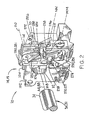
- Figs. 1 and 2 illustrate an optical disk handling apparatus 10 which may be used for producing controlled linear and rotational displacement of an optical disk cartridge 12 which is received in the apparatus.
- the optical disk cartridge 12 may be of the type containing an optical disk which has information encoded on both surfaces thereof.
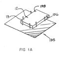
- the cartridge 12 may thus have a generally rectangular top surface 11, Fig. 1, and an identically shaped bottom surface 13, Fig. 1A, which are each adapted to be positioned adjacent to a reading head (not shown) for reading the information contained on the associated disk.
- the apparatus comprises a base means 14, such as block 15, Fig. 2, for supporting various components of the apparatus 10.
- a guide means 16 such as sleeve assembly 17, Fig. 1, is provided for guiding the movement of an optical disk holding means 18.
- the guide means has a forward end 20, a rear end 22 and a central longitudinal axis AA extending between the forward end and rear end.
- the guide means 16 is rotatable in a first direction 24 and a second direction 26 about central longitudinal axis AA.
- the optical disk handling apparatus 10 comprises a shaft means 30 for rotatably mounting the guide means 16 on the base means 14, Fig. 2.
- the shaft means which may comprise a cylindrical steel shaft 31, has a forward end 32 fixedly attached to the rear end 22 of the guide means 16, Fig. 6.
- the shaft means has a second end 34, Fig. 2, which is rotatably received in the base means 14.
- the shaft means 30 has a central longitudinal axis BB which extends in coaxial relationship with the central longitudinal axis AA of the guide means 16.
- the guide means 16 is rotatable about the central longitudinal axis AA thereof through the rotation of the shaft means 30 about its central longitudinal axis BB.
- the optical disk handling apparatus 10 includes an optical disk holding means 18, such as sliding assembly 19, for engaging an optical disk cartridge 12 and holding the cartridge in relatively stationary relationship therewith.
- the optical disk holding means 18 is received in the guide means 16 in linearly displaceable, rotationally nondisplaceable relationship therewith.
- the optical disk holding means 18 is linearly dispiaceable in a forward direction 40 and in a rearward direction 42 with respect to the guide means 16.
- the optical disk handling apparatus includes a drive means 50, such as electric motor 51, for providing reversible driving torque to a transmission means 52.
- a drive means 50 such as electric motor 51, for providing reversible driving torque to a transmission means 52.
- a linear displacement means 54 such as worm drive assembly 55, is provided for producing relative linear displacement between the guide means 16 and the holding means 18 in response to torque applied thereto.
- the apparatus 10 includes a transmission means 52, such as gear assembly 53, for transmitting torque from the drive means 50 for producing rotational displacement of the guide means 16 and linear displacement of the holding means 18.
- the transmission means has a first operating mode, Fig. 14, wherein torque applied thereto by the drive means 50 in a first torque direction 56, Fig. 1, is transmitted to the guide means for rotating the guide means 16 and the holding means 18 in the first direction of rotation 24 about the central longitudinal axis AA of the guide means.
- the transmission means 52 has a second operating mode, Fig. 15, wherein torque applied thereto by the drive means 50 in a second torque direction 58, Fig. 1, is transmitted to the linear displacement means 54 for producing forward 40 linear displacement of the holding means 18 relative the guide means 16.
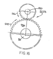
- the transmission means 52 has a third operating mode, Fig. 16, wherein torque applied thereto by the drive means in the first torque direction 56 is transmitted to the linear displacement means 54 for producing rearward 42 linear displacement of the holding means 18 relative the guide means 16.
- Projection means 68 Figs. 1 and 3, 6 and 7, are provided which project rearwardly from the guide means rear end 22 for coacting with a latch means 70.
- the projection means 68 are moved through a circular travel path 72, Figs. 8-10, by rotation of the guide means 16.
- the apparatus 10 comprises plunger means 76, Figs. 6 and 7, which are operatively associated with the optical disk holding means 18 and which are projectable relative the rear end 22 of the guide means 16 for coacting with the latch means 70.
- Plunger means 76 are located in a rearwardmost extended position and move along a circular travel path 77, Figs. 8-10, during rotation of the guide means 16.
- the plunger means 76 have a rearwardly extended position, Fig. 6, and a forwardly retracted position, Fig. 7.
- the apparatus comprises a latch means 70, Fig. 2, mounted on the base means 14 for engaging the projection means 68 during rotation of the guide means 16 in the first direction of rotation 24 for terminating rotation of the guide means and for restraining the guide means from further rotation in the first direction 24 and the second direction 26, Figs. 8-10.
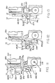
- the latch means 70 also is adapted to coact with the plunger means 76 for disengaging the projection means 72 from the latch means 70, Fig. 13, for enabling rotation of the guide means 16 in the first direction of rotation 24.
- the apparatus 10 also includes restraining means 78 operatively associated with the holding means 18 for restraining linear displacement of the holding means 18 relative to the guide means 16.
- the optical disk handling apparatus 10 may also comprise displacement-sensitive control means 80 for terminating driving torque and for reversing the direction of driving torque provided by the drive means 50 in response to the drive means completing a predetermined angular displacement associated with a predetermined amount of angular displacement of the guide means and/or linear displacement of the holding means.
- This predetermined displacement which causes termination and reversal of the direction of driving torque, may be programmed to coincide with the engagement of the projection means 68 with the latch means 70 and also with the engagement of the holding means 18 with the restraining means 78.
- optical disk handling apparatus 10 in general, various features thereof will now be more fully described.
- base means 14 may comprise a block structure 15 having a forward portion 102 and rear portion 104 and having a central longitudinal bore 106 extending therethrough.
- the central bore 106 may be adapted to accept a bearing assembly 108 therein for enabling rotatable mounting of shaft means 30 within bore 106.
- Bearing assembly 108 may be a conventional ball bearing assembly having an outer portion (not shown) which is adapted to engage the surface of central bore 106 in tight-fitting, non-movable relationship therewith.
- the bearing assembly has an inner portion 112 which is rotatably movable with respect to the outer portion.
- the inner portion is adapted to tightly engage the outer surface of the end portion 32 of shaft 30 and hold it in radially and circumferentially non-movable relationship therewith such that the shaft 30 is freely rotatable relative the block 15.
- the base means 14 may also comprise a bracket assembly 114 which is mounted on the forward portion 102 of block 15 and which is adapted to support various components of the latch means 70 as described in further detail hereinafter.
- Guide means 16 is adapted for receiving a cartridge holding means 18 therein and for limiting the direction of movement of the holding means to a forward direction 40 and a rearward direction 42.
- the guide means in one preferred embodiment, comprises a sleeve assembly 17 which is constructed from a yoke member 120, a lower, generally U-shaped channel member 122, and an upper, generally U-shaped channel member 124 which in one preferred embodiment is identical to member 122.
- the yoke member 120 is an elongate generally radially extending member having a radially extending central body portion 126 and a two radially outwardly and forwardly projecting arm portions 128, 130 which are integrally formed with the central body portion 126.
- the yoke member has a generally flat top surface 132, Fig. 5, and a generally flat bottom surface 134, Fig. 3.
- the yoke central body portion has a centrally located circular bore 136 extending between a planar forward wall portion 138 and a planar rear wall portion 140 thereof, Figs. 3 and 7.
- Circular bore 136 has a central longitudinal axis CC which is adapted to be positioned coaxially with shaft axis BB.
- Bore 136 is adapted to receive a forward end portion 32 of shaft 30 in fixed relationship therewithin, i.e., shaft 30 is not rotatable within bore 136.
- the yoke central body portion 126 has a pair of radially outwardly positioned bores 142, 144 extending axially therethrough, Figs. 5 and 7.
- the axial dimension of each bore may be, e.g., 0.3 inches.
- these bores each have identical square cross-sectional configurations which may be, e.g., 0.3 inches on each side.
- the bores 142, 144 are positioned in diametrically opposite relationship with one another and are each located at the same radial distance, e.g. 1.7 inches, from the center line of bore 136. Bores 142, 144 are adapted to enable plunger means 76 to move axially therethrough as discussed in further detail below.
- the yoke central body portion has a worm drive mounting stud 146 integrally formed therewith and projecting upwardly from the upper surface 132 thereof.
- the worm drive mounting stud has a circular bore 148 extending therethrough which has a central longitudinal axis GG positioned parallel to the central body circular bore axis CC.
- Axis CC may be both vertically and laterally displaced from axis CC, e.g. vertically displaced 0.7 inches and axially displaced 0.2 inches.
- Projection means 68 are fixedly mounted at opposite ends of the yoke central body portion 126 and project axially rearwardly therefrom.
- the projection means 16 include a first projection member 150 positioned near bore 142 and a second projection member 152 positioned near bore 144, Figs. 1 and 3-7.
- the projection members 150, 152 are positioned diametrically oppositely relative central bore axis CC with projection member 150 being positioned below bore 142 and projection member 152 positioned above bore 144.
- Each projection member 150, 152 extends axially rearwardly the same distance, e.g. 0.4 inches, from the rear surface of the yoke upon which it is mounted.
- Each of the axially extending members 150, 152 may terminate in a flat radially extending surface 154, Fig. 6.
- Each projection member 150, 152 comprises an axially and transversely extending, planar, tapering surface 156, Figs. 6, 8 and 11, which is adapted to make initial contact with the latch means 70 during rotation of the guide means in rotation direction 24.
- Each projection member 150, 152 also has a rounded surface 158 which is adapted to be engaged by the latch means 70 to prevent rotation of the guide means in direction 26.
- the projection members 150, 152 are fixedly attached to the yoke member and may be integrally formed therewith.
- the projection members aro equally radially displaced, e.g., 2.0 inches from the central longitudinal axis AA of the guide means, and are adapted to make contact with predetermined portions of the latch means as described in further detail below.
- lower U-shaped channel member 122 is fixedly attached at a rear portion 160 thereof to the flat bottom surface 134, Fig. 3, of the yoke member 120 by conventional attachment means such as attachment screws (not shown).
- the lower channel member 122 may comprise a generally flat longitudinally and laterally extending main body portion 162 and upwardly projecting side wall portions 164, 166.
- a detent means 165 such as an upwardly biased, downwardly deflectable spring metal member 167 having an upwardly projecting rounded portion 169 is mounted above a recessed portion on the upper surface of the main body portion.
- the rounded portion 169 is adapted to engage a hole (not shown) in a bottom surface of the holding means to provide a detent force which resist forward movement of the holding means from its rearwardmost location, as described in further detail below.
- Upper U-shaped channel 124 comprises a rear end portion (not shown) which is fixedly attached to the upper surface portion of the yoke member 120.
- the upper channel portion 164 comprises a flat main body portion 170 which is adapted to be positioned immediately above the lower channel main body portion 162.
- the lower channel member 124 also comprises downwardly extending side wall portions 172, 174 which are adapted to be secured at a bottom edge portion thereof to a top edge portion of lower member side wall portion 164, 166, respectively.
- the upper and lower channel members 122, 124 define a longitudinally extending cavity 178 having a rectangular cross-section which conforms generally to the rectangular cross-sectional shape of an optical disk cartridge 12.
- the cavity extends from the forward wall portion 138 of the yoke member to a rear rectangular opening defined by the forward edges 180, 182 of the upper and lower channel members.
- the distance between yoke forward surface 134 and the forward edge surfaces 180, 182 of the channel members is approximately 0.25 inches greater than the combined axial length of the optical disk holding means 18 and the optical disk 12.
- the upper U-shaped channel 124 has a worm drive mounting projection 184 fixedly attached thereto and projecting upwardly from the top surface portion 186 thereof.
- the worm drive's support block 184 has a bore 185 extending therethrough having a central longitudinal axis HH which is coaxial with axis GG extending through the worm drive mounting stud 146.
- the upper channel main body portion 170 has a longitudinally extending opening 188 therein which enables longitudinal displacement of a worm drive slide member 222 as discussed in further detail below.
- the optical disk holding means 18 may comprise a generally transversely extending central body portion 190 and a pair of pivotally movable finger portions 192, 194 which are mounted at the terminal ends of the central body portion 190.
- the finger portions are adapted to be moved into and out of engagement with notch portions 196, 198 of optical disk cartridge 12.
- the optical disk cartridge is held in fixed relationship with respect to the holding means 18 such that linear movement of the holding means 18 will be accompanied by a corresponding linear movement of the optical disk cartridge 12.
- the finger portions 192, 194 are disengaged from notch portions 196, 198, the optical disk cartridge is released from the holding means.
- the holding means is adapted to move forwardly and rearwardly within the guide means cavity 178.
- the holding means may move to a forwardmost position, indicated by the position of member 222 shown in phantom in Fig. 1, whereat the finger portions 192, 194 thereof project outwardly from the forward opening of the cavity (not shown) to enable the holding means to engage the rear end portion of a cartridge which is positioned next adjacent to the guide means 16 forward end portion.
- the cartridge 12 which is to be engaged may be located in a storage device 195, such as shown schematically in Fig. 1A, which restrains forward and lateral displacement of the cartridge.
- the holding means may move rearwardly in direction 42 to the position illustrated in Fig. 1 whereat the rear wall surface 198 of the holding means, Fig. 7, in one embodiment is positioned in abutting contact with the yoke member forward wall portion 138.
- the holding means may comprise a detent engaging hole (not shown) on a lower surface portion thereof which is adapted to releasably engage guide means detent means 165 as further described below.
- the optical disk holding means 18 has plunger means 76 mounted thereon comprising a first plunger member 210 which may be, e.g., 0.52 inches in length, and a second plunger member 212 of identical axial length.
- the plunger members 210, 212 are fixedly attached to the rear wall surface 198 of the optical disk holding means and are adapted to pass through rectangular bores 142, 144, respectively, in the guide means yoke member 120.
- the plunger members 210, 212 project rearwardly from the rear surface of the yoke member.
- the plunger members 210, 212 project 0.19 inches rearwardly from the rear face surface of the yoke member which circumscribes an associated bore 142 or 144.
- the plunger members each comprise an axial end surface 213, Figs. 6 and 12, which is adapted to axially engage a portion of the latch means so as to trip the latch means to cause disengagement of the projection means as described in further detail hereinafter.
- Each plunger member 210, 212 also comprises an axially extending surface 216, Figs. 12 and 13, which is adapted to engage an axially extending surface of the latch means to produce nontripping, yielding deflection of a portion of the latch means during a period of initial engagement of the latch means and the projection means as described in further detail below.
- Drive means 50 may comprise a conventional, reversible polarity electrical motor 51 such as, for example, that sold under the model designation Series 14000 DC Servo Motor manufactured by Pittman Corporation of Harleysville, Pennsylvania, 19438-0003.
- the drive motor is preferably mounted on a non-movable support surface 216 as by bolts or other conventional attachment means.
- the drive means comprises a rotatable drive shaft 218 which provides the torque used to both flip and to linearly displace the optical disk cartridge 12 engaged by the holding means.
- the displacement-sensitive control means 80 may comprise a conventional motor rotation sensing device, referred to in the art, such as that sold under the product designation HEDS-5500 Encoder which is manufactured by Hewlett-Packard Company having a business address of 3003 Scott Blvd., Santa Clara, California, 95054.
- the drive means 50 electrical motor produces a predetermined number of encoder pulses per revolution, e.g. 2000 pulses per revolution.
- the number of motor revolutions required to produce a predetermined amount of rotation displacement, e.g. 180 o of displacement of the guide means are determined experimentally.
- the number of encoder pulses required to produce this predetermined amount of guide means rotation are thus calculated and used by control software in a microcomputer 219 to determine when the motor operation is to be terminated and reversed.
- the number of motor rotations associated with a predetermined amount of linear displacement of the holding means is also determined experimentally. From this motor revolution value a corresponding encoder displacement value is calculated which is also used by the control software to terminate and reverse motor operation.
- the control means 80 sends an appropriate control signal to a conventional motor switching assembly 81 which terminates operation of the motor and also reverses polarity of the motor such that when the motor is restarted, it will rotate in the direction opposite to that in which it was previously rotating.
- Another signal may be provided to switching assembly 81 to start operation of the motor in the new direction.
- Such a signal may be provided by a human operator or may be provided by an automatic control unit 219 which may comprise a microcomputer and which may be part of a large, integrated optical disk handling system.
- the linear displacement means 54 for producing relative linear displacement between the guide means 16 and the holding means 18 may comprise a worm drive screw 220 having a rear end portion 221 rotatably mounted in mounting stud 146 and a forward end portion 223 rotatably mounted in support block 184.
- a screwingly driven member 222 is threadably mounted on the worm drive screw 220 and is relatively forvardly movable therealong through rotation of screw 220 in a first screw rotation direction 224 and is rearwardly movable therealong through rotation of the screw 220 in a second rotation direction 226.
- the screwingly driven member 222 is fixedly attached to an upper portion of the optical disk holding means 18.
- the optical disk holding means is linearly forwardly displaceable within the guide means through rotation of worm drive screw 220 in first screw direction 224 and is linearly rearwardly displaceable within the guide means through rotation of screw 220 in second screw direction 226.
- the restraining means 78 which restrain the linear displacement of the holding means 18 may comprise the mounting stud 146 and the mounting block 184 which limits the linear displacement of the screwingly driven member 222.
- the worm drive unit may be constructed and arranged such that the holding means comes into contact with the front wall surface 138 of the yoke member prior to contact of the driven member 222 with stud member 146 in which case surface 138 may act as a restraining means 78.
- the construction and arrangement of a storage system such as 195 from which an optical disk cartridge 12 is to be retrieved may be such that the holding means 16 will be retrained in its forward movement by engagement with the optical disk cartridge 12 before screwingly driven member 222 comes into contact with block 184 in which case the optical disk and its storage medium will act as a linear movement restraining means 78.
- the transmission means 52 comprises a first shaft gear member 230 which is received on shaft 30 in coaxial relationship with axis AA thereof and which is freely rotatable with respect to shaft 30.
- the first shaft gear member 230 is drivingly linked as by drive belt 232 and motor gear 234 to the drive shaft 218 of the drive means.
- the transmission means includes a second shaft gear 236 which is freely rotatably received on shaft 30 in coaxial relationship therewith and which is connected to first shaft gear member 230 as by weldament, or other conventional attachment means, such that rotation of first shaft gear member 230 produces corresponding rotation of second shaft gear member 236.
- Second shaft gear member 236 may be a toothed gear member.
- the transmission means also includes a worm drive gear member 238 which is fixedly mounted on an end portion of worm drive screw 220 such that rotation of gear member 236 produces opposite rotation of gear member 238 and worm screw 220.
- Worm drive gear member 238 may also be a toothed gear member.
- the gear ratio between gears 236 and 238 may be 32 to 15.
- Second shaft gear member 236 and worm drive gear member 238 are constructed and arranged such that the two gear members are continuously engaged with one another. As illustrated in Fig.
- first shaft gear member 230 by the drive belt produces corresponding rotation of second shaft gear member 236 in rotation direction 240 which causes worm drive gear member 238 to be orbitally displaced about shaft axes AA, BB in orbital direction 242.
- the orbital motion of the worm drive gear member 238 causes corresponding rotation of the guide means 16 and shaft 30 about their central longitudinal axes AA, BB in direction 24.
- second shaft gear member 236 rotates in direction 242 causing worm drive gear member 238 to rotate about its central longitudinal axis in rotation direction 226 with corresponding rotation of worm drive screw 220 which causes the holding means to be moved rearwardly.
- latch means 70 comprise a first deflectable member means 250.
- Member means 250 is adapted for engaging the projection means 68 during rotation of the guide means 16 in a first direction 24 for terminating the rotation in the first direction 24 and for restraining further rotation of the guide means in the first rotation direction 24.
- the first deflectable member means 250 comprises a first surface portion 252 which is adapted to engage the projection means 68.
- the first deflectable member means has a first operating position as shown in Figs. 2 and 8-12 wherein the first surface portion is positioned in intersecting relationship with the circular travel path 72 of the projection means 68. As illustrated in Fig.
- the first deflectable member means has a second operating position wherein the first surface portion 252 is positioned in displaced relationship with the projection means circular travel path 72.
- the first deflectable member means is biased in the first operating position, Fig. 12, and is deflectable into the second operating position, Fig. 13, through application of axial force thereto by the plunger means 76.
- the first deflectable member means 250 may comprise a pivotal member 251 having a laterally extending pivot axis MM.
- the pivotal member 251 may be biased in the first operating position illustrated in Fig. 2 by a conventional biasing spring 254, Fig. 8.
- the member may include a laterally projecting stud portion 256 which limits its forward displacement through engagement with bracket portion 258.
- the latch means 70 comprises a force transmission member means 270, such as pivotal member 271, for transmitting force from the plunger means to the first deflectable member means 250 for moving the first deflectable member means from the first operating position thereof to the second operating position thereof.
- Force transmission member means 270 comprises a first end 272 attached to the first deflectable member means and a second end 274 having a first surface portion 276 adapted to engage the plunger means 76 during circular movement thereof and a second surface portion 278 adapted to engage the plunger means during axial movement thereof.
- the force transmission member 270 has a first operating position with respect to the first deflectable member means 250 as best illustrated in Figs. 2, 8, 11 and 13.
- the force transmission member means 270 is normally biased in this first operating position.
- the force transmission member means 270 has a second operating position wherein it is relatively downwardly deflected with respect to the first operating position as illustrated in Figs. 10 and 12.
- the plunger means 76 are always positioned in its rearwardmost location as illustrated in Fig. 6. In this position, the circular path 77 which the projection means travel during rotation of the guide means, intersects the first surface portion 276 of the force transmission member means 270 when the first deflectable member means 250 is in its normal biased position, and when the force transmission member means 270 is in its first operating position as illustrated in Figs. 2 and 11.
- the plunger means thus engages the first surface portion 276 of the transmission member means 270 moving it from its first operating position shown in Figs. 2 and 11 to its second operating position illustrated in Figs. 10 and 12. Due to the fact that the projection means exerts little axial force against the force transmission member 270 during the above-described motion, the force transmission member exerts negligible axial force against the first deflectable member means 250 and thus, the first deflectable member means 250 remains in its normal biased position as illustrated in Fig. 12. Relative forward motion of the plunger means from the position illustrated in Fig. 12 causes removal of the downward force applied to the force transmission member means thereby enabling the force transmission member means to return to its first operating position illustrated in phantom in Fig. 12.
- the force transmission member means 270 after its return to its first operating position, has the second surface portion 278 thereof, positioned in aligned relationship with the plunger means such that when the plunger means again moves rearwardly 277, as shown in Fig. 13, it engages the second surface 278 and urges the force transmission member means 270 rearwardly with corresponding rearward deflection 279 of the first deflectable member means 250.
- the force transmission member means may be pivotally attached to the first deflectable member means 250 about a pivot axis NN extending transversely of the plunger means.
- the latch means 70 comprises a second deflectable member means 280 for engaging the projection means 68 during engagement of the projection means by the first deflectable member means 250 for restraining rotation of the guide means 16 in the second rotation direction 26.
- the second deflectable member means 280 has a first surface portion 282, Fig. 2, which is adapted to yieldingly engage the projection means 68 first surface 156 prior to engagement of the projection means with the first deflectable member means 250.
- the second deflectable member means has a second surface portion 284 which is adapted to nonyieldingly engage the projection means 68 second surface 158 during engagement of the projection means with the first deflectable member means 250.
- the second deflectable member means has a first operating position wherein the first surface portion 282 and the second surface portion 284 are both intersected by the circular travel path 72 of the projection means 68 as illustrated in Fig. 8.
- the second deflectable member means has a second operating position, Fig. 9, wherein the first surface portion 282 and the second surface portion 284 are displaced from the circular travel path of the projection means enabling it to pass.
- the second deflectable member has a third operating position, Fig. 10, intermediate the first operating position and the second operating position, wherein the second surface portion 284 is positioned in engaged relationship with the projection means and wherein the projection means is positioned in engaged relationship with the first deflectable member means 250.
- the second deflectable member means 280 is biased in the first operating position and is deflectable from the first operating position to the second operating position, as indicated at 290, through force applied to the first surface portion by the projection means 68.
- the second deflectable member means 280 is biasingly returnable, as indicated at 292, from the second operating position, Fig. 9, to the third operating position, Fig. 10, during the period of engagement between the projection means 68 and the first deflectable member means 250 and is biasingly returnable from the third operating position, Fig. 10, to the first operating position, Fig. 8, subsequent to the disengagement of the projection means 68 from the first deflectable member means 250.
- the second deflectable member means second surface portion 284 may comprise a radially tapering surface which is adapted to progressively, wedgingly engage the projection means during movement of the second deflectable member means from the second operating position thereof to the third operating position thereof.
- This progressive wedging engagement of the projection means by the radially tapering second surface portion 284 of the second deflectable member means 280 causes the projection means to be locked in a zero tolerance relationship between the first deflectable member means and the second deflectable member means when the second deflectable member means is in the third operating position.
- the second deflectable member means may comprise a pivotal member 281 having a pivot axis OO extending parallel to the central axis of rotation AA of the guide means 16.
- the second deflectable member means may be biased in direction 292 as by a conventional torsion spring (not shown) and may be restrained from movement in its biased direction beyond its biased position as by a projection 286 of the pivot member which engages a projecting portion 288 of bracket 114, Fig. 2.
- surface 284 is positioned at a radial distance from axis OO of 0.55 inches at point 285, and 0.59 inches at point 287, tapering uniformly therebetween, Fig. 8.
- FIG. 3-5 The basic sequence of operation of the optical disc handling apparatus 10 is illustrated in Figs. 3-5. Certain structural features of the apparatus have been removed to more clearly illustrate the operation of the apparatus. Thus, with respect to the guide means 16, only the yoke member 120 is shown.
- Fig. 3 illustrates a position occupied by the guide means 16 during rotation thereof in direction 24 between the position occupied in Fig. 4, phantom position, and the position occupied in Fig. 4.
- the holding means 18 is eliminated from this drawing in order to show certain structural details of the yoke member, it will be understood that the holding means is located in its rearwardmost relationship with the guide means, i.e., the position illustrated in Fig. 6, when the guide means 16 is in the relatively rotated position illustrated in Fig. 3.
- the guide means 16 is moved into a latched, non-rotating position through engagement of the second projection member 152 with the latch means 70.
- the holding means is linearly displaced forwardly, i.e., in direction 40, with respect to the guide means. Movement in direction 40 may continue until the holding means encounters a resistance, e.g., the resistance between worm drive linear displaceable member 222 and block 184, Fig. 1-phantom, or the engagement of the optical disc with a storage unit forward housing portion (not shown).
- the optical disc holding means 18 moves rearwardly, direction 42, with respect to the guide means until it reaches its rearmost location relative thereto as illustrated in Fig. 6.
- the second plunger member 212 actuates the latch means 70 to release the second projection member 152 therefrom.
- the holding means 18 reaches its farthest rearward location with respect to the guide means.
- the guide means 16 in response to the release of projection member 152 from the latch means, begins to again rotate in direction 24.
- the rotation of the guide means 16 is terminated when the first projection member 150 is engaged by the latch means 70.
- the holding means is again moved linearly forwardly relative to the guide means and stops movement.
- the holding means then again moves linearly rearwardly with respect to the guide means until reaching its rearwardmost location.
- the first plunger member 210 actuates the latch means 70 to disengage the first projection member 150 therefrom.
- the disengagement of member 150 enables the guide means to again rotate from the position illustrated in Fig. 4-phantom, through the position illustrated in Fig. 3 to the position illustrated in Fig. 4.
- the projection means 68 comprise two diametrically opposed projection members 150, 152 which each travel in the same circular travel path 72 and which each project rearwardly from the guide means 16 the same axial distance.
- the path 72 which each of the projection members 150, 152 travels during rotation of the guide means 16 intersects the top surface portion 252 of the first deflectable member means 250 when the first deflect able member means 250 is in its normally biased position, i.e., the position illustrated in Figs. 2, 8 and 11, in which the top portion thereof projects forwardly from the mounting bracket 114.
- one of the projection members, e.g., 152 is moved into engagement with surface 252.
- the plunger means 76 i.e. plunger members 210 and 212, always occupy a rearwardlymost projected position, e.g., the position illustrated in Fig. 6, during the rotation of guide means 16.
- the second plunger member 212 travels along a concentric path 77 which is positioned slightly radially inwardly, e.g., 0.2 inches inwardly, of path 72 which is travelled by the projection member 152.
- the plunger means rotation path 77 intersects the top surface 276 of force-transmission member means 270.
- force-transmission member means 270 is deflectable from its normal biased position, illustrated in Figs.
- Fig. 11 is a side elevation view showing the relationship of the projection member 152 and the plunger member 212 at the positions thereof illustrated in Fig. 8, just prior to contact with the latch means.
- Figs. 10 and 12 show the deflection of the force-transmission member means 76 produced by downward pressure from the plunger member 212 after the initial engagement between the projection member 152 and first deflectable member means 250.
- the associated plunger member 212 is moved axially forwardly, e.g., Fig. 7, causing it to be removed from engagement with the force-transmission member means 270 and thereby allowing force-transmission member means 270 to return to its normal biased position illustrated in Fig. 11.
- the axial end surface 214 thereof is positioned in axial alignment with the axial end surface 278 of the force-transmission member means 270. The rearward movement of plunger member 212 thus causes engagement between surfaces 214 and 278.
- the force-transmission member means 270 is constructed and arranged such that the axial force transmitted to surface 278 by the plunger member is normal to pivot axis NN and thus does not cause relative deflection of the force-transmission member means 270 relative to the first deflectable member means 250, but rather causes the axial force to be transmitted directly to the second deflectable member means.
- This force causes the second deflectable member means to be moved rearwardly from the position illustrated in Fig. 11 to the position illustrated in Fig. 13.
- the rear ward movement of the second deflectable member means 250 causes surface 252 thereof to be moved axially rearwardly and out of path 72 of projection member 152.
- This release of projection member 152 enables rotation of the guide means in rotation direction 24 with the accompanying movement of projection member 152 along path 72.
- the construction and arrangement of the transmission means 52 is such that torque from the drive means 50 may be provided either to produce rotation of the guide means 16 as illustrated in Fig. 14 or to produce rotation of the worm drive screw 220 in direction 224, Fig. 15, to cause forward movement of the holding means 18 within the guide means 20 or to produce rotation of the worm drive screw 220 in direction 226 to cause rearward movement of the optical disc holding means 18 within the guide means 16.
- the physical events which determine the mode of operation of the transmission means are the engagement and disengagement of the projection means 16 with the latch means 70 and the engagement of the optical disc holding means 18 with a restraining means 78.
- control means 80 senses a motor rotational displacement associated with either the engagement of the projection means with the latch means or the encountering of a restraining means by the linearly moving holding means 18, drive motor operation is terminated and the direction of operation is reversed such that when the motor is re-started, it will transmit torque in the opposite direction.
- the motor is re-started by a signal provided to switching unit 81 through a computer control unit 219. In another embodiment the motor is restarted by a human operator.
- this orbital movement of gear 236 in direction 242 produces rotation of the guide means 16 which is physically connected to gear 236 by the worm drive mounting assembly.
- the guide means 16 rotates in direction 24 until the projection member 152 engages the latch means 70 and is locked into immobile relationship therewith, Figs. 4, 10 and 12.
- the motor rotational displacement associated with this engagement is sensed by the control means 80 which terminates operation of drive motor 50 and reverses the direction of drive motor 50.
- drive motor 50 is restarted and transmits torque in direction 58, Fig. 1. Due to the fact that the second projection member 152 is locked in engagement with the latch means 70, rotation of the guide means 16 is prevented.
- Drive torque from gear 236 thus causes rotation of gear 238 about its central longitudinal axis GG in direction 224, as illustrated in Fig. 15, causing the holding means 18 to move forwardly, direction 40, with respect to the guide means 16 as illustrated in Fig. 7.
- this motion of optical disc holding means 18 in direction 40 continues until the optical disc holding means encounters a restraining means which prevents further motion, such as, for example, the engagement of the driven member 222 with forward worm drive support block 184 or the engagement of an optical disc 12 with a storage unit abutment surface 197, Fig. 1A.
- a restraining means which prevents further motion, such as, for example, the engagement of the driven member 222 with forward worm drive support block 184 or the engagement of an optical disc 12 with a storage unit abutment surface 197, Fig. 1A.
- the holding means After the holding means reaches its rearwardmost position, the torque applied by gear 236 again, Fig. 14, causes orbital movement of gear 238 therewith causing corresponding rotation of the guide means 16.
- the guide means thus rotates, as illustrated in Fig. 5, until the first projection member 150 is engaged by the latch means 70 as illustrated in Fig. 4-phantom. Thereafter, the sequence of events described immediately above is repeated, except that projection member 150 is substituted for projection member 152 and plunger member 210 is substituted for plunger member 212.
- the holding means is moved forwardly in direction 40. Next, it is moved rearwardly in direction 42, causing plunger member 210 to trip the latch means and disengage projection 150 and enabling rotation of the guide means in direction 24.
- the guide means rotates through the position illustrated in Fig. 3 to the position illustrated in Fig. 4. Thus, a full operating cycle of the apparatus 10 is completed.
- gear 238 In a relatively low friction system, a problem may be encountered with respect to the orbital motion of gear 238 as described with reference to Fig. 14.
- a drive motor encounters a resistance, such as that produced by the transition from rearward holding means movement to rotating guide means movement, it tends to pulse, i.e. it accelerates rapidly and then decelerates somewhat before reaching its normal operating speed.
- gear 238 may be accelerated to an orbital velocity which is slightly greater than the rotational velocity of gear 236.
- gear 238, if otherwise unrestrained will rotate slowly about its axis GG in direction 224 as it moves orbitally along path 242.
- a detent means 165 as shown in Fig. 7 may be provided which produces a detent engagement between the holding means and guide means when the holding means is in its rearwardmost position.
- This detent engagement produces a detent force which resists forward displacement of the holding means which is sufficiently great to maintain the holding means in its forwardmost position during the transition from holding means linear movement to guide means rotational movement.
- This detent force is sufficiently small, however such that it may be overcome by the torque provided by the drive motor during the period when the projection means is engaged by the latch means.
- the detent means prevents premature tripping of the latch means but does not otherwise effect the operation of the apparatus.
- optical disc handling apparatus 10 is used to linearly displace an optical disc and is also used to flip an optical disc such that first, the top surface 13 and then the bottom surface 15 thereof, is positioned upwardly.
- a similar apparatus may be provided for handling objects other than optical discs and that such an apparatus may be constructed with any desired number of projection means for the purpose of sequentially placing a series of different surfaces of an object in a predetermined registration position.
- a handling system for a cube-shaped object which is adapted to sequentially place each of four lateral side surfaces thereof in an upwardly facing orientation may be provided through the use of four equally circumferentially spaced projection members on a guide means with four corresponding plunger members being provided on a holding means.
- the construction of the latch means and transmission means in such a system may be identical to that disclosed with respect to the illustrated embodiment.
- the operation of such an apparatus would be identical to the operation of the illustrated embodiment except that the sequential engagement of four projection members rather than two projection members would be required to complete an operating cycle.
Landscapes
- Automatic Disk Changers (AREA)
- Holding Or Fastening Of Disk On Rotational Shaft (AREA)
- Moving Of Heads (AREA)
- Moving Of The Head For Recording And Reproducing By Optical Means (AREA)
- Optical Transform (AREA)
Applications Claiming Priority (2)
| Application Number | Priority Date | Filing Date | Title |
|---|---|---|---|
| US07/278,102 US4998232A (en) | 1988-11-30 | 1988-11-30 | Optical disk handling apparatus with flip latch |
| US278102 | 1988-11-30 |
Publications (3)
| Publication Number | Publication Date |
|---|---|
| EP0371707A2 true EP0371707A2 (de) | 1990-06-06 |
| EP0371707A3 EP0371707A3 (de) | 1991-04-10 |
| EP0371707B1 EP0371707B1 (de) | 1995-04-19 |
Family
ID=23063699
Family Applications (1)
| Application Number | Title | Priority Date | Filing Date |
|---|---|---|---|
| EP89312226A Expired - Lifetime EP0371707B1 (de) | 1988-11-30 | 1989-11-24 | Vorrichtung zur Handhabung von optischen Platten mit einem Kippriegel |
Country Status (4)
| Country | Link |
|---|---|
| US (1) | US4998232A (de) |
| EP (1) | EP0371707B1 (de) |
| JP (1) | JP3009902B2 (de) |
| DE (1) | DE68922281T2 (de) |
Cited By (5)
| Publication number | Priority date | Publication date | Assignee | Title |
|---|---|---|---|---|
| EP0500384A3 (en) * | 1991-02-22 | 1993-03-31 | Mitsubishi Denki Kabushiki Kaisha | Disk cartridge transportation apparatus |
| EP0691647A2 (de) | 1989-10-16 | 1996-01-10 | Hewlett-Packard Company | Ein-/Ausgabekommunikation zwischen automatischem Wechsler und Antrieb |
| EP0709169A3 (de) * | 1994-10-31 | 1996-05-22 | Fujitsu Ltd | |
| EP1291864A3 (de) * | 2001-09-10 | 2004-01-07 | Hewlett-Packard Company | Transport von Datenkassetten |
| WO2005083699A1 (en) * | 2004-02-17 | 2005-09-09 | Koninklijke Philips Electronics N.V. | Disk drive having a disk turning mechanism, and method of turning over a disk |
Families Citing this family (52)
| Publication number | Priority date | Publication date | Assignee | Title |
|---|---|---|---|---|
| US5134600A (en) * | 1989-04-06 | 1992-07-28 | Hewlett-Packard Company | Calibration of a cartridge handling device using mechanical sense of touch |
| US5596556A (en) * | 1993-02-18 | 1997-01-21 | Hewlett-Packard Company | Linear displacement and support apparatus for use in a cartridge handling system |
| US5546366A (en) * | 1993-04-16 | 1996-08-13 | International Business Machines Corporation | Cartridge picker assembly and modular library system |
| JPH07111012A (ja) * | 1993-10-08 | 1995-04-25 | Nkk Corp | ディスクファイル装置 |
| JP3589711B2 (ja) * | 1993-10-12 | 2004-11-17 | ヒューレット・パッカード・カンパニー | デュアルカートリッジ係合アセンブリを備えたカートリッジ取り扱いシステム |
| US5450391A (en) * | 1994-01-18 | 1995-09-12 | Sony Electronics Inc. | Cartridge engagement system for optical disk cartridges |
| US5805561A (en) * | 1994-01-18 | 1998-09-08 | Sony Corporation | Cartridge engagement system for optical disk cartridges having a positionable carriage |
| JPH07220359A (ja) * | 1994-01-31 | 1995-08-18 | Sony Corp | ディスクプレーヤ装置 |
| US5588796A (en) * | 1994-04-18 | 1996-12-31 | Atg Cygnet Inc. | Apparatus and method for handling information storage media |
| US5455810A (en) * | 1994-06-03 | 1995-10-03 | Hewlett-Packard Company | Flexible member tensioning apparatus |
| US5940361A (en) * | 1994-06-03 | 1999-08-17 | Hewlett-Packard Company | Cartridge hand off selection mechanism |
| US5544146B1 (en) * | 1994-08-24 | 1998-03-03 | Hewlett Packard Co | Cartridge handling system |
| US5730031A (en) * | 1994-08-24 | 1998-03-24 | Hewlett-Packard Company | Structure guidance and drive assembly for translation of a robotic picker assembly |
| US6034927A (en) * | 1994-10-20 | 2000-03-07 | Sony Corporation | Carriage for optical disk storage and retrieval array |
| US5576911A (en) * | 1994-10-25 | 1996-11-19 | Sony Corporation | Cartridge locking mechanism and interface |
| US5644559A (en) * | 1995-01-04 | 1997-07-01 | Hewlett-Packard Company | Flip latch assembly for media autochanger |
| US5682096A (en) * | 1995-01-05 | 1997-10-28 | Hewlett-Packard Company | Method and apparatus for monitoring operating positions of a media autochanger |
| US5719833A (en) * | 1995-01-11 | 1998-02-17 | Hewlett-Packard Company | Apparatus for securing a cartridge engaging assembly within a cartridge handling system |
| US5680375A (en) * | 1995-01-13 | 1997-10-21 | Hewlett-Packard Company | Media autochanger flipping assembly with brake |
| US5584207A (en) * | 1995-03-20 | 1996-12-17 | Hewlett-Packard Company | Integrated drive system |
| US6330217B1 (en) | 1995-06-16 | 2001-12-11 | Hewlett-Packard Company | Media cartridge insertion apparatus for a media cartridge storage and handling system |
| US5662539A (en) * | 1995-06-16 | 1997-09-02 | Hewlett-Packard Company | Tensioning device for a flexible drive member |
| US6421306B1 (en) * | 1996-04-29 | 2002-07-16 | Hewlett-Packard Company | Single-side engaging picker for data cartridges |
| US5995459A (en) * | 1996-11-05 | 1999-11-30 | International Data Engineering, Inc. | Flipper mechanism for double-sided media |
| US6094321A (en) * | 1996-11-13 | 2000-07-25 | Sony Electronics Inc. | Recording medium assembly transport system with perpendicular engagement piece |
| EP1012839A4 (de) * | 1997-04-30 | 2001-01-10 | Spectra Logic Corp | Datenkassettenbibliothekssystem |
| DE19807419A1 (de) * | 1998-02-21 | 1999-08-26 | Bdt Buero Datentech Gmbh | Vorrichtung zum Wenden von doppelseitigen Informationsträgern in einem Gerät |
| US6160786A (en) * | 1998-03-20 | 2000-12-12 | Hewlett-Packard Company | Cartridge engaging assembly with rack drive thumb actuator system |
| US6104693A (en) * | 1998-03-20 | 2000-08-15 | Hewlett-Packard Company | Mounting system for cartridge plunge mechanism |
| US6643226B1 (en) | 1998-10-27 | 2003-11-04 | Hewlett-Packard Development Company, L.P. | Mail slot data cartridge exchange system for use with a data storage system |
| US6157513A (en) | 1999-01-26 | 2000-12-05 | Hewlett-Packard Company | Thumb referencing and drive system |
| US6813113B1 (en) | 1999-02-25 | 2004-11-02 | Hewlett-Packard Development Company, L.P. | Data cartridge import/export drawer having three-element, two-configuration slide |
| US6266316B1 (en) | 1999-03-01 | 2001-07-24 | Hewlett-Packard Company | Automatic splaying picker finger |
| US6231291B1 (en) | 1999-03-18 | 2001-05-15 | Hewlett-Packard Company | Method and apparatus for exchanging data cartridges in a jukebox data storage system |
| US6377526B1 (en) | 1999-04-01 | 2002-04-23 | Plasmon Ide, Inc. | Erasable WORM optical disk and method of writing thereto multiple times |
| US7027367B1 (en) | 1999-06-22 | 2006-04-11 | Hewlett-Packard Development Company, L.P. | Apparatus for translating a cartridge access device |
| US7451461B1 (en) | 1999-06-22 | 2008-11-11 | Hewlett-Packard Development Company, L.P. | Laterally expandable modular data storage system |
| US6454509B1 (en) | 2000-04-06 | 2002-09-24 | Plasmon Ide, Inc. | Mechanically actuated picker for data storage library |
| US6445532B1 (en) | 2000-06-07 | 2002-09-03 | Plasmon Ide, Inc. | Import/export element with lead screw and ramp for rotation |
| US6532131B1 (en) | 2000-06-07 | 2003-03-11 | Plasmon Ide, Inc. | Import/export element with selector nut and bevel gear for rotation |
| US6560060B1 (en) | 2000-06-07 | 2003-05-06 | Plasmon Ide, Inc. | Import/export element with screw-mounted bevel gear for rotation |
| US6643091B2 (en) | 2001-03-05 | 2003-11-04 | Hewlett-Packard Development Company | Automated data cartridge import/export drawer |
| US7455375B2 (en) * | 2001-08-23 | 2008-11-25 | Hewlett-Packard Development Company, L.P. | Removable media storage method and device for a data storage system |
| US6654318B2 (en) | 2001-08-23 | 2003-11-25 | Hewlett-Packard Development Company, L.P. | Devices for storing data media in a data storage system |
| US6661747B2 (en) | 2001-08-23 | 2003-12-09 | Hewlett-Packard Development Company, L.P. | Systems for retaining data media in a media storage device |
| US6848114B2 (en) * | 2001-08-23 | 2005-01-25 | Hewlett-Packard Development Company, L.P. | Bulk access system for a data storage system |
| US6733223B2 (en) | 2001-08-23 | 2004-05-11 | Hewlett-Packard Development Company, L.P. | Systems and methods for providing a removable media handling system in data storage system |
| US7046587B2 (en) * | 2001-08-23 | 2006-05-16 | Hewlett-Packard Development Company, L.P. | Systems and methods for providing automatic access to data media in a data storage system |
| US7019940B2 (en) * | 2001-09-24 | 2006-03-28 | Hewlett-Packard Development Company, L.P. | Universal cartridge magazine system and method |
| US7342849B2 (en) * | 2003-01-31 | 2008-03-11 | Sony Corporation | Recording and/or playback device |
| US7290978B2 (en) * | 2004-06-09 | 2007-11-06 | N&K Technology Inc. | Photomask flipper and single direction inspection device for dual side photomask inspection |
| GB2423625A (en) * | 2005-02-26 | 2006-08-30 | M5 Data Ltd | Library with counter-balanced picker mechanism |
Family Cites Families (8)
| Publication number | Priority date | Publication date | Assignee | Title |
|---|---|---|---|---|
| US3501153A (en) * | 1967-03-01 | 1970-03-17 | Wurlitzer Co | Changer and selector mechanism |
| US4135245A (en) * | 1977-01-04 | 1979-01-16 | Hewlett-Packard Company | Plotter with automatic pen-changer |
| US4417258A (en) * | 1982-01-13 | 1983-11-22 | Hewlett-Packard Company | Bi-directional pen changer |
| US4573129A (en) * | 1982-02-25 | 1986-02-25 | Hewlett-Packard Company | Automatic pen-sensor |
| US4608679A (en) * | 1984-07-11 | 1986-08-26 | Filenet Corporation | Optical storage and retrieval device |
| US4786995A (en) * | 1986-11-06 | 1988-11-22 | Peripheral Technology, Inc | Automatic head retract system for disk drive |
| US4787074A (en) * | 1987-02-27 | 1988-11-22 | Eastman Kodak Company | Automated library for data storage disks |
| US4817071A (en) * | 1988-04-22 | 1989-03-28 | Eastman Kodak Company | Disk-loading station for automated disk library |
-
1988
- 1988-11-30 US US07/278,102 patent/US4998232A/en not_active Expired - Lifetime
-
1989
- 1989-11-24 DE DE68922281T patent/DE68922281T2/de not_active Expired - Fee Related
- 1989-11-24 EP EP89312226A patent/EP0371707B1/de not_active Expired - Lifetime
- 1989-11-30 JP JP1312215A patent/JP3009902B2/ja not_active Expired - Fee Related
Cited By (7)
| Publication number | Priority date | Publication date | Assignee | Title |
|---|---|---|---|---|
| EP0691647A2 (de) | 1989-10-16 | 1996-01-10 | Hewlett-Packard Company | Ein-/Ausgabekommunikation zwischen automatischem Wechsler und Antrieb |
| EP0500384A3 (en) * | 1991-02-22 | 1993-03-31 | Mitsubishi Denki Kabushiki Kaisha | Disk cartridge transportation apparatus |
| EP0709169A3 (de) * | 1994-10-31 | 1996-05-22 | Fujitsu Ltd | |
| US5781517A (en) * | 1994-10-31 | 1998-07-14 | Fujitsu Limited | Accessor hand mechanism having grooves for opening and closing fingers |
| US6141178A (en) * | 1994-10-31 | 2000-10-31 | Fujitsu Limited | Accessor hand mechanism having grooves for opening and closing fingers |
| EP1291864A3 (de) * | 2001-09-10 | 2004-01-07 | Hewlett-Packard Company | Transport von Datenkassetten |
| WO2005083699A1 (en) * | 2004-02-17 | 2005-09-09 | Koninklijke Philips Electronics N.V. | Disk drive having a disk turning mechanism, and method of turning over a disk |
Also Published As
| Publication number | Publication date |
|---|---|
| JP3009902B2 (ja) | 2000-02-14 |
| US4998232A (en) | 1991-03-05 |
| DE68922281T2 (de) | 1995-08-24 |
| JPH02192064A (ja) | 1990-07-27 |
| DE68922281D1 (de) | 1995-05-24 |
| EP0371707B1 (de) | 1995-04-19 |
| EP0371707A3 (de) | 1991-04-10 |
Similar Documents
| Publication | Publication Date | Title |
|---|---|---|
| US4998232A (en) | Optical disk handling apparatus with flip latch | |
| EP0384622B1 (de) | Kassettenhandhabungssystem | |
| US5043962A (en) | Cartridge handling system | |
| US5101387A (en) | Lateral displacement control assembly for an optical disk handling system | |
| JP3578653B2 (ja) | カートリジ係合アセンブリ | |
| US5184336A (en) | Mechanical assembly for alternately producing displacement of a carriage and rotation of a carriage mounted gear | |
| US4736356A (en) | Optical disk drive | |
| EP0834382A2 (de) | Speicherbibliothek für Kassetten welche ein Aufzeichnungsmedium enthalten | |
| US5682096A (en) | Method and apparatus for monitoring operating positions of a media autochanger | |
| US5563865A (en) | Compact disk transport tray moved by a disk reading mechanism | |
| US5644559A (en) | Flip latch assembly for media autochanger | |
| JP2005063646A (ja) | 記憶装置を取扱うための機械的な把持装置、自動格納ライブラリおよび把持機構で記憶カートリッジを把持するための方法 | |
| JPH11316997A (ja) | カ―トリジ係合アセンブリ | |
| US5680375A (en) | Media autochanger flipping assembly with brake | |
| JP2005063648A (ja) | 記憶装置を搬送するための機械的な把持装置、自動格納ライブラリおよび記憶装置を搬送するための機械的な把持装置を制御するための方法 | |
| US7180702B2 (en) | Data cartridges handler including a ring-shaped carousel and a picker within the inner periphery of the carousel | |
| EP1642291B1 (de) | Abnehmereinheit-homing-mechanismus für eine plattenlaufwerkeinheit | |
| SU1227264A1 (ru) | Устройство дл ориентировани шпилек | |
| JP3406825B2 (ja) | ロ−ディング機構及び磁気テープ装置 | |
| WO1996010253A1 (en) | Transducer positionner system and method for a combined removable random and sequential access media drive |
Legal Events
| Date | Code | Title | Description |
|---|---|---|---|
| PUAI | Public reference made under article 153(3) epc to a published international application that has entered the european phase |
Free format text: ORIGINAL CODE: 0009012 |
|
| AK | Designated contracting states |
Kind code of ref document: A2 Designated state(s): DE FR GB |
|
| PUAL | Search report despatched |
Free format text: ORIGINAL CODE: 0009013 |
|
| RHK1 | Main classification (correction) |
Ipc: G11B 17/04 |
|
| AK | Designated contracting states |
Kind code of ref document: A3 Designated state(s): DE FR GB |
|
| 17P | Request for examination filed |
Effective date: 19910607 |
|
| 17Q | First examination report despatched |
Effective date: 19930616 |
|
| GRAA | (expected) grant |
Free format text: ORIGINAL CODE: 0009210 |
|
| AK | Designated contracting states |
Kind code of ref document: B1 Designated state(s): DE FR GB |
|
| REF | Corresponds to: |
Ref document number: 68922281 Country of ref document: DE Date of ref document: 19950524 |
|
| ET | Fr: translation filed | ||
| PLBE | No opposition filed within time limit |
Free format text: ORIGINAL CODE: 0009261 |
|
| STAA | Information on the status of an ep patent application or granted ep patent |
Free format text: STATUS: NO OPPOSITION FILED WITHIN TIME LIMIT |
|
| 26N | No opposition filed | ||
| REG | Reference to a national code |
Ref country code: GB Ref legal event code: 732E |
|
| REG | Reference to a national code |
Ref country code: FR Ref legal event code: TP |
|
| REG | Reference to a national code |
Ref country code: GB Ref legal event code: IF02 |
|
| PGFP | Annual fee paid to national office [announced via postgrant information from national office to epo] |
Ref country code: GB Payment date: 20070125 Year of fee payment: 18 |
|
| PGFP | Annual fee paid to national office [announced via postgrant information from national office to epo] |
Ref country code: DE Payment date: 20070228 Year of fee payment: 18 |
|
| PGFP | Annual fee paid to national office [announced via postgrant information from national office to epo] |
Ref country code: FR Payment date: 20070207 Year of fee payment: 18 |
|
| GBPC | Gb: european patent ceased through non-payment of renewal fee |
Effective date: 20071124 |
|
| PG25 | Lapsed in a contracting state [announced via postgrant information from national office to epo] |
Ref country code: DE Free format text: LAPSE BECAUSE OF NON-PAYMENT OF DUE FEES Effective date: 20080603 |
|
| REG | Reference to a national code |
Ref country code: FR Ref legal event code: ST Effective date: 20080930 |
|
| PG25 | Lapsed in a contracting state [announced via postgrant information from national office to epo] |
Ref country code: GB Free format text: LAPSE BECAUSE OF NON-PAYMENT OF DUE FEES Effective date: 20071124 |
|
| PG25 | Lapsed in a contracting state [announced via postgrant information from national office to epo] |
Ref country code: FR Free format text: LAPSE BECAUSE OF NON-PAYMENT OF DUE FEES Effective date: 20071130 |