EP0376708A2 - Lichtfeststellungsvorrichtung - Google Patents
Lichtfeststellungsvorrichtung Download PDFInfo
- Publication number
- EP0376708A2 EP0376708A2 EP89313629A EP89313629A EP0376708A2 EP 0376708 A2 EP0376708 A2 EP 0376708A2 EP 89313629 A EP89313629 A EP 89313629A EP 89313629 A EP89313629 A EP 89313629A EP 0376708 A2 EP0376708 A2 EP 0376708A2
- Authority
- EP
- European Patent Office
- Prior art keywords
- light
- reshaping
- axis
- photo
- photo detector
- Prior art date
- Legal status (The legal status is an assumption and is not a legal conclusion. Google has not performed a legal analysis and makes no representation as to the accuracy of the status listed.)
- Withdrawn
Links
Images


Classifications
-
- G—PHYSICS
- G11—INFORMATION STORAGE
- G11B—INFORMATION STORAGE BASED ON RELATIVE MOVEMENT BETWEEN RECORD CARRIER AND TRANSDUCER
- G11B7/00—Recording or reproducing by optical means, e.g. recording using a thermal beam of optical radiation by modifying optical properties or the physical structure, reproducing using an optical beam at lower power by sensing optical properties; Record carriers therefor
- G11B7/08—Disposition or mounting of heads or light sources relatively to record carriers
- G11B7/09—Disposition or mounting of heads or light sources relatively to record carriers with provision for moving the light beam or focus plane for the purpose of maintaining alignment of the light beam relative to the record carrier during transducing operation, e.g. to compensate for surface irregularities of the latter or for track following
-
- G—PHYSICS
- G11—INFORMATION STORAGE
- G11B—INFORMATION STORAGE BASED ON RELATIVE MOVEMENT BETWEEN RECORD CARRIER AND TRANSDUCER
- G11B7/00—Recording or reproducing by optical means, e.g. recording using a thermal beam of optical radiation by modifying optical properties or the physical structure, reproducing using an optical beam at lower power by sensing optical properties; Record carriers therefor
- G11B7/12—Heads, e.g. forming of the optical beam spot or modulation of the optical beam
- G11B7/135—Means for guiding the beam from the source to the record carrier or from the record carrier to the detector
- G11B7/1381—Non-lens elements for altering the properties of the beam, e.g. knife edges, slits, filters or stops
-
- G—PHYSICS
- G11—INFORMATION STORAGE
- G11B—INFORMATION STORAGE BASED ON RELATIVE MOVEMENT BETWEEN RECORD CARRIER AND TRANSDUCER
- G11B7/00—Recording or reproducing by optical means, e.g. recording using a thermal beam of optical radiation by modifying optical properties or the physical structure, reproducing using an optical beam at lower power by sensing optical properties; Record carriers therefor
- G11B7/08—Disposition or mounting of heads or light sources relatively to record carriers
- G11B7/09—Disposition or mounting of heads or light sources relatively to record carriers with provision for moving the light beam or focus plane for the purpose of maintaining alignment of the light beam relative to the record carrier during transducing operation, e.g. to compensate for surface irregularities of the latter or for track following
- G11B7/0908—Disposition or mounting of heads or light sources relatively to record carriers with provision for moving the light beam or focus plane for the purpose of maintaining alignment of the light beam relative to the record carrier during transducing operation, e.g. to compensate for surface irregularities of the latter or for track following for focusing only
- G11B7/0909—Disposition or mounting of heads or light sources relatively to record carriers with provision for moving the light beam or focus plane for the purpose of maintaining alignment of the light beam relative to the record carrier during transducing operation, e.g. to compensate for surface irregularities of the latter or for track following for focusing only by astigmatic methods
-
- G—PHYSICS
- G11—INFORMATION STORAGE
- G11B—INFORMATION STORAGE BASED ON RELATIVE MOVEMENT BETWEEN RECORD CARRIER AND TRANSDUCER
- G11B7/00—Recording or reproducing by optical means, e.g. recording using a thermal beam of optical radiation by modifying optical properties or the physical structure, reproducing using an optical beam at lower power by sensing optical properties; Record carriers therefor
- G11B7/08—Disposition or mounting of heads or light sources relatively to record carriers
- G11B7/09—Disposition or mounting of heads or light sources relatively to record carriers with provision for moving the light beam or focus plane for the purpose of maintaining alignment of the light beam relative to the record carrier during transducing operation, e.g. to compensate for surface irregularities of the latter or for track following
- G11B7/0908—Disposition or mounting of heads or light sources relatively to record carriers with provision for moving the light beam or focus plane for the purpose of maintaining alignment of the light beam relative to the record carrier during transducing operation, e.g. to compensate for surface irregularities of the latter or for track following for focusing only
- G11B7/0916—Foucault or knife-edge methods
-
- G—PHYSICS
- G11—INFORMATION STORAGE
- G11B—INFORMATION STORAGE BASED ON RELATIVE MOVEMENT BETWEEN RECORD CARRIER AND TRANSDUCER
- G11B7/00—Recording or reproducing by optical means, e.g. recording using a thermal beam of optical radiation by modifying optical properties or the physical structure, reproducing using an optical beam at lower power by sensing optical properties; Record carriers therefor
- G11B7/12—Heads, e.g. forming of the optical beam spot or modulation of the optical beam
- G11B7/135—Means for guiding the beam from the source to the record carrier or from the record carrier to the detector
- G11B7/1372—Lenses
- G11B7/1378—Separate aberration correction lenses; Cylindrical lenses to generate astigmatism; Beam expanders
Definitions
- the present invention relates generally to a light detecting apparatus, and more particularly to a light detecting apparatus which can be applied to an optical information reproducing apparatus.
- optical discs have been used in many fields as information recording media.
- the advances in laser oscillator technology have contributed to optical discs having superior high density and high speed characteristics.
- Information is recorded on these discs in the form of a series of pits and the change in reflectivity of light irradiated onto the disc is used in order to read the recorded information.
- a focus servo is required for the control of the irradiated light so that it can be accurately focussed on the optical disc.
- various methods have been devised for detecting focus in order to operate this focus servo.
- the focus servo operates by detecting the focal point using the fluctuation of the position of the light reflected from the optical disc to the photo detector due to the distance between the optical disc and the objective lens.
- the photo detector is located at the image formation point of the light reflected from the optical disc. This photo detector has two photo detecting elements.
- a device in which light from an optical disc is irradiated onto a photo detector, which is divided into four parts, with these parts combined in a square, via a cylindrical lens which generates astigmatism.
- This photo detector performs detection of focussing errors and generates focus error signals and reading information according to the area of light irradiated.
- the photo detector is located at the position of the minimum light spot formed between two focal lines which are formed in the direction of the generatrix generated by the cylindrical lens and the direction orthogonal to that generatrix. Detection of focussing errors signals and reading of information are carried out by the same photo detector.
- the size of the beam spot of light on the light detecting apparatus becomes small because the photo detector is positioned at the image formation point of the light from the optical disc. For this reason, it is liable to be affected by light axis divergency and the like due to deformation of the optical elements through temperature changes and the like. Thus, there is the disadvantage that accurate focussing control cannot be executed.
- the present invention therefore seeks to provide a light detecting apparatus capable of accurate focal point detection without being affected by light axis divergency and the like due to temperature changes and the like.
- a light detecting apparatus includes a potion for receiving light with a predetermined light pattern, a first element for extracting part of the received light in reference to the light pattern, a second element for reshaping the light pattern of the received light and a photo-detecting element on which the received light is projected.
- a light detecting apparatus includes a portion for receiving light with a predetermined light pattern, a first element for reshaping the light pattern of the received light in a first direction, a second element for reshaping the light pattern of the received light in a second direction which is asymmetrical with the first direction and a photo-detecting element on which the received light is projected.
- FIGURE 1A a first embodiment of the light detecting apparatus according to the present invention will be described in detail.
- the light detecting apparatus comprises a light source 10 such as a semiconductor laser, a collimator lens 12 which converts the light from light source 10 into a parallel beam, a beam splitter 14, an objective lens 16 which condenses the light onto an information recording medium such as an optical disc 18, a partial light extracting element such as a light pattern defining mask 20 onto which the light reflected from information recording medium 18 is irradiated, a converging lens 22 for converging the light, a light pattern reshaping element such as a cylindrical lens 24 and a photo detector 26 which detects the light reflected from information recording medium 18.
- a light source 10 such as a semiconductor laser
- a collimator lens 12 which converts the light from light source 10 into a parallel beam
- a beam splitter 14 an objective lens 16 which condenses the light onto an information recording medium such as an optical disc 18, a partial light extracting element such as a light pattern defining mask 20 onto which the light reflected from information recording medium 18 is irradiated, a con
- Information recording medium 18 is a so-called optical disc.
- FIGURE 2 it is composed of substrate 30 and recording film 32 on which information is recorded.
- Substrate 30 is composed of plastic, glass, aluminium, or the like.
- Recording film 32 is composed of a metal film, a semi-metallic film, an inorganic film or an organic film. Recording track 34 is formed beforehand in a raised and indented state on substrate 30 and recording film 32 in concentric circles or in a spiral form.
- Information pits 36 are formed along recording track 34.
- the light irradiated onto optical disc 18 is reflected by optical disc 18 and passes once more towards objective lens 16. After being transmitted through objective lens 16, the light is irradiated onto beam splitter 14.
- the light irradiated onto beam splitter 14 is led toward light pattern defining mask 20 and is transmitted through light pattern defining mask 20 and irradiated onto photo detector 26 via converging lens 22 and cylindrical lens 24.
- the light irradiated onto light pattern defining mask 20 has an uneven light quantity distribution through the influence of interference of the light reflected from the pits on optical disc 18 and the light from their surroundings.
- the light quantity slightly decreases in inner area 38a inside boundary line 38 near light axis 37, but greatly decreases outer area 38b far from light axis 37.
- the inner area 38a is brighter than the outer area 38b.
- the pattern of inner area 38a formed along boundary line 38 is formed symmetrically along the direction of recording track 34 of optical disc 18. Moreover, for the direction orthogonal to that of recording track 34 of optical disc 18, the pattern of inner area 38a is also symmetrical to this boundary line 38.
- Light pattern defining mask 20 has first and second areas 19a and 19b which are arranged in the direction parallel with the generatrix direction23 of cylindrical lens 24 which is described in detail later, as shown in FIGURE 4A.
- First area 19a defines a light transmitting portion 20a and a light masking portions 20c along the direction of first area 19a.
- Second area 19b defines a light transmitting portion 20b and light masking portions 20d which are orthogonal to light transmitting portion 20a and light masking portions 20c of first area 19a.
- light masking portions 20c and 20d are each asymmetric about the a axis and the b axis, and each portion is formed on each of first and second areas 19a and 19b along the a axis.
- Light masking film 21 is provided on light masking portions 20c and 20d.
- Light masking film 21 may comprise, for instance, aluminium film, chrome film, carbon film, or multi layer films formed of such inorganic substances as the oxide or nitride of indium.
- the reflection by light masking film 21 is small, and therefore it is effective from the viewpoint of producing hardly any stray light in the optical system. If light masking film 21 reflects a tolerable amount of light, the reflected light makes undesired pits on optical disc 18. Further the reflected light from light masking film 21 is again routed to photo detector 26 through reflection by optical disc 18 so that the detecting operation of photo detector 26 is disturbed.
- Such objects for preventing undesired pits and the disturbance against the detecting operation of photo detector 26 are also accomplished by inclining the plane of light pattern defining mask 20 to light axis L of the light.
- Light pattern defining mask 20 can be composed as shown in FIGURE 4B. That is, light pattern defining mask 20 has light transmitting portions 20e and 20f which transmit the light irradiated onto light pattern defining mask 20. Light transmitting portions 20e and 20f are provided inside spot 19 of the light irradiated onto light pattern defining mask 20, and they both have approximately the same areas with circular patterns. These light transmitting portions 20e and 20f are formed so that light transmitting portion 20e and light transmitting portion 20f with their circular patterns are symmetrical about light axis L of the light irradiated onto light pattern defining mask 20.
- the light irradiated onto light transmitting portions 20a and 20b (FIGURE 4A) or 20e and 20f (FIGURE 4B) passes through light pattern defining mask 20 and is led to a light condensing element such as a converging lens 22, as shown in FIGURE 1A.
- the light condensing element, e.g., converging lens 22 has the function of evenly condensing the irradiated light on photo detector 26. If the light passing through light pattern defining mask 20 and cylindrical lens 24 is sufficiently condensed a thin beam, the light condensing element, e.g., converging lens 22 can be removed.
- the light which has passed through converging lens 22 is irradiated onto cylindrical lens 24.
- Cylindrical lens 24 generates focal lines on which the light is condensed in the direction of its generatrix 23 and the direction orthogonal to its generatrix 23 respectively, and introduces astigmatism to the light.
- Cylindrical lens 24 is positioned so that generatrix direction 23 is parallel to the a axis.
- the light which has passed through cylindrical lens 24 is condensed in the same direction as before irradiation onto cylindrical lens 24, without being affected by the action of cylindrical lens 24 in the generatrix direction 23, and is condensed at focal point H. However, it is affected by the action of cylindrical lens 24 in the direction orthogonal to the generatrix direction 23 and is condensed at focal point G, which is a shorter distance from generatrix 23.
- Photo detector 26 is composed of four photo detecting cells 26a, 26b, 26c and 26d, and each cell has the same degree of photo detecting property. Photo detecting cells 26a, 26b, 26c and 26d are positioned so that each is in contact with the c axis, which is set parallel to the a axis, and with the d axis, which is set parallel to the b axis, and light detector 26 is a combination of these cells in a square. Since the image on photo detector 26 is positioned at an image formation point corresponding to the image on optical disc 18, it hardly undergoes any diffraction of light.
- FIGURE 4A the method of focussing error detection using light pattern defining mask 20, as shown in FIGURE 4A, will be described with reference to FIGURES 5A, 5B and 5C.
- a photo detecting apparatus which has light pattern defining mask 20, as shown in FIGURE 4A, if the light irradiated from objective lens 16 onto optical disc 18 is in a focussed state, the pattern of beam spot 28 on photo detector 26 is as shown in FIGURE 5A.
- the light from optical disc 18 which has passed through light transmitting portion 20a of light pattern defining mask 20 is irradiated onto photo detecting cells 26a and 26b of photo detector 26.
- the quantities of light irradiated onto photo detecting cells 26a and 26b are approximately equal and also take a pattern which has a certain degree of width in the d axis direction.
- the light which has passed through light transmitting portion 20b is irradiated onto photo detecting cells 26c and 26d of photo detector 26.
- the quantities of light irradiated onto photo detecting cells 26c and 26d are also approximately equal and also take a pattern which has a certain degree of width in the d axis direction.
- the pattern of beam spot 28 becomes as shown in FIGURE 5B. That is to say, in the case of the light which has passed through light transmitting portion 20a of light pattern defining mask 20, the focal point position in the direction orthogonal to generatrix direction 23 is closer to photo detector 26 than focal point position G when focussed.
- the width of beam spot 28 on photo detector 26 becomes narrower in the d axis direction.
- light is irradiated onto photo detecting cell 26a of photo detector 26 in a state in which the width of beam spot 28 has become wider.
- the focal point position in the direction orthogonal to generatrix direction 23 is closer to photo detector 26 than focal point position G when focussed, and the width of beam spot 28 becomes narrower in the d axis direction.
- the light is irradiated onto photo detecting cell 26c of photo detector 26 in a state in which the width of beam spot 28 has become wider.
- the pattern of beam spot 28 becomes as shown in FIGURE 5C.
- the focal point position in the direction orthogonal to generatrix direction 23 is farther from photo detector 26 than focal point position G when focussed. Consequently, the width of beam spot 28 on photo detector 26 becomes wider in the d axis direction.
- the beam spot shifts to the opposite side with regard to the d axis and is irradiated onto photo detecting cell 26b of photo detector 26.
- the focal point position in the direction orthogonal to generatrix direction 23 is farther from photo detector 26 than focal point position G when focussed. Consequently, the width of beam spot 28 on photo detector 26 becomes wider in the d axis direction. Moreover, concerning generatrix direction 23, since the light is irradiated onto photo detector 26 after it has been condensed, as opposed to the case when optical disc 18 was closer, the beam spot shifts to the opposite side with regard to the d axis and is irradiated onto photo detecting cell 26d of photo detector 26.
- FIGURE 48 methods of focussing error detection using the light pattern defining mask 20, as shown in FIGURE 48, will be described with reference to FIGURES 5D, 5E and 5F.
- the patterns of beam spots 28a and 28b on photo detector 26 are as shown in FIGURE 5D. That is to say, when in the focussed state, the light from optical disc 18 which has passed through light transmitting portion 20e of light pattern defining mask 20 is irradiated onto photo detecting cells 26a and 26b of photo detector 26.
- the quantities of light irradiated onto photo detecting cells 26a and 26b are approximately equal and also take the form of approximately oval-patterned beam spot 28a which has a certain degree of width in the d axis direction. Also, in the same way, the light which has passed through light transmitting portion 20f is irradiated onto photo detecting cells 26c and 26d of photo detector 26. The quantities of light irradiated onto photo detecting cells 26c and 26d are approximately equal and also take the form of approximately oval-patterned beam spot 28b which has a certain degree of width in the d axis direction.
- the patterns become as shown in FIGURE 5E. That is to say, in the case of the light which has passed through light transmitting portion 20e of light pattern defining mask 20, the focal point position in the direction orthogonal to generatrix direction 23 is closer to photo detector 26 than focal point position G when focussed. Consequently, the width of beam spot 29a on photo detector 26 becomes narrower in the d axis direction. Moreover, in the c axis direction, light is irradiated onto photo detecting cell 26a of photo detector 26 in a state in which the width of beam spot 29a has become wider.
- the focal point position in the direction orthogonal to generatrix direction 23 is closer to photo detector 26 than focal point position G when focussed, and the width of beam spot 29b becomes narrower in the d axis direction.
- the light is irradiated onto photo detecting cell 26c of photo detector 26 in a state in which the width of beam spot 29b has become wider.
- beam spot 30a shifts to the opposite side with regard to the d axis and is irradiated onto photo detecting cell 26b of photo detector 26.
- the focal point position in the direction orthogonal to generatrix direction 23 is farther from photo detector 26 than focal point position G when focussed. Consequently, the width of beam spot 30b on photo detector 26 becomes wider in the d axis direction. Moreover, in c axis direction 23, since the light is irradiated onto photo detector 26 after it has been condensed, as opposed to the case when optical disc 18 was closer, beam spot 30b shifts to the opposite side with regard to the d axis and is irradiated onto photo detecting cell 26d of photo detector 26.
- the pattern of beam spot 28 irradiated onto photo detector 26 changes depending on the positional relationship between optical disc 18 and objective lens 16.
- a focussing error signal is generated by the detection of this pattern.
- the composition of the signal processing circuit which generates this focussing error signal is shown in FIGURE 6.
- the output signals of photo detecting cells 26a and 26c are added by adder 40, and the output signals of photo detecting cells 26b and 26d are added by adder 42.
- the focussing error signal can be obtained by subtracting the signals obtained by adder 40 and adder 42 using subtractor 50. This focussing error signal is supplied to objective lens drive circuit 56, and, by controlling objective lens drive unit 58, objective lens 16 is shifted in the light axis direction and focussing is executed.
- the position in which (1) the direction along recording track 34 of optical disc 18, (2) generatrix direction 23 of cylindrical lens 24 and (3) the c axis direction of photo detector 26 are in agreement with each other is taken.
- the change in the diffraction distribution of the light reflected from optical disc 18 is used through the relative relationship between the irradiating light irradiated onto optical disc 18 and the direction along recording track 34 to determine a tracking error.
- the light which irradiates onto photo detector 26 is symmetrical about the c axis of photo detector 26. That is to say, equal quantities of light are irradiated onto each of photo detecting cells 26a and 26b, 26c and 26d. As opposed to this, when the beam of irradiated light slips from the centerline of recording track 34, the light which irradiates onto photo detector 26 becomes asymmetrical about the c axis of photo detector 26. That is to say, differing light quantities are irradiated onto photo detecting cells 26a and 26b, 26c and 26d.
- the output signals of respective photo detecting cells 26a and 26b are added by adder 46, and the output signals of photo detecting cells 26c and 26d are added by adder 48.
- the output signals of adders 46 and 48 are output signals corresponding to the light quantities irradiated onto photo detecting cells 26a and 26b and onto photo detecting cells 26c and 26d, respectively.
- a tracking error signal can be obtained which corresponds to the difference in the light quantities irradiated onto photo detecting cells 26a and 26b and onto photo detecting cells 26c and 26d.
- a tracking servo is operated by supplying this tracking error signal to objective lens driving circuit 60 and driving objective lens 16 by controlling driving unit 62.
- tracking error detection can be executed without any error.
- beam spot 28 is irradiated onto photo detector 26 by splitting it diagonally, for instance, onto photo detecting cells 26a and 26c or onto photo detecting cells 26b and 26d. Therefore, direction sensitivity is increased and thus stable focussing detection can be achieved without detection errors.
- beam spots 29a and 29b and 30a and 30b rotate in opposite directions about the center of photo detector 26 to beam spots 28a and 28b. That is to say, taking beam spots 28a and 28b which are irradiated onto photo detector 26 when optical disc 18 and objective lens 16 are in focus as the standard, changes in the positional relationship between optical disc 18 and objective lens 16 can be detected. Also, there is no necessity to secure photo detector 26 at focal point position H on focal line b of the light through cylindrical lens 24. Photo detector 26 may be located before or beyond focal point position H, and photo detector 26 may be rotated so that the positions of beam spots 28a and 28b when in focus are equally divided by the d axis of photo detector 26 when irradiated onto it.
- FIGURE 4A Another construction of light pattern defining mask 20 in FIGURE 4A is described with reference to FIGURES 7 and 8.
- positioning photo detector 26 between focal point position G in the direction orthogonal to generatrix direction 23 and focal point position H in generatrix direction 23 was tried.
- FIGURE 7 in the case of light pattern defining mask 20, light masking film 21 is located as shown.
- the remaining area of the light pattern defining mask 20 are light transmitting.
- the pattern of beam spot 28 on photo detector 26 is asymmetric about the a axis of light pattern defining mask 20 of FIGURE 7, and is formed by the light which is extracted in a rectangular pattern from each of the first and second areas.
- the light which has passed through the light transmitting portions of the light pattern defining mask 20 irradiates onto photo detector 26 after it is condensed in the direction orthogonal to generatrix direction 23 and before it is condensed in generatrix direction 23.
- the light straddles the four areas of photo detector 26 and takes a pattern symmetrical about both axis c and d which are orthogonal to each other. This pattern is produced when the lens is in the focussed state and when light pattern defining mask 20 shown in FIGURE 7 is used.
- Photo detector 26 is rotated about the light axis so that the light quantities irradiated by beam spot 28 onto photo detector 26 at this time become equal on each of photo detecting cells 26a, 26b, 26c and 26d.
- the pattern of beam spot 28 becomes narrower in width in the direction of the d axis but, on the contrary, becomes longer in the direction of the c axis than when in the focussed state in FIGURE 8A.
- the pattern of beam spot 28 becomes broader in width in the direction of the d axis but, on the contrary, becomes narrower in the direction of the c axis than when in the focussed state in FIGURE 8A.
- FIGURE 9 shows another construction of light pattern defining mask 20 in FIGURE 1A with reference to FIGURES 9 and 10.
- light masking film 21 is provided asymmetrically about the a axis and the b axis in first and second areas 19a and 19b.
- the pattern of light transmitting portion 27 is approximately oval-patterned and the longer axis of this oval-pattern is inclined at approximately 45° to the a axis or the b axis.
- the point of intersection of the longer axis and the shorter axis of the oval-approximate ly agrees with the point of intersection of the a axis and the b axis.
- beam spot 28 irradiates more brightly inside the curved line than outside it.
- the light which has passed through objective lens 16 is in the focussed state on optical disc 18, the light is symmetrical about the point of intersection of the a axis and the b axis of light pattern defining mask 20 of FIGURE 9.
- the light is condensed in the direction orthogonal to generatrix direction 23 it is condensed in the direction of generatrix 23, and it is then irradiated onto photo detector 26.
- the light is not in a focussed state and straddles photo detecting cells 26a, 26b 26c and 26d of photo detector 26, and takes an approximately oval-pattern. This pattern is determined to be the pattern when focussed.
- Photo detector 26 is rotated about the light axis so that the light quantities irradiated by beam spot 28 onto photo detector 26 at this time become equal on each of photo detecting cells 26a, 26b, 26c and 26d.
- the long axis and the short axis of beam spot 28 become shorter than when in the focussed state in FIGURE 10A. Also, when optical disc 18 is farther from objective lens 16 than in the focussed state, as shown in FIGURE 10C, the long axis of oval-patterned beam spot 28 inclines and, at the same time, the lengths of both the long axis and the short axis increase compared with the focussed state in FIGURE 10A.
- the patterns of the light transmitting portions 20e and 20f of light pattern defining mask 20 which are shown in FIGURE 4B need not necessarily always be circular. For instance, they may be of any pattern, such as square or oval. Moreover, it is not necessary for the positional relaionship between light transmitting portions 20e and 20f to be symmetrical about light axis 21 as long as they are provided within the beam spot irradiated onto light pattern defining mask 20. Also, when detecting tracking signals, although the example given was set parallel to generatrix direction 23 of cylindrical lens 24, it may also be set parallel to the direction orthogonal to generatrix direction 23 of cylindrical lens 24.
- the same detection effect can be obtained as in the case when photo detector 26 is arranged at focal point position H.
- the pattern of beam spot 28 on photo detector 26 when they are closer together or farther away from each other shifts so that detection sensitivity is increased when detecting by photo detecting cells 26a and 26c and when detecting by photo detecting cells 26b and 26d. That is to say, the signal processing in FIGURE 6 can be applied even in the cases when photo detector 26 is arranged before or beyond focal point position H.
- first and second areas 19a and 19b in which light masking film 21 arranged along the direction of recording track 34 is provided on light pattern defining mask 20 light masking film 21 is provided so that it extracts uneven light quantities and, at the same time, so that first and second areas 19a and 19b extract asymmetric light quantities along the axes a and b.
- the light quantities irradiated onto photo detector 26 change from photo detecting cells 26a and 26c to photo detecting cells 26b and 26d or from photo detecting cells 26b and 26d to photo detecting cells 26a and 26c.
- the difference of light quantity detection between photo detecting cells 26a and 26c and photo detecting cells 26b and 26d becomes greater so that stable detection can be carried out without detection errors.
- accurate focussing detection can be carried out in this way.
- converging lens 22 is used for obtaining a small beam spot 28 on photo detector 26, and if photo detector 26 has sufficiently broad detection areas, this converging lens 22 is not required. Also, concerning the position in which photo detector 26 is arranged, in these embodiments it may be arranged at focal point position H or before or beyond it. However, the same effect can be obtained even when it is arranged at focal point position G or before or beyond that.
- the light from optical disc 18 is treated as reflected light, but the present invention can be applied in the same way for transmitted light.
- an axis parallel to the direction along recording track 34 is taken as the a axis and an axis orthogonal to the a axis is taken as the b axis. However, this may be an approximately orthogonal relationship.
- an axis parallel to the a axis is taken as the c axis and an axis parallel to the b axis is taken as the d axis. However, these may be approximately parallel relationships.
- light masking film 21 is provided on light pattern defining mask 20, but light masking is not required if a component which extracts light quantities which are uneven in intensity is used.
- the partial light extracting element i.e., the light pattern defining mask 20 may be replaced by another light pattern reshaping element such as a second cylindrical lens 24a, as shown in FIGURE 1B.
- FIGURE 1B shows a part of a modification of the light detecting apparatus of FIGURE 1A.
- the axes 23 and 23a of the first and second light pattern reshaping element, i.e., the first and second cylindrical lenses 24 and 24a are differentiated by 45° with each other.
- FIGURE 11 shows a second embodiment of the photo detecting apparatus according to the present invention.
- the second embodiment of the photo detecting apparatus includes a mirror 120 in place of light pattern defining mask 20 in FIGURE 1A.
- mirror 120 reflects or varies the path of the light.
- the rest of the photo detecting apparatus other than mirror 120 is the same as that of the photo detecting apparatus shown in FIGURE 1A. Accordingly, the construction and the operation of only the mirror 120 will be described hereinafter.
- the light is reflected by the optical disc and is led towards mirror 120 by beam splitter 14.
- the light path is changed by mirror 120 and the light is irradiated onto photo detector 26 via converging lens 22 and cylindrical lens 24.
- Mirror 120 not only changes the light path, but also causes uneven distribution of that light is inclined so that the light is incident upon it at an angle of 45° to the normal of the plane of mirror 120.
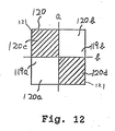
- Mirror 120 has first and second areas 119a and 119b which are arranged in the direction perpendicular to the generatrix direction 23 of cylindrical lens 24. These first and second areas 119a and 119b respectively have light masking portions 120C and 120d and reflecting portions 120a and 120b. Also, light masking portions 120c and 120d are each asymmetric about the a axis, which is in a direction parallel to the generatrix direction 23 of cylindrical lens 24, and about the b axis, which is orthogonal to the a axis, and each portion is formed in each of first and second areas 119a and 119b along the a axis. Light masking film 121 is provided on light masking portions 120c and 120d.
- mirror 120 which contains light masking portions 120C and 120d as shown in FIGURES 11
- the light irradiated onto reflecting portions 120a and 120b is reflected by mirror 120 and is led to converging lens 22.
- the light reflected by mirror 120 is processed in similar to photo detecting apparatus, as shown and described with respect to FIGURE 1A.
- the light pattern reshaping element i.e., cylindrical lens 24 is located near to photo detector 26 than the partial light extracting element, i.e., light pattern defining mask 20 (FIGURES 1A, 1B) or mirror 120 (FIGURE 11).
- the light pattern reshaping element i.e., cylindrical lens 24 is located far from photo detector 26 than the partial light extracting element, i.e., light pattern defining mask 20 or mirror 120.
- FIGURES 13A through 13D show some examples of the various modifications of light pattern defining mask 20.
- light masking portions 20c, 20d are formed by roughening so that the lights thereto are scattered and not irradiated to photo detector 26.
- light masking portions 20c, 20d are prism structures for radiating the lights out of photo detector 26.
- light pattern defining mask 20 has one light transmissive portion 20g.
- light pattern defining mask 20 has one light masking portion 20h.
- light transmissive portion 20g and light masking portion 20h can make the light passing through light pattern defining mask 20 asymmetrical.
- the present invention can provide an extremely preferable photo detecting apparatus.
Landscapes
- Physics & Mathematics (AREA)
- Optics & Photonics (AREA)
- Optical Recording Or Reproduction (AREA)
- Optical Head (AREA)
- Investigating Or Analysing Materials By Optical Means (AREA)
Applications Claiming Priority (8)
| Application Number | Priority Date | Filing Date | Title |
|---|---|---|---|
| JP327583/88 | 1988-12-27 | ||
| JP63327584A JPH02173942A (ja) | 1988-12-27 | 1988-12-27 | 光検出装置 |
| JP327580/88 | 1988-12-27 | ||
| JP327582/88 | 1988-12-27 | ||
| JP63327580A JPH02173938A (ja) | 1988-12-27 | 1988-12-27 | 光検出装置 |
| JP63327582A JPH02173940A (ja) | 1988-12-27 | 1988-12-27 | 光検出装置 |
| JP63327583A JPH02173941A (ja) | 1988-12-27 | 1988-12-27 | 光検出装置 |
| JP327584/88 | 1988-12-27 |
Publications (2)
| Publication Number | Publication Date |
|---|---|
| EP0376708A2 true EP0376708A2 (de) | 1990-07-04 |
| EP0376708A3 EP0376708A3 (de) | 1991-10-23 |
Family
ID=27480395
Family Applications (1)
| Application Number | Title | Priority Date | Filing Date |
|---|---|---|---|
| EP19890313629 Withdrawn EP0376708A3 (de) | 1988-12-27 | 1989-12-28 | Lichtfeststellungsvorrichtung |
Country Status (3)
| Country | Link |
|---|---|
| US (1) | US5036185A (de) |
| EP (1) | EP0376708A3 (de) |
| KR (1) | KR930001432B1 (de) |
Cited By (2)
| Publication number | Priority date | Publication date | Assignee | Title |
|---|---|---|---|---|
| EP0381443A3 (de) * | 1989-01-31 | 1991-10-16 | Kabushiki Kaisha Toshiba | Fokusdetektionsanordnung |
| US5253236A (en) * | 1991-10-03 | 1993-10-12 | International Business Machines Corporation | Optical beam focusing and tracking system for an optical disk information storage device |
Families Citing this family (10)
| Publication number | Priority date | Publication date | Assignee | Title |
|---|---|---|---|---|
| JP3112735B2 (ja) * | 1992-02-28 | 2000-11-27 | パイオニア株式会社 | 光ピックアップ装置 |
| US5353272A (en) * | 1992-12-29 | 1994-10-04 | Eastman Kodak Company | Apparatus and method for a modified half-aperture focus/tracking/data sensor system |
| JPH07311961A (ja) * | 1994-05-16 | 1995-11-28 | Nippon Steel Corp | 光ピックアップ |
| WO1997015923A1 (en) | 1995-10-27 | 1997-05-01 | Matsushita Electric Industrial Co., Ltd. | Optical head |
| DE19638878A1 (de) * | 1996-09-23 | 1998-03-26 | Thomson Brandt Gmbh | Aufzeichnungs- oder Wiedergabegerät zum Aufzeichnen auf oder Wiedergeben von einem optischen Aufzeichnungsträger |
| EP0951014A3 (de) * | 1998-04-14 | 2000-02-23 | Deutsche Thomson-Brandt Gmbh | Vorrichtung zum Lesen oder Beschreiben eines optischen Aufzeichnungsmediums |
| JP3781982B2 (ja) * | 2000-12-06 | 2006-06-07 | 三菱電機株式会社 | 半導体レーザ装置 |
| JP3930784B2 (ja) * | 2001-09-17 | 2007-06-13 | シャープ株式会社 | 傾斜量検出装置 |
| JP2005505880A (ja) * | 2001-10-16 | 2005-02-24 | コーニンクレッカ フィリップス エレクトロニクス エヌ ヴィ | 光走査デバイス |
| JP2004079030A (ja) * | 2002-08-12 | 2004-03-11 | Sony Corp | ディスクドライブ装置、アドレス検出方法 |
Family Cites Families (12)
| Publication number | Priority date | Publication date | Assignee | Title |
|---|---|---|---|---|
| FR2271590B1 (de) * | 1974-01-15 | 1978-12-01 | Thomson Brandt | |
| US4079247A (en) * | 1975-05-16 | 1978-03-14 | Claude Bricot | Optical focussing device |
| FR2325953A1 (fr) * | 1975-09-29 | 1977-04-22 | Thomson Brandt | Senseur optique de focalisation et dispositif de focalisation comportant un tel senseur |
| DE3280137D1 (de) * | 1981-09-17 | 1990-04-19 | Toshiba Kawasaki Kk | Ein optischer kopf. |
| US4441175A (en) * | 1982-01-25 | 1984-04-03 | Magnetic Peripherals Inc. | Partial beam focus sensing in an optical recording system |
| JPS58193335U (ja) * | 1982-06-17 | 1983-12-22 | パイオニア株式会社 | フオ−カスエラ−検出装置 |
| JPS5990237A (ja) * | 1982-11-16 | 1984-05-24 | Toshiba Corp | 光学ヘツド |
| US4604739A (en) * | 1984-04-16 | 1986-08-05 | International Business Machines Corporation | Optical focus detection employing rotated interference patterns |
| JPS61236035A (ja) * | 1985-04-09 | 1986-10-21 | Sony Corp | 光学ヘツド |
| JPS629537A (ja) * | 1985-07-08 | 1987-01-17 | Pioneer Electronic Corp | 光学式ピツクアツプ装置 |
| CA1319194C (en) * | 1986-07-28 | 1993-06-15 | Hideaki Satou | Focusing error detector and optical data detecting device incorporating the focusing error detector |
| US4816665A (en) * | 1987-08-06 | 1989-03-28 | Maxtor Corporation | Sensor array for focus detection |
-
1989
- 1989-12-26 US US07/456,427 patent/US5036185A/en not_active Expired - Fee Related
- 1989-12-27 KR KR1019890019862A patent/KR930001432B1/ko not_active Expired - Fee Related
- 1989-12-28 EP EP19890313629 patent/EP0376708A3/de not_active Withdrawn
Cited By (2)
| Publication number | Priority date | Publication date | Assignee | Title |
|---|---|---|---|---|
| EP0381443A3 (de) * | 1989-01-31 | 1991-10-16 | Kabushiki Kaisha Toshiba | Fokusdetektionsanordnung |
| US5253236A (en) * | 1991-10-03 | 1993-10-12 | International Business Machines Corporation | Optical beam focusing and tracking system for an optical disk information storage device |
Also Published As
| Publication number | Publication date |
|---|---|
| EP0376708A3 (de) | 1991-10-23 |
| US5036185A (en) | 1991-07-30 |
| KR900010683A (ko) | 1990-07-09 |
| KR930001432B1 (ko) | 1993-02-27 |
Similar Documents
| Publication | Publication Date | Title |
|---|---|---|
| US5036185A (en) | Optical apparatus for detecting a focusing state | |
| JPS60263341A (ja) | 光学ヘツド | |
| JPS58100248A (ja) | 光学的情報記録媒体 | |
| CA1303738C (en) | Optical information recording and reproducing apparatus | |
| JPS6245614B2 (de) | ||
| EP1067532B1 (de) | Optische Abtasteinheit und optisches Plattengerät | |
| JP2912052B2 (ja) | 焦点検出装置 | |
| JPH02173942A (ja) | 光検出装置 | |
| JP2746593B2 (ja) | 光学式情報読み取り装置 | |
| JP3202073B2 (ja) | 光学的情報記録再生装置 | |
| JPH02173939A (ja) | 光検出装置 | |
| JPS605431A (ja) | 情報記録媒体の傾き検出方式 | |
| JPH02173941A (ja) | 光検出装置 | |
| JP2002184025A (ja) | 情報記録再生装置 | |
| JPS62239333A (ja) | トラツキング信号検出方法 | |
| JPS60167132A (ja) | 光情報検出装置 | |
| JPH02172032A (ja) | 光検出装置 | |
| JPS61240442A (ja) | 光学的情報処理装置 | |
| JPS63855B2 (de) | ||
| JPS61122936A (ja) | 焦点検出装置 | |
| JPH02173940A (ja) | 光検出装置 | |
| JPH05314510A (ja) | 分離型光ピックアップ装置 | |
| JPH04245038A (ja) | 光学的情報記録装置 | |
| JPH0636249B2 (ja) | 光学ヘッド | |
| JPS6010424A (ja) | 光学ヘツド |
Legal Events
| Date | Code | Title | Description |
|---|---|---|---|
| PUAI | Public reference made under article 153(3) epc to a published international application that has entered the european phase |
Free format text: ORIGINAL CODE: 0009012 |
|
| 17P | Request for examination filed |
Effective date: 19900126 |
|
| AK | Designated contracting states |
Kind code of ref document: A2 Designated state(s): DE FR NL |
|
| PUAL | Search report despatched |
Free format text: ORIGINAL CODE: 0009013 |
|
| AK | Designated contracting states |
Kind code of ref document: A3 Designated state(s): DE FR NL |
|
| 17Q | First examination report despatched |
Effective date: 19931006 |
|
| STAA | Information on the status of an ep patent application or granted ep patent |
Free format text: STATUS: THE APPLICATION IS DEEMED TO BE WITHDRAWN |
|
| 18D | Application deemed to be withdrawn |
Effective date: 19950529 |