EP0385459A2 - Gerät zur Synchronisierkontrolle - Google Patents
Gerät zur Synchronisierkontrolle Download PDFInfo
- Publication number
- EP0385459A2 EP0385459A2 EP90103971A EP90103971A EP0385459A2 EP 0385459 A2 EP0385459 A2 EP 0385459A2 EP 90103971 A EP90103971 A EP 90103971A EP 90103971 A EP90103971 A EP 90103971A EP 0385459 A2 EP0385459 A2 EP 0385459A2
- Authority
- EP
- European Patent Office
- Prior art keywords
- synchronizing
- value
- command value
- pair
- synchronizing error
- Prior art date
- Legal status (The legal status is an assumption and is not a legal conclusion. Google has not performed a legal analysis and makes no representation as to the accuracy of the status listed.)
- Withdrawn
Links
Images


Classifications
-
- G—PHYSICS
- G05—CONTROLLING; REGULATING
- G05B—CONTROL OR REGULATING SYSTEMS IN GENERAL; FUNCTIONAL ELEMENTS OF SUCH SYSTEMS; MONITORING OR TESTING ARRANGEMENTS FOR SUCH SYSTEMS OR ELEMENTS
- G05B19/00—Program-control systems
- G05B19/02—Program-control systems electric
- G05B19/18—Numerical control [NC], i.e. automatically operating machines, in particular machine tools, e.g. in a manufacturing environment, so as to execute positioning, movement or co-ordinated operations by means of program data in numerical form
- G05B19/182—Numerical control [NC], i.e. automatically operating machines, in particular machine tools, e.g. in a manufacturing environment, so as to execute positioning, movement or co-ordinated operations by means of program data in numerical form characterised by the machine tool function, e.g. thread cutting, cam making, tool direction control
-
- G—PHYSICS
- G05—CONTROLLING; REGULATING
- G05B—CONTROL OR REGULATING SYSTEMS IN GENERAL; FUNCTIONAL ELEMENTS OF SUCH SYSTEMS; MONITORING OR TESTING ARRANGEMENTS FOR SUCH SYSTEMS OR ELEMENTS
- G05B2219/00—Program-control systems
- G05B2219/30—Nc systems
- G05B2219/49—Nc machine tool, till multiple
- G05B2219/49252—Two spindle drives for common workpiece
-
- G—PHYSICS
- G05—CONTROLLING; REGULATING
- G05B—CONTROL OR REGULATING SYSTEMS IN GENERAL; FUNCTIONAL ELEMENTS OF SUCH SYSTEMS; MONITORING OR TESTING ARRANGEMENTS FOR SUCH SYSTEMS OR ELEMENTS
- G05B2219/00—Program-control systems
- G05B2219/30—Nc systems
- G05B2219/50—Machine tool, machine tool null till machine tool work handling
- G05B2219/50234—Synchronize two spindles, axis, electronic transmission, line shafting
Definitions
- the present invention relates to a synchronizing control apparatus capable of synchronously rotating two rotary spindles. More particularly, it relates to a synchronizing control apparatus which is used in a machine tool, for example, a pin grinder for a crankshaft of an engine, wherein two main spindles supporting a workpiece are synchronously rotated.
- left side main spindle and right side main spindle supporting a workpiece are mechanically connected each other through a synchronizing shaft in order to be synchronously rotated.
- the pin grinder In the pin grinder, however, it is difficult to transmit the same driving power to the workpiece from the two main spindles, because transmission losses in drive trains which transmit a driving power from a drive motor to respective main spindles are different each other. Namely, the transmission loss in one of the drive trains which transmits the driving power directly to one of the main spindles is smaller than the transmission loss in the other drive train which transmits the driving power to the other main spindle via the synchronizing shaft. Further, it is difficult to perfectly synchronize the two main spindles due to backlashes of gears and the like in the drive trains. Therefore, the prior pin grinder has a difficulty in improving the dimensional accuracy and surface roughness of machined workpieces.
- an apparatus wherein master and slave rotary spindles, which are mechanically separated, are driven by a pair of servomotors each provided with a position sensor for detecting angular positions thereof.
- the command signals which are the same in principle, are applied to a pair of drive circuits driving respective servomotors in order to rotate the two rotary spindles synchronously.
- a synchronous error i.e., a rotational position difference between the master and slave spindles is produced
- the command signal for the slave spindle is compensated based upon the synchronizing error in order to reduce the synchronizing error.
- the compensation of the command signal is executed whenever the command signals are output to the drive circuits.
- the pin grinder provided with the electrical synchronizing apparatus has a problem of instability which occurs due to an interference of driving powers from the pair of servomotors. Since the pair of servomotors driving the pair of main spindles are connected with each other through a workpiece, whose both end are secured to respective main spindles, the driving power transmitted from one of the servomotors to the workpiece is transmitted to the other servomotor through the workpiece, so that the driving powers from the pair of servomotors interfere each other.
- Another object of the present invention is to provide an improved synchronizing control apparatus capable of eliminating hunting conditions, which cause an instable condition of the control apparatus.
- a further object of the present invention is to provide a improved synchronizing control apparatus capable of minimizing the synchronizing error between two rotary spindles, thereby enabling the control apparatus to accurately synchronize the two rotary spindles.
- synchronizing error detecting means for detecting a synchronizing error between the two rotary spindles, which are not mechanically connected
- control means for applying a command signal to a drive circuit for one of the two rotary spindles (master spindle) and for applying a compensated command signal to a drive circuit for the other of the two rotary spindles (slave spindle).
- the compensated command signal is calculated based upon the command signal and a synchronizing error at an interval that is longer than the length of instable condition of the servo loop of the other rotary spindle (slave spindle), which occurs after a new command signal being applied.
- control apparatus is provided with comparing means for comparing the detected synchronizing error with a predetermined limit value; limiting means for regarding the synchronizing error as a final compensation adding value when the synchronizing error is smaller that the limit value and for regarding the limit value as the final compensation adding value when the synchronizing error is larger than the limit value; and compensation value calculating means for adding the final compensation adding value to a previous compensation value to obtain a new compensation value. Accordingly, the compensated command signal applied to the other rotary spindle (slave spindle) is gradually varied even if the synchronizing error between the two rotary spindles suddenly increases, thereby instable conditions which is caused due to abrupt changes of the compensation value being eliminated.
- FIG. 1 a pin grinder provided with a synchronizing control apparatus according to the present invention is shown.
- a table 11 is guided on a bed 10 of the grinder at its front side to be movable in a Z-axis direction ( lateral direction in FIG. 1).
- the table 11 is moved by a feed screw which is rotated by a servomotor 12 fixed to a lateral side of the bed 10.
- a pair of spindle heads 14 and 15 are mounted on both lateral ends of the table 11.
- a pair of main spindles 18 and 19 having eccentric chuck devices 16 and 17 are supported by the spindle heads 14 and 15 to be rotated by spindle motors 20 and 21 in the form of servomotors, respectively.
- Rotary encoders 22 and 23 are attached, as angular position sensors, to respective spindle motors 20 and 21 so as to detect rotational positions of the main spindles 18 and 19.
- a crankshaft of an engine is supported as a workpiece W, with its journal portions located opposite ends being held by the eccentric chuck devices 16 and 17, in order to be rotated about the axis of a pin portion to be machined.
- the left-side main spindle 18 is hereinafter referred to as master main spindle
- the right-side main spindle 19 is hereinafter referred to as slave main spindle.
- the rotation of the slave main spindle 19 is controlled so as to follow the master main spindle 18. Therefore, the master main spindle 18 and the slave main spindle 19 are rotated as if one spindle.
- a wheel head 25 is guided on the rear side of the bed 1 to be movable in an X-axis direction perpendicular to the rotational axis of the main spindle 18.
- the wheel head 25 is moved by a servomotor 26 attached to the back surface of the bed 10 through a feed screw 27.
- a grinding wheel G is supported on the grinding head 25 to be rotated by a grinding wheel drive motor 28 about an axis parallel to the main spindle 18.
- a rest device 30 is mounted on the front side of the bed 10 in order to face the pin portion of the workpiece W to be ground.
- the contacting shoe 31 of the rest device 30 is moved toward the grinding wheel G in an I-axis parallel to the X-axis by a servomotor 32 so as to contacts with the pin portion to be ground, thereby deflection of the workpiece W being eliminated.
- the servomotors 12, 26 and 32 and the spindle motors 20 and 21 are connected to the servomotor driving circuits 41 through 45 so as to be rotated in accordance with command signals from the numerical control apparatus (NC controller) 50.
- NC controller numerical control apparatus
- the numerical control apparatus 50 is provided with a main CPU 51, a ROM 52 memorizing a control program, a RAM 53 memorizing NC data etc, and an interface circuit 54, to which a tape reader 61, a CRT display apparatus 62, a keyboard 63 and an operation panel 64 are connected.
- the numerical control apparatus 50 is provided with a drive CPU 56, which is connected to the main CPU 51 through a RAM 57. Also, detection signals from the rotary encoders 22 and 23, which detect rotational angle positions of the main spindles 18 and 19, are input to the drive CPU 56 through an interface circuit 55.
- the drive CPU 56 is connected to a pulse distribution circuit 58 and a digital-to-analog converting circuit 59 (hereinafter referred to as D/A converting circuit).
- the pulse distribution circuit 58 distributes command pulses to the dive circuits 41, 42 and 45 in accordance with pulse distribution commands output by the drive CPU 56.
- the D/A converting circuit 59 converts digital command values to analog command signals, which are output to the drive circuits 43 and 44.
- the drive circuits 41, 42 and 45 rotate the servomotor 12, 26 and 32, respectively, in accordance with the command pulses output from the pulse distribution circuit 58, so that the table 11, the wheel head 25 and the contacting shoe 31 are moved by programmed amounts.
- the drive circuits 43 and 44 rotate the servomotors 20 and 21, respectively, at speeds corresponding to analog command signals output from the D/A converting circuit 59.
- the main CPU 51 executes an interpolation in accordance with the NC data stored in the RAM 53 so as to obtain a series of target positions to which the main spindles 18 and 19 have to reach.
- the series of the target positions are sequentially output from the main CPU 51 to a target position area of the RAM 53.
- the drive CPU 56 executes a synchronizing control program as shown in FIG. 2 at a predetermined time interval, for example, 10 milliseconds.
- a new target position is read from the target position area of the RAM 57 by the drive CPU 56, and position signals output from the rotary encoders 22 and 23 are read at step 102 in order to detect present positions of the master and slave main spindles 18 and 19.
- the positional differences between the new target angular position and the present angular positions of the master and slave main spindle 18 and 19 are calculated at steps 103 and 104, respectively. These calculated positional difference are regarded as command values.
- a compensation value is calculated based upon a synchronizing error between the master main spindle 18 and the slave main spindle 19.
- the calculated compensation value is added to the command value for the slave main spindle 19 calculated at the step 104 so as to obtain a compensated command value.
- the command value for the master main spindle 18 calculated at the step 103 is output to the the dive circuit 43 through the D/A converting circuit 59 as it is, in order to rotate the master main spindle 18 at a speed corresponding to the command value.
- the compensated command value calculated at the step 105 is output to the drive circuit 44 through the D/A converting circuit 59 in order to rotate the slave main spindle 19 at a speed corresponding to the compensated command value.
- FIG. 3 is a detailed flow chart showing the compensation value calculation process in the step 105.
- calculation of the compensation value and renewal thereof are executed at a predetermined time interval.
- data for setting the time interval is input from the keyboard 63, in order to be memorized in an interval memorizing area IMA of the RAM 57.
- a predetermined time period corresponding to the time interval has passed by checking the contents of the time counter TC (not shown).
- the time counter is preset, at step 207, to a predetermined initial value corresponding to the time interval memorized in the memory area IMA of the RAM 57. If the contents of the time counter TC is not zero, it is judged that the predetermined time has not passed yet, and the process goes to step 210. As a result, the time counter TC is incremented before returning back to the main routine.
- the content of the time counter becomes zero after repeated executions of the step 210, it is judged at the step 201 that the predetermined time period has passed, and the process goes to step 202.
- a synchronizing error between the main and slave main spindles is calculated depending upon the angular positions read at the step 102 from the rotary encoders 22 and 23.
- a compensation adding value is calculated at step 203 based upon the synchronizing error.
- the compensation adding value is a value obtained by multiplying the synchronizing error by a constant. Therefore, the compensation adding value can be positive and negative.
- the compensation adding value is compared with a predetermined limit value LV, which is input to the main CPU through the keyboard 63 in order to be stored in the RAM 57.
- the limit value LV indicates an allowable maximum change of the compensation value within the time interval. If the calculated compensation adding value is larger than the limit value, the process goes to step 205 in order to replace the compensation adding value calculated at the step 203 with the predetermined limit value LV, so that the limit value LV is regarded as the compensation adding value. Thereafter, the process goes to step 206. On the other hand, if the calculated compensation adding value is equal to or smaller than the limit value, the process goes directly to the step 206.
- a new compensation value is obtained by adding the compensation adding value to the previous compensation value. Thereafter, the process goes to the step 106 in FIG. 2 after decrementing the time counter TC at step 207.
- the new compensation value calculated by the process shown in FIG. 3 is used at the step 106 in order to compensate the command value for the slave main spindle 19.
- the slave main spindle 19 is rotated at a speed corresponding to the compensated command value while the master main spindle 18 is rotated at a speed corresponding to the command value, thereby the master and slave main spindles 18 and 19 being synchronized.
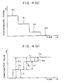
- FIG. 4 (a), (b) are charts showing the changes of the synchronizing error and the compensation value.
- the compensation value is renewed at a predetermined interval as explained above.
- the compensation value D0 calculated at step 203 based upon the synchronizing error A0 becomes larger than the limit value LV.
- the compensation value D0 is replaced with the limit value LV at the step 205.
- the limit value LV becomes a final compensation adding value C0. Since the initial compensation value is zero in this case, the value C0 becomes a final compensation value by which the command value for the slave main spindle 19 is compensated.
- the synchronizing error decreases from A0 to A1.
- the compensation adding value B1 calculated from the synchronizing error A1 becomes larger than the limit value LV. Therefore, the limit value LV is again used as a final adding value for the calculation of the compensation value. As a result, a value C1 obtained by adding the limit value LV to the previous compensation value C0 is now used as a final compensation value in order to reduce the synchronizing error. By this renewal of the compensation value, the synchronizing error is reduced from A1 to A2.
- the compensation adding values are cumulated in order to obtain a new compensation value.
- the command value for the slave main spindle is gradually compensated, even if a large synchronizing error is produced, in order to minimize the disturbance of the spindle motor 21. Therefore, it is possible to improve the synchronizing accuracy.
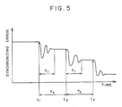
- FIG. 5 is a chart showing the change of the synchronizing error.
- the compensation value is renewed at an interval T0, which has input from the keyboard 63.
- the servo loop for the slave main spindle 19 falls into an instable condition for a period T1 until the synchronizing error becomes a value corresponding to the new compensation value.
- a similar instable condition also occurs in the servo loop for the master main spindle 18. Since the main and slave main spindles 18 and 19 are connected mechanically through the workpiece W, the both main spindles 18 and 19 interfere each other, thereby the left-side spindle motor 20 also falling into a hunting condition. This transitional hunting condition decrease in a short period, after which the servo loops move to stable conditions.
- the compensation value is renewed at the interval T0 longer than the instable period T1 of the servo loop, a new compensation adding value is calculated based upon a synchronizing error detected in the stable condition. Accordingly, it is possible to prevent the apparatus from calculating the compensation value adding value based upon a synchronizing error detected in the instable condition, wherein the left-side and right-side main spindles 18 and 19 are in instable conditions such as hunting conditions. Therefore, it is possible to eliminate the hunting conditions, and thereby to reduce time wherein the left-side and right-side main spindles 18 and 19 are in instable conditions.
- the interval T0 is set at, for example, 100 through 200 milliseconds. Since the command values are output from the drive CPU 56 to the D/A converting circuit 58, at steps 107 and 108, every 10 milliseconds, the compensation value is renewed whenever 10 through 20 command values are output to the D/A converting circuit 58.
- the length T1 of the instable condition changes depending upon the weight and inertia moment of the workpiece W supported between the left-side and right-side main spindles 18 and 10. Accordingly, an ideal synchronizing control can be realized by setting an optimum time interval for the renewal process through the keyboard 63.
- the synchronizing control apparatus is used for synchronizing rotations of the left-side and right-side main spindles of a pin grinder
- the present invention can be used for synchronizing two non-connected spindles, such as a wheel spindle supporting a grinding wheel and a work spindle supporting a workpiece of a gear grinder or a cam grinder and the like, in which the grinding wheel and the workpiece are rotated synchronously.
- a synchronizing control apparatus for synchronously rotating master and slave main spindles of a pin grinder wherein a servomotor for the slave main spindle is rotated at a speed corresponding to a compensated command value while the master main spindle is rotated at a speed corresponding to a noncompensated command value.
- the compensated command value is calculated based on a synchronizing error between the master and slave main spindles at a predetermined interval longer than the length of instable condition of a servo loop for the slave main spindle.
- the command value for the slave main spindle is gradually compensated in order to prevent the compensated command value from changing too abruptly.
Landscapes
- Engineering & Computer Science (AREA)
- Human Computer Interaction (AREA)
- Manufacturing & Machinery (AREA)
- Physics & Mathematics (AREA)
- General Physics & Mathematics (AREA)
- Automation & Control Theory (AREA)
- Numerical Control (AREA)
- Constituent Portions Of Griding Lathes, Driving, Sensing And Control (AREA)
Applications Claiming Priority (4)
| Application Number | Priority Date | Filing Date | Title |
|---|---|---|---|
| JP5048589A JPH0797916B2 (ja) | 1989-03-02 | 1989-03-02 | 同期制御装置 |
| JP50485/89 | 1989-03-02 | ||
| JP58563/89 | 1989-03-10 | ||
| JP1058563A JPH0763226B2 (ja) | 1989-03-10 | 1989-03-10 | 同期制御装置 |
Publications (2)
| Publication Number | Publication Date |
|---|---|
| EP0385459A2 true EP0385459A2 (de) | 1990-09-05 |
| EP0385459A3 EP0385459A3 (de) | 1990-11-14 |
Family
ID=26390956
Family Applications (1)
| Application Number | Title | Priority Date | Filing Date |
|---|---|---|---|
| EP19900103971 Withdrawn EP0385459A3 (de) | 1989-03-02 | 1990-03-01 | Gerät zur Synchronisierkontrolle |
Country Status (2)
| Country | Link |
|---|---|
| US (1) | US5175680A (de) |
| EP (1) | EP0385459A3 (de) |
Cited By (6)
| Publication number | Priority date | Publication date | Assignee | Title |
|---|---|---|---|---|
| DE19626189A1 (de) * | 1996-06-29 | 1998-01-02 | Schaudt Maschinenbau Gmbh | Verfahren zum Schleifen rotierender Werkstücke |
| GB2353488A (en) * | 1999-06-04 | 2001-02-28 | Unova Uk Ltd | Surface forming of metal components |
| WO2004097538A1 (de) * | 2003-04-25 | 2004-11-11 | Focke & Co. (Gmbh & Co. Kg) | Verfahren und vorrichtung zur steuerung einer fertigungseinheit |
| EP1503260A1 (de) * | 2003-07-28 | 2005-02-02 | Fanuc Ltd | Numerische Steuerungseinrichtung |
| CN112296761A (zh) * | 2019-07-26 | 2021-02-02 | 奕达精机股份有限公司 | 双主轴加工机及其主轴补偿方法 |
| DE102022127173A1 (de) | 2022-10-18 | 2024-04-18 | Zinner GmbH Präzisionswerkzeuge | Werkzeughalter, umfassend eine Aluminiumlegierung |
Families Citing this family (17)
| Publication number | Priority date | Publication date | Assignee | Title |
|---|---|---|---|---|
| US5222017A (en) * | 1990-11-23 | 1993-06-22 | The University Of British Columbia | Control system to synchronize slave computers |
| US5519602A (en) * | 1993-08-02 | 1996-05-21 | The University Of British Columbia | Multiple slave control |
| DE19626287A1 (de) * | 1996-07-01 | 1997-02-13 | Abb Management Ag | Verfahren zum Betrieb eines Antriebssystems und Vorrichtung zur Durchführung des Verfahrens |
| JP3453043B2 (ja) * | 1997-04-30 | 2003-10-06 | 東芝機械株式会社 | 旋回機構の数値制御装置 |
| JP4346824B2 (ja) * | 1998-12-24 | 2009-10-21 | 三菱電機株式会社 | 数値制御装置 |
| JP3665008B2 (ja) * | 2001-10-25 | 2005-06-29 | ファナック株式会社 | 同期制御方法及び同期制御装置 |
| JP3680064B2 (ja) * | 2003-04-21 | 2005-08-10 | ファナック株式会社 | 数値制御装置 |
| JP4473033B2 (ja) * | 2004-04-21 | 2010-06-02 | 株式会社小森コーポレーション | 同期制御方法及び装置 |
| JP4070744B2 (ja) * | 2004-04-28 | 2008-04-02 | ファナック株式会社 | 同期制御装置 |
| JP2005322076A (ja) * | 2004-05-10 | 2005-11-17 | Fanuc Ltd | 数値制御装置 |
| JP5032081B2 (ja) * | 2006-09-29 | 2012-09-26 | オークマ株式会社 | 工作機械における加工制御方法及び加工情報作成方法 |
| JP2008225533A (ja) * | 2007-03-08 | 2008-09-25 | Fanuc Ltd | サーボ制御装置 |
| DE112010002745T5 (de) * | 2009-05-04 | 2013-06-27 | Mori Seiki Co., Ltd. | System und Verfahren zum synchronisierten Bearbeiten |
| JP6088581B2 (ja) * | 2015-06-04 | 2017-03-01 | ファナック株式会社 | 主軸と送り軸との同期運転を制御する工作機械の制御装置及び制御方法 |
| US10250170B2 (en) | 2016-08-24 | 2019-04-02 | Mitsubishi Electric Corporation | Motor control device |
| CN112947138A (zh) * | 2021-01-21 | 2021-06-11 | 南京音飞储存设备(集团)股份有限公司 | 一种双轴同步控制单元及控制方法 |
| CN118527683B (zh) * | 2023-12-19 | 2024-12-06 | 杭州方兴表业有限公司 | 一种数控走芯式双主轴车铣复合加工中心及加工方法 |
Family Cites Families (18)
| Publication number | Priority date | Publication date | Assignee | Title |
|---|---|---|---|---|
| US4000449A (en) * | 1974-10-22 | 1976-12-28 | Westinghouse Electric Corporation | Electrical shaft system |
| DE2721634C3 (de) * | 1977-05-13 | 1980-01-31 | Danfoss A/S, Nordborg (Daenemark) | Drehzahlverhältnis-Regelanordnung |
| JPS5653588A (en) * | 1979-10-09 | 1981-05-13 | Fanuc Ltd | Main shaft rotation control system |
| JPS57189750A (en) * | 1981-05-19 | 1982-11-22 | Yaskawa Electric Mfg Co Ltd | Nc machine tool provided with sliding error correction capacity |
| JPS5835607A (ja) * | 1981-08-27 | 1983-03-02 | Fanuc Ltd | 数値制御装置 |
| JPS58139201A (ja) * | 1982-02-12 | 1983-08-18 | Toyota Central Res & Dev Lab Inc | サ−ボ系用異常検出装置 |
| JPS59172013A (ja) * | 1983-03-22 | 1984-09-28 | Mitsubishi Electric Corp | 数値制御装置の刃物台同期方式 |
| US4554774A (en) * | 1983-04-30 | 1985-11-26 | Shibuya Kogyo Co., Ltd. | System for synchronizing two or more process units |
| GB2156100B (en) * | 1984-02-14 | 1987-11-25 | Toshiba Machine Co Ltd | Method and system for controlling synchronous drive systems |
| JPS61143803A (ja) * | 1984-12-17 | 1986-07-01 | Toshiba Corp | ロボツトの制御装置 |
| DE3534820A1 (de) * | 1985-09-30 | 1987-04-02 | Herlan & Co Maschf | Verfahren und vorrichtung zum erzeugen eines taktsynchronen gleichlaufs bei einzeln angetriebenen maschinen und/oder maschinengruppen einer produktionsanlage |
| JPH0692057B2 (ja) * | 1987-08-25 | 1994-11-16 | 豊田工機株式会社 | 数値制御工作機械 |
| EP0309824B1 (de) * | 1987-09-28 | 1991-11-13 | Siemens Aktiengesellschaft | Verfahren zur numerisch gesteuerten Lageregelung elektromotorisch angetriebener Achsen |
| US4999557A (en) * | 1988-05-02 | 1991-03-12 | Shinko Electric Co., Ltd. | Integration proportional controller in servo-control system |
| JPH0226301A (ja) * | 1988-07-12 | 1990-01-29 | Teijin Seiki Co Ltd | サーボ制御装置 |
| JPH0772842B2 (ja) * | 1988-07-29 | 1995-08-02 | オ−クマ株式会社 | 追従誤差の検出機能を持った数値制御装置 |
| JPH0649260B2 (ja) * | 1989-02-28 | 1994-06-29 | 豊田工機株式会社 | 同期制御装置 |
| JP2581797B2 (ja) * | 1989-04-27 | 1997-02-12 | オ−クマ株式会社 | 同期制御方法及びその装置 |
-
1990
- 1990-03-01 EP EP19900103971 patent/EP0385459A3/de not_active Withdrawn
- 1990-03-02 US US07/487,449 patent/US5175680A/en not_active Expired - Lifetime
Cited By (10)
| Publication number | Priority date | Publication date | Assignee | Title |
|---|---|---|---|---|
| DE19626189A1 (de) * | 1996-06-29 | 1998-01-02 | Schaudt Maschinenbau Gmbh | Verfahren zum Schleifen rotierender Werkstücke |
| GB2353488A (en) * | 1999-06-04 | 2001-02-28 | Unova Uk Ltd | Surface forming of metal components |
| GB2353488B (en) * | 1999-06-04 | 2002-03-20 | Unova Uk Ltd | Surface forming of metal components |
| WO2004097538A1 (de) * | 2003-04-25 | 2004-11-11 | Focke & Co. (Gmbh & Co. Kg) | Verfahren und vorrichtung zur steuerung einer fertigungseinheit |
| DE10319064A1 (de) * | 2003-04-25 | 2004-11-11 | Focke & Co.(Gmbh & Co. Kg) | Verfahren und Vorrichtung zur Steuerung einer Fertigungseinheit |
| US7298111B2 (en) | 2003-04-25 | 2007-11-20 | Focke & Co. (Gmbh & Co. Kg) | Method and device for controlling a production unit |
| EP1503260A1 (de) * | 2003-07-28 | 2005-02-02 | Fanuc Ltd | Numerische Steuerungseinrichtung |
| CN100394334C (zh) * | 2003-07-28 | 2008-06-11 | 发那科株式会社 | 数值控制装置 |
| CN112296761A (zh) * | 2019-07-26 | 2021-02-02 | 奕达精机股份有限公司 | 双主轴加工机及其主轴补偿方法 |
| DE102022127173A1 (de) | 2022-10-18 | 2024-04-18 | Zinner GmbH Präzisionswerkzeuge | Werkzeughalter, umfassend eine Aluminiumlegierung |
Also Published As
| Publication number | Publication date |
|---|---|
| EP0385459A3 (de) | 1990-11-14 |
| US5175680A (en) | 1992-12-29 |
Similar Documents
| Publication | Publication Date | Title |
|---|---|---|
| US5175680A (en) | Synchronizing control apparatus | |
| EP1742128B1 (de) | Servosteuerung | |
| EP0464496B1 (de) | Verfahren zum Synchronisieren sich simultan bewegender Vorschubachsen einer Drehbank | |
| EP1143316B1 (de) | Nc-werkzeugmaschine und verfahren zur steuerung der nc-werkzeugmaschine | |
| JPWO2001029628A1 (ja) | 数値制御工作機械の制御方法及び数値制御工作機械 | |
| US5404308A (en) | Numerical control (NC) device to control feed speed of tool based on speed of spindle and amount of change of spindle speed | |
| US4963805A (en) | Numerical control apparatus for machining non-circular workpieces | |
| EP0268887B1 (de) | Numerische Vorschubeinrichtung für eine Werkzeugmaschine | |
| EP1293852B1 (de) | Verfahren zur Kompensation von Profildaten sowie numerische Steuerung und Werkzeugmaschine zur Durchführung des Verfahrens | |
| KR19990083577A (ko) | 절삭공구를갖는오비트가공의서보제어방법및오비트가공의서보제어계 | |
| KR20010041353A (ko) | 동기제어장치 | |
| EP0474882B1 (de) | Numerische steuerung | |
| EP0886811B1 (de) | Verbessertes überwachungssystem für die bewegung eines werkzeugs und werkzeugschlittens | |
| GB2061554A (en) | Control System for Producing Crankshafts | |
| JPH0132011B2 (de) | ||
| JPH0649260B2 (ja) | 同期制御装置 | |
| JP7469466B2 (ja) | 工作機械の制御装置、制御システム | |
| JPH08110808A (ja) | 数値制御工作機械の制御方法及び装置 | |
| JP3994378B2 (ja) | 数値制御装置およびそのピッチエラー補正方法 | |
| JP3927264B2 (ja) | トルク一定同期駆動制御装置 | |
| JPH05318283A (ja) | 工具たわみ補正方式 | |
| JPH02160457A (ja) | 工作機械の真直度補正装置 | |
| JPH02241392A (ja) | 同期制御装置 | |
| JP3163792B2 (ja) | 数値制御研削盤 | |
| JPH0797916B2 (ja) | 同期制御装置 |
Legal Events
| Date | Code | Title | Description |
|---|---|---|---|
| PUAI | Public reference made under article 153(3) epc to a published international application that has entered the european phase |
Free format text: ORIGINAL CODE: 0009012 |
|
| AK | Designated contracting states |
Kind code of ref document: A2 Designated state(s): DE FR GB IT SE |
|
| PUAL | Search report despatched |
Free format text: ORIGINAL CODE: 0009013 |
|
| AK | Designated contracting states |
Kind code of ref document: A3 Designated state(s): DE FR GB IT SE |
|
| RHK1 | Main classification (correction) |
Ipc: G05D 13/64 |
|
| 17P | Request for examination filed |
Effective date: 19910412 |
|
| 17Q | First examination report despatched |
Effective date: 19930609 |
|
| STAA | Information on the status of an ep patent application or granted ep patent |
Free format text: STATUS: THE APPLICATION IS DEEMED TO BE WITHDRAWN |
|
| 18D | Application deemed to be withdrawn |
Effective date: 19940728 |