EP0388035A2 - Appareil de commande de blocage de roue - Google Patents
Appareil de commande de blocage de roue Download PDFInfo
- Publication number
- EP0388035A2 EP0388035A2 EP90301950A EP90301950A EP0388035A2 EP 0388035 A2 EP0388035 A2 EP 0388035A2 EP 90301950 A EP90301950 A EP 90301950A EP 90301950 A EP90301950 A EP 90301950A EP 0388035 A2 EP0388035 A2 EP 0388035A2
- Authority
- EP
- European Patent Office
- Prior art keywords
- wheel
- pressure
- brake pressure
- brake
- condition
- Prior art date
- Legal status (The legal status is an assumption and is not a legal conclusion. Google has not performed a legal analysis and makes no representation as to the accuracy of the status listed.)
- Granted
Links
- 238000011084 recovery Methods 0.000 claims abstract description 33
- 238000000034 method Methods 0.000 claims description 12
- 230000004044 response Effects 0.000 claims description 9
- 238000001514 detection method Methods 0.000 claims description 2
- 230000000694 effects Effects 0.000 description 14
- 238000010586 diagram Methods 0.000 description 9
- 230000006870 function Effects 0.000 description 7
- 230000001133 acceleration Effects 0.000 description 6
- 238000013459 approach Methods 0.000 description 6
- 230000003247 decreasing effect Effects 0.000 description 6
- 230000007423 decrease Effects 0.000 description 5
- 239000012530 fluid Substances 0.000 description 3
- 238000004891 communication Methods 0.000 description 2
- 230000001351 cycling effect Effects 0.000 description 2
- 230000000977 initiatory effect Effects 0.000 description 2
- 230000035807 sensation Effects 0.000 description 2
- 239000006227 byproduct Substances 0.000 description 1
- 238000004364 calculation method Methods 0.000 description 1
- 230000001419 dependent effect Effects 0.000 description 1
- 230000010365 information processing Effects 0.000 description 1
- 230000000087 stabilizing effect Effects 0.000 description 1
Images

Classifications
-
- B—PERFORMING OPERATIONS; TRANSPORTING
- B60—VEHICLES IN GENERAL
- B60T—VEHICLE BRAKE CONTROL SYSTEMS OR PARTS THEREOF; BRAKE CONTROL SYSTEMS OR PARTS THEREOF, IN GENERAL; ARRANGEMENT OF BRAKING ELEMENTS ON VEHICLES IN GENERAL; PORTABLE DEVICES FOR PREVENTING UNWANTED MOVEMENT OF VEHICLES; VEHICLE MODIFICATIONS TO FACILITATE COOLING OF BRAKES
- B60T8/00—Arrangements for adjusting wheel-braking force to meet varying vehicular or ground-surface conditions, e.g. limiting or varying distribution of braking force
- B60T8/17—Using electrical or electronic regulation means to control braking
- B60T8/176—Brake regulation specially adapted to prevent excessive wheel slip during vehicle deceleration, e.g. ABS
- B60T8/1761—Brake regulation specially adapted to prevent excessive wheel slip during vehicle deceleration, e.g. ABS responsive to wheel or brake dynamics, e.g. wheel slip, wheel acceleration or rate of change of brake fluid pressure
- B60T8/17616—Microprocessor-based systems
-
- B—PERFORMING OPERATIONS; TRANSPORTING
- B60—VEHICLES IN GENERAL
- B60T—VEHICLE BRAKE CONTROL SYSTEMS OR PARTS THEREOF; BRAKE CONTROL SYSTEMS OR PARTS THEREOF, IN GENERAL; ARRANGEMENT OF BRAKING ELEMENTS ON VEHICLES IN GENERAL; PORTABLE DEVICES FOR PREVENTING UNWANTED MOVEMENT OF VEHICLES; VEHICLE MODIFICATIONS TO FACILITATE COOLING OF BRAKES
- B60T8/00—Arrangements for adjusting wheel-braking force to meet varying vehicular or ground-surface conditions, e.g. limiting or varying distribution of braking force
- B60T8/32—Arrangements for adjusting wheel-braking force to meet varying vehicular or ground-surface conditions, e.g. limiting or varying distribution of braking force responsive to a speed condition, e.g. acceleration or deceleration
- B60T8/34—Arrangements for adjusting wheel-braking force to meet varying vehicular or ground-surface conditions, e.g. limiting or varying distribution of braking force responsive to a speed condition, e.g. acceleration or deceleration having a fluid pressure regulator responsive to a speed condition
- B60T8/42—Arrangements for adjusting wheel-braking force to meet varying vehicular or ground-surface conditions, e.g. limiting or varying distribution of braking force responsive to a speed condition, e.g. acceleration or deceleration having a fluid pressure regulator responsive to a speed condition having expanding chambers for controlling pressure, i.e. closed systems
- B60T8/4208—Debooster systems
- B60T8/4266—Debooster systems having an electro-mechanically actuated expansion unit, e.g. solenoid, electric motor, piezo stack
-
- Y—GENERAL TAGGING OF NEW TECHNOLOGICAL DEVELOPMENTS; GENERAL TAGGING OF CROSS-SECTIONAL TECHNOLOGIES SPANNING OVER SEVERAL SECTIONS OF THE IPC; TECHNICAL SUBJECTS COVERED BY FORMER USPC CROSS-REFERENCE ART COLLECTIONS [XRACs] AND DIGESTS
- Y10—TECHNICAL SUBJECTS COVERED BY FORMER USPC
- Y10S—TECHNICAL SUBJECTS COVERED BY FORMER USPC CROSS-REFERENCE ART COLLECTIONS [XRACs] AND DIGESTS
- Y10S303/00—Fluid-pressure and analogous brake systems
- Y10S303/02—Brake control by pressure comparison
- Y10S303/03—Electrical pressure sensor
- Y10S303/04—Pressure signal used in electrical speed controlled braking circuit
Definitions
- This invention relates to an antilock control apparatus and a method thereof for vehicle wheel brakes, as for example, shown in US Patent No. 4,664,453.
- a wheel lock control apparatus achieves stable braking and minimizes stopping distance by cycling brake pressure such that braking force is maximized. This is accomplished by first detecting an incipient wheel lock condition, which indicates braking force has peaked and is now decreasing.
- incipient wheel lock One criteria that is used to indicate incipient wheel lock is excessive wheel deceleration and/or excessive wheel slip.
- pressure is relieved at the wheel brake.
- the wheel accelerates and begins approaching recovery.
- the wheel is later said to be recovered when wheel slip is reduced to a value below the critical slip value.
- brake pressure is reapplied. Reapplication of brake pressure results in the wheel again approaching lockup and the wheel cycle process is repeated.
- the wheel cycle can be better described as follows: a) the wheel is forced to decelerate and wheel slip increases until b) the critical slip value is surpassed, at which point c) an incipient lock condition is detected. Upon detecting the incipient lock, the wheel is allowed to begin reaccelerating. As d) the wheel continues to accelerate, slip decreases, until e) the wheel slip falls below the critical slip value. The wheel having substantially recovered, it is then forced to decelerate again, and the wheel cycle process repeats, returning to step a). To achieve this wheel cycle, wheel brake pressure is increased during steps (a) and (b), is released during step (c), and is increased again after step (e).
- step (d) when the wheel is accelerating and wheel slip is decreasing, it is not always necessary to continue relieving pressure as in step (c), yet the wheel is still too unstable to proceed to increase pressure as is done after step (e). This is due to the fact that, although the wheel is accelerating and approaching recovery, wheel slip is still above the critical slip value. Thus the wheel is operating in the region characterized by unstable braking. But the wheel is also approaching stability because wheel slip is decreasing. Therefore, in this region where the wheel is still operating in the unstable region and is approaching recovery (that is, approaching stability), it is desirable to maintain pressure at a value that, while allowing the wheel to continue recovering, will avoid unnecessary pressure decrease. This state is called a "hold".
- wheel brake pressure increases, which a) forces the wheel to decelerate and increases wheel slip until b) the critical slip value is surpassed, at which point c) an incipient lock condition is detected.
- the wheel brake pressure is released, which allows the wheel to begin reaccelerating.
- slip decreases, at which point pressure is held constant to prevent unnecessary pressure loss.
- the wheel slip falls below the critical slip value, the wheel has substantially recovered. Pressure is reapplied, the wheel is forced to decelerate again, and the wheel cycle process repeats, returning to step a).
- braking efficiency is maximized when the amount of time spent braking while wheel slip is at or near the critical slip value is maximized. This means that pressure should be released only enough to allow the wheel to return to the stable braking region, and, once operating in the stable region, pressure should be reapplied to a significant fraction of the pressure required to produce critical wheel slip. In doing so, the amount of time spent at or near the critical wheel slip is maximized.
- wheel lock control apparatus have been known to utilize a motor driven piston actuator as opposed to a solenoid modulated actuator. Both mechanizations allow for the application, relief and holding of pressure, but the motor driven actuator has several advantages. First, the motor driven arrangement controls pressure in a continuous rather than discrete fashion. Secondly, the motor driven mechanization, because of the relationship between motor torque and piston head pressure, provides information regarding wheel brake pressure without the addition of an external device such as a pressure transducer. Thus, while most wheel lock control apparatus execute wheel cycle control based upon vehicle motion parameters such as wheel slip and acceleration, the motor driven arrangements are automatically afforded the additional parameter of measured brake pressure.
- the inertial characteristics of a motor driven actuator create a wheel lock control apparatus which is under-damped.
- These inertial characteristics can be better understood by realizing the following dynamic relationships: a) when the motor load (that is, the pressure present on the piston head) is equal to the motor torque, the motor does not rotate and the piston remains stationary. Conversely, b) when the motor load is small compared to the motor torque, the motor rotates at a high rate and the piston travels at a high speed. Because the objective of antilock control is to cycle the brake pressure closely about the pressure required to produce critical wheel slip, c) optimal control is achieved when the piston moves slowly, which increases pressure gradually.
- a wheel lock control apparatus, and a method thereof, in accordance with the present invention are characterised by the combination of features specified in claims 1 and 4 respectively.
- the motor driven ball screw actuator must be commanded in a fashion such that it is not over-excited, otherwise the wheel lock control apparatus will exceed the desired pressure.
- this invention provides for the holding of wheel brake pressure at a calculated value while the wheel is approaching recovery, effective wheel cycle control can be achieved.
- This invention maintains a constant wheel brake pressure which is calculated to be sufficiently low to permit the wheel to recover, yet is sufficiently high to prevent over-release of pressure.
- the hold state described by this invention allows wheel slip to continue to decrease, but does not compromise wheel stability by increasing pressure while the wheel is operating in the unstable region. Also, in avoiding the over-release condition, the ball screw actuator is not over-excited when reapplying.
- the invention accomplishes this by measuring instantaneous wheel brake pressure once an incipient lock condition has been detected.
- the instantaneous pressure value is stored as a reference pressure which represents the maximum pressure achieved during the current wheel cycle. Having determined that the wheel is approaching a locked condition, the invention commands the DC motor to release wheel brake pressure. As brake pressure is released to remedy the incipient lock condition, the invention measures the duration of the release. Using this measured duration, the amount of pressure that was released during the measured period is estimated. The estimated value is subtracted from the reference pressure, and this different result is then factored for the compliance characteristics of the wheel brake to arrive at the calculated value for the pressure remaining at the wheel brake. The DC motor is then commanded to deliver the torque necessary to hold wheel pressure constant at the calculated hold value. The invention will maintain this hold value as long as the wheel continues to approach recovery while operating in the unstable braking region.
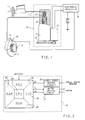
- the vehicle braking apparatus is composed of a hydraulic boost unit 1 and brake lines 2 going to the wheel brake, such as a caliper 3 located at the rotor 4 , of a vehicle wheel.
- the total vehicle braking apparatus is comprised of the standard base braking components and a) an electronic controller 16 , b) a wheel speed sensor 18 mounted at the wheel near c) an excitor ring 19 , and d) a modulator assembly 10 described by the following mechanical relationships: 1) a DC motor 12 drives a gear train 24 , turning a ball screw actuator 14 , which is composed of a linear ball screw and nut; 2) as the linear ball screw rotates, the nut is moved either forward or backward; 3) when the DC motor drives the linear ball screw in the apply direction, the nut moves forward and a piston 22 is applied toward the top of travel; 4) a check ball 20 is unseated and held open when the piston 22 is at the top of travel; 5) when the
- the wheel lock control apparatus in this embodiment is operative at all times while the vehicle is in operation. As the vehicle wheel rotates, the excitor ring 19 rotates, causing the wheel speed sensor 18 to generate a signal proportional to the wheel speed. The signal is sent from the wheel speed sensor 18 to the electronic controller 16 for processing.
- the ball screw actuator 14 as shown in Figure 1, is in the passive mode with the check ball 20 held open by the piston 22 at the top of travel. When the driver of the vehicle applies the brakes, with antilock passive, the hydraulic fluid can pass through the brake line 2 past the check ball 20 and through to the wheel brake caliper 3 . Thus the wheel lock control apparatus is said to be transparent during normal braking.
- the wheel lock control apparatus detects incipient wheel lockup based upon the parameters of vehicle wheel slip and wheel deceleration.
- the information from the wheel speed sensor 18 is used by the electronic controller 16 to calculate wheel slip and acceleration.
- the electronic controller 16 Upon detecting high wheel slip or deceleration, indicative of an incipient wheel lock condition, the electronic controller 16 initiates antilock activity.
- the electronic controller 16 commands the DC motor 12 to reverse the ball screw actuator 14 , causing the piston 22 to retract and the check ball 20 to seat, isolating the hydraulic boost unit 1 of the hydraulics from the wheel brake. As the piston 22 retracts, pressure at the wheel brake is relieved, allowing the wheel to begin to reaccelerate.
- the electronic controller 16 commands the DC motor 12 to hold pressure constant, which halts the motion of the piston 22 and allows motor torque and wheel brake pressure to remain equalized.
- the electronic controller 16 commands the DC motor 12 to reapply pressure, causing the ball screw actuator 14 to move forward, applying the piston 22 and returning fluid back to the wheel brake caliper 3 .
- Wheel brake pressure is then increased toward the optimal pressure for the road surface.
- a wheel cycle is defined as beginning with the detection of incipient lock and the subsequent release of pressure and ending when the pressure has been reapplied to the point just prior to incipient lock.
- the electronic controller 16 Based on the stated relationship between motor current, I, and wheel brake pressure, P, the electronic controller 16 implements instructions to achieve the desired wheel brake pressure. As shown in figure 2 , the electronic controller 16 consists of a) a common digital computer composed of read-only memory (ROM) 25 , random access memory (RAM) 26 , a power supply device (PSD) 28 , an instruction processing architecture embodied in a central processing unit (CPU) 29 , and input/output circuitry (I/O) 30 which interface to a b) motor driver circuit 31 and c) wheel speed sensor buffer circuit 32 .
- ROM read-only memory
- RAM random access memory
- PSD power supply device
- I/O input/output circuitry
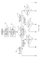
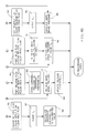
- the ROM 25 contains the instructions necessary to implement the algorithm diagrammed in figures 3 and 4. It should be noted that in describing the functions of the algorithm encoded in the ROM 25 , references to tasks which have been detailed as flow diagram function blocks will be designated by ⁇ nn> , where nn is the diagram reference number and ⁇ > indicates that the concept described by the particular flow diagram function block text is being referenced.
- the text in the flow diagram function block is intended to describe the general task or process being executed by the electronic controller 16 at that point. The text does not represent the actual ROM instructions. It is recognized that there are a variety of known information-processing languages available to one skilled in the art to construct the actual instructions necessary to accomplish the tasks described by the text in the flow diagram function blocks.
- the electronic controller 16 When the wheel lock control apparatus is powered-up, via the vehicle ignition or other means, the electronic controller 16 will begin executing the instructions coded in ROM 25 . As shown in figure 3, the electronic controller 16 will first perform system initialization ⁇ 35> , which entails clearing registers, initializing specific RAM variables to calibrated values, stabilizing voltage levels at the I/O and other basic functions of the digital computer.
- the system initialization process also includes insuring the ball screw actuator 14 is in the passive, or as earlier described, the transparent, mode shown in figure 1.
- the ball screw actuator 14 is said to be transparent to the base braking functionality of the vehicle while the check ball 20 is unseated and is held open by the piston 22 , allowing hydraulic boost unit 1 to reach the wheel brake.
- the electronic controller 16 will enable the control cycle interrupt ⁇ 36> .
- the control cycle interrupt provides a means for accurately calculating the critical vehicle parameters of wheel slip and acceleration by insuring that the time between calculations is fixed at a value such as 5 msec.
- the electronic controller 16 proceeds through the major loop referred to as the "control cycle".
- the electronic controller 16 performs both brake control processing tasks ⁇ 38> and background tasks ⁇ 39> .
- the brake control processing tasks include: reading and processing the wheel speed and DC motor signal information, determining whether antilock control is necessary, and performing antilock control functions as needed. Whether or not antilock control is required, the electronic controller 16 always evaluates wheel speed and motor signal information.
- the electronic controller 16 After executing the brake control processing tasks, the electronic controller 16 proceeds to the background tasks ⁇ 39> .
- the background tasks consist of diagnostic self-check activities and communication with off-board devices such as other vehicle controllers or service tools. All of these control cycle tasks are performed once every control cycle interrupt.
- the electronic controller 16 executes the brake control processing tasks ⁇ 38> and background tasks ⁇ 39> . Thus, every control cycle, the electronic controller 16 evaluates the need for antilock activities, performs these activities as needed, and carries out diagnostic and off-board communications activities.
- figure 5 diagrams the resultant wheel brake pressure produced by the wheel lock control apparatus.
- the electronic controller 16 is operative at all times, and executes the instructions, encoded in ROM, within the confines of the control cycle interrupt.
- the electronic controller 16 upon receiving a control cycle interrupt, proceeds to read the wheel speed sensor information ⁇ 50> and calculate the critical parameters of wheel slip and acceleration ⁇ ⁇ 51> .
- the electronic controller 16 subsequently clears the release, hold and reapply flags ⁇ 55> , clears the release duration counter, t r ⁇ 57> , and initializes the reference pressure value, P m , to a calibrated value ⁇ 58> .
- the electronic controller 16 continues the control cycle, proceeding to the background tasks. Since no antilock activities were initiated, the ball screw actuator 14 remains in the transparent mode. Given that the driver of the vehicle continues to apply the brakes, wheel brake pressure increases toward, and soon surpasses, the ideal pressure for the road surface. This phenomenon is depicted in figure 5 by pressure 42 which is greater than pressure level 41 .
- the electronic controller 16 again reads the wheel speed information ⁇ 50> , calculates wheel slip and acceleration ⁇ 51> , and evaluates the status of the critical parameters ⁇ 52> . At this point, the critical parameters indicate an incipient lock condition ⁇ 60> . Having determined to initiate antilock activities, the electronic controller 16 first evaluates the status of the release flag ⁇ 62> , which, based upon the prior control cycle activity, is clear. Note that whenever the release flag is clear, it is indicating that the wheel lock control apparatus was not performing a release during the prior control cycle.
- the electronic controller 16 stores the most recent commanded pressure, P m , which is the reference pressure ⁇ 66> .
- P m is the maximum wheel brake pressure achieved during the wheel cycle, and represents the pressure required to produce incipient wheel lock. Due to the mechanical relationships previously related, the wheel brake pressure P while increasing and/or holding pressure is proportional to the motor current I.
- the motor current draw, I s as sensed by the electronic controller 16 through the motor driver circuit 31 , can be considered representative of actual wheel brake pressure, P m , and is stored as such.
- the ball screw actuator 14 is in the transparent mode prior to initiating antilock activities. Due to this feature, a calibrated value has been stored as P m for this first wheel cycle. The calibrated value for P m was established during the previous control cycle when antilock control activity was not required (flow diagram path ⁇ 52> - ⁇ 53> - ⁇ 55> - ⁇ 57> - ⁇ 58> ). During later wheel cycles, that is, after the initiation of antilock activities, the ball screw actuator 14 is no longer transparent. Referring to the earlier description of the modulator assembly 10 , the DC motor 12 will now be driving the ball screw actuator 14 . Thus the actual value of I s , rather than a calibrated value, is stored in P m during later wheel cycles.
- the electronic controller 16 commands the ball screw actuator 14 to release wheel brake pressure ⁇ 68> . This is accomplished by rotating the DC motor 12 in the reverse direction, which retracts the piston 22 , seats the check ball 20 , isolates the wheel brake from the hydraulic boost unit 1 and relieves pressure at the wheel brake. The resulting release of wheel brake pressure is diagrammed in figure 5 as the decreasing pressure rate 43 .
- the wheel lock control apparatus checks the incipient lock condition and allows the wheel to begin reaccelerating.
- the electronic controller 16 also begins timing the duration of the release, thereby updating the release duration counter, t r ⁇ 69> .
- the electronic controller 16 completes the control cycle by proceeding to execute the background tasks.
- the electronic controller 16 continues to read wheel speed information ⁇ 50> , calculate critical wheel parameters ⁇ 51> , and evaluate the status of the critical parameters ⁇ 52> every interrupt control cycle. While the wheel is still tending to lock ⁇ 60> , the release flag remains set (as it was set during the first time through this path) and the electronic controller 16 proceeds from determining the status of the release flag ⁇ 62> directly to relieving wheel brake pressure ⁇ 68> . It should be noted that while releasing pressure, the mechanical relationship between motor current, I, and wheel brake pressure, P, does not hold true. Thus, the stored value of P m is not disturbed. The electronic controller 16 continues to update the release duration counter, t r ⁇ 69> .
- the electronic controller 16 again reads the wheel speed information ⁇ 50> , calculates ⁇ 51> and evaluates ⁇ 52> the critical wheel parameters, and determines that the wheel is indeed approaching recovery ⁇ 70> .
- this condition can be broadly characterized by a high reacceleration and/or wheel slip decreasing to a value that is nominally above the critical slip value. Proceeding along this flow path, the electronic controller 16 first evaluates the status of the hold flag ⁇ 72> . Given that the wheel lock control apparatus was not performing a hold during the previous control cycle, the flag will be clear ⁇ 72> .
- the hold flag is set and the release and reapply flags are cleared ⁇ 74> .
- (t max - t r ) * P m estimates the amount of pressure remaining at the wheel brake.
- the compliance factoring term, F compliance allows for the compensation of wheel brake compliance, and can be set to a variety of values. In this embodiment, which utilizes a caliper 3 wheel brake, the value can be set to approximately 50%.
- the calculated hold pressure, P h utilizing a compliance factor of 50%, would yield a value between 50% and 0% of the reference pressure.
- the DC motor 12 is commanded to generate the torque necessary to produce and maintain P h ⁇ 78> .
- the resultant wheel brake pressure is depicted as pressure level 44 on figure 4 .
- the wheel brake pressure would fall to level 47 .
- the hold pressure P h the wheel is allowed to continue reaccelerating and approaching recovery, without unnecessarily releasing pressure.
- the electronic controller 16 proceeds, as usual, through steps ⁇ 50> , ⁇ 51> and ⁇ 52> , and determines that the critical parameters indicate the wheel is now substantially recovered ⁇ 80> . This condition is typified by having wheel slip below the critical slip value.
- the electronic controller 16 next evaluates the status of the reapply flag ⁇ 82> , which, based upon the prior control cycle activity, is clear. Keeping with the purpose of the reapply, hold and release flags, the reapply flag is set and the hold and release flags are cleared ⁇ 84> .
- the release duration counter, t r is also cleared ⁇ 86> to indicate a release is no longer in progress. Since the wheel has recovered, pressure can be reapplied to the wheel brake ⁇ 88> .
- the electronic controller 16 initiates the reapply by commanding the DC motor 12 to produce the torque necessary to achieve a significant fraction of the previously stored reference pressure, P m . As related during the background discussion, braking efficiency is maximized by striving to brake at or near the pressure required to produce critical wheel slip. The initial reapply begins from the hold pressure 44 and proceeds rapidly to a significant fraction of P m .
- the electronic controller 16 proceeds along the flow path ⁇ 50> - ⁇ 51> - ⁇ 52> - ⁇ 80> - ⁇ 82> directly to ⁇ 88> , as the reapply flag has been set.
- the motor torque increases slowly, which gradually increases pressure.
- the characteristic of the reapply is shown in figure 5 as pressure profile 45 . After pressure has been substantially increased, the wheel will cease to recover and begin to approach lock, repeating the wheel cycle process.
Landscapes
- Engineering & Computer Science (AREA)
- Physics & Mathematics (AREA)
- Fluid Mechanics (AREA)
- Transportation (AREA)
- Mechanical Engineering (AREA)
- Microelectronics & Electronic Packaging (AREA)
- Regulating Braking Force (AREA)
- Braking Systems And Boosters (AREA)
Applications Claiming Priority (2)
| Application Number | Priority Date | Filing Date | Title |
|---|---|---|---|
| US322138 | 1989-03-13 | ||
| US07/322,138 US4917445A (en) | 1989-03-13 | 1989-03-13 | ABS variant nominal hold pressure |
Publications (3)
| Publication Number | Publication Date |
|---|---|
| EP0388035A2 true EP0388035A2 (fr) | 1990-09-19 |
| EP0388035A3 EP0388035A3 (fr) | 1992-03-11 |
| EP0388035B1 EP0388035B1 (fr) | 1994-05-04 |
Family
ID=23253603
Family Applications (1)
| Application Number | Title | Priority Date | Filing Date |
|---|---|---|---|
| EP90301950A Expired - Lifetime EP0388035B1 (fr) | 1989-03-13 | 1990-02-23 | Appareil de commande de blocage de roue |
Country Status (5)
| Country | Link |
|---|---|
| US (1) | US4917445A (fr) |
| EP (1) | EP0388035B1 (fr) |
| JP (1) | JPH0790764B2 (fr) |
| CA (1) | CA2008777C (fr) |
| DE (1) | DE69008595T2 (fr) |
Cited By (1)
| Publication number | Priority date | Publication date | Assignee | Title |
|---|---|---|---|---|
| EP0678431A3 (fr) * | 1991-10-08 | 1995-11-08 | Honda Motor Co Ltd |
Families Citing this family (23)
| Publication number | Priority date | Publication date | Assignee | Title |
|---|---|---|---|---|
| US5029950A (en) * | 1989-06-26 | 1991-07-09 | General Motors Corporation | Anti-lock braking and traction control system |
| US4986614A (en) * | 1989-08-10 | 1991-01-22 | General Motors Corporation | Motor-driven antilock brake pressure modulator having differential motor performance characteristics |
| US5236257A (en) * | 1990-03-20 | 1993-08-17 | Toyota Jidosha Kabushiki Kaisha | Brake pressure generator having means for controlling pressure independent of operation of brake operating member |
| US5147115A (en) * | 1990-04-16 | 1992-09-15 | General Motors Corporation | Adaptive release apply algorithm |
| US5000524A (en) * | 1990-05-03 | 1991-03-19 | General Motors Corporation | Motor-driven anti-lock brake system having auxiliary field winding |
| US5184299A (en) * | 1990-05-31 | 1993-02-02 | General Motors Corporation | Antilock brake system motor speed control |
| US5102207A (en) * | 1990-12-03 | 1992-04-07 | General Motors Corporation | Antilock brake system with motor current control of the pressure modulator |
| US5163743A (en) * | 1991-12-16 | 1992-11-17 | General Motors Corporation | Antilock brake control which induces rear brake lockup upon front brake lockup |
| US5264767A (en) * | 1992-01-21 | 1993-11-23 | General Motors Corporation | Electro-hydraulic control apparatus for improved hydraulic pressure control |
| US5281009A (en) * | 1992-08-19 | 1994-01-25 | General Motors Corporation | Antilock brake system with closed loop control of hold during release |
| US5273349A (en) * | 1992-08-19 | 1993-12-28 | General Motors Corporation | Antilock brake system with motor current control |
| US5219214A (en) * | 1992-08-28 | 1993-06-15 | General Motors Corporation | Anti-lock brake system permanent magnet motor having differential performance characteristics |
| JPH06286599A (ja) * | 1993-03-31 | 1994-10-11 | Toyota Motor Corp | 車両用ブレーキ圧制御装置 |
| DE4342918A1 (de) * | 1993-12-16 | 1995-06-22 | Bosch Gmbh Robert | Bremsanlage mit Blockierschutzeinrichtung für ein Straßenfahrzeug, insbesondere Personenkraftwagen |
| US5696677A (en) * | 1995-03-27 | 1997-12-09 | General Motors Corporation | Vehicle chassis control |
| US5646848A (en) * | 1995-08-09 | 1997-07-08 | General Motors Corporation | Method for proportionally controlling the brakes of a vehicle based on tire deformation |
| US5646849A (en) * | 1995-08-09 | 1997-07-08 | General Motors Corporation | Method for proportionally controlling the brakes of a vehicle based on front and rear wheel speeds |
| US5511859A (en) * | 1995-08-25 | 1996-04-30 | General Motors Corporation | Regenerative and friction brake blend control |
| US6513886B1 (en) | 1996-05-07 | 2003-02-04 | General Motors Corporation | Brake system control in which update of wheel speed normalization factors is selectively inhibited |
| GB2376992B (en) * | 2001-05-18 | 2005-03-23 | Bamford Excavators Ltd | Vehicle |
| JP4367051B2 (ja) * | 2003-08-25 | 2009-11-18 | 株式会社アドヴィックス | 電気ブレーキシステム |
| WO2009089551A2 (fr) * | 2008-01-11 | 2009-07-16 | General Atomics | Système de freinage à actionneur linéaire |
| KR101734041B1 (ko) * | 2015-11-09 | 2017-05-24 | 주식회사 만도 | 압력 제어 장치 및 그 압력 제어 방법 |
Family Cites Families (10)
| Publication number | Priority date | Publication date | Assignee | Title |
|---|---|---|---|---|
| US3674318A (en) * | 1970-11-18 | 1972-07-04 | Bendix Corp | Anti-skid braking system utilizing pressure feedback |
| US3953083A (en) * | 1974-12-09 | 1976-04-27 | The Bendix Corporation | Duty cycle translator for adaptive braking control circuit |
| US4111497A (en) * | 1977-06-16 | 1978-09-05 | The Bendix Corporation | Pressure command generator with initial condition logic for adaptive braking system |
| IT1098223B (it) * | 1977-08-10 | 1985-09-07 | Girling Ltd | Sistema di controllo antislittamento dei freni |
| DE3435870A1 (de) * | 1984-09-29 | 1986-04-10 | Robert Bosch Gmbh, 7000 Stuttgart | Antiblockierregelsystem |
| US4741580A (en) * | 1985-08-02 | 1988-05-03 | Akebono Brake Industry Co., Ltd. | Anti-skid control system for motor vehicle |
| US4664453A (en) * | 1985-10-21 | 1987-05-12 | General Motors Corporation | Anti-lock brake control system |
| DE3760861D1 (en) * | 1986-01-31 | 1989-11-30 | Nippon Denso Co | Hydraulic pressure control system for motor vehicles |
| US4755945A (en) * | 1986-09-24 | 1988-07-05 | General Motors Corporation | Adaptive mode anti-lock brake controller |
| GB8715129D0 (en) * | 1987-06-27 | 1987-08-05 | Lucas Ind Plc | Hydraulic anti-skid vehicle braking system |
-
1989
- 1989-03-13 US US07/322,138 patent/US4917445A/en not_active Expired - Lifetime
-
1990
- 1990-01-29 CA CA002008777A patent/CA2008777C/fr not_active Expired - Fee Related
- 1990-02-23 DE DE69008595T patent/DE69008595T2/de not_active Expired - Fee Related
- 1990-02-23 EP EP90301950A patent/EP0388035B1/fr not_active Expired - Lifetime
- 1990-03-13 JP JP2062453A patent/JPH0790764B2/ja not_active Expired - Lifetime
Cited By (3)
| Publication number | Priority date | Publication date | Assignee | Title |
|---|---|---|---|---|
| EP0678431A3 (fr) * | 1991-10-08 | 1995-11-08 | Honda Motor Co Ltd | |
| US5573313A (en) * | 1991-10-08 | 1996-11-12 | Honda Giken Kogyo Kabushiki Kaisha | Method of and system for controlling brakes |
| US5577816A (en) * | 1991-10-08 | 1996-11-26 | Honda Giken Kogyo Kabushiki Kaisha | Method of and system for controlling brakes |
Also Published As
| Publication number | Publication date |
|---|---|
| US4917445A (en) | 1990-04-17 |
| CA2008777A1 (fr) | 1990-09-13 |
| CA2008777C (fr) | 1994-05-31 |
| JPH0790764B2 (ja) | 1995-10-04 |
| EP0388035A3 (fr) | 1992-03-11 |
| DE69008595D1 (de) | 1994-06-09 |
| JPH02274650A (ja) | 1990-11-08 |
| DE69008595T2 (de) | 1994-08-18 |
| EP0388035B1 (fr) | 1994-05-04 |
Similar Documents
| Publication | Publication Date | Title |
|---|---|---|
| EP0388035B1 (fr) | Appareil de commande de blocage de roue | |
| EP0380882B1 (fr) | Commande de freinage à antiblocage | |
| EP0392686A2 (fr) | Dispositif et méthode de commande antiblocage | |
| CA2039808C (fr) | Limiteur de lacet sur frein antiblocage | |
| EP0397328B1 (fr) | Appareil et procédé de commande d'entraînement de véhicule | |
| US4750124A (en) | Anti-lock brake control system | |
| JPH04262952A (ja) | アンチロック制御又はトラクション滑り制御に使用する回路 | |
| EP0448145A2 (fr) | Méthode pour commander la vitesse d'un moteur | |
| EP0397330A2 (fr) | Procédé de commande d'entraînement de véhicule | |
| KR0159026B1 (ko) | 앤티-스키드 제어장치 | |
| JPS62191261A (ja) | 車輪ロツク制御装置 | |
| US6466857B1 (en) | Drive wheel traction control during vehicle stability enhancement events | |
| US5071199A (en) | Antilock brake system with motor current control | |
| EP0489451B1 (fr) | Système de réglage antiblocage avec un moyen de commande du courant du moteur | |
| US5315518A (en) | Method and apparatus for initializing antilock brake control on split coefficient surface | |
| US6161907A (en) | Brake control using proportional plus integral slip regulation and proportional pressure regulation | |
| EP0470657B1 (fr) | Procédé de commande de freinage à antiblocage à commande de relâchement pas à pas | |
| US4755946A (en) | Motor actuated anti-lock brake control system | |
| US5308153A (en) | Antilock brake system with closed loop apply bump | |
| EP0459548B1 (fr) | Méthode et appareil pour commander la pression de freinage appliquée à un frein de véhicule | |
| JP3040018B2 (ja) | ブレーキ制御方法 | |
| CN117698727A (zh) | 一种车辆防滑控制方法、系统、终端及存储介质 | |
| JP2600261B2 (ja) | 車両の制動制御装置 | |
| JPH10329683A (ja) | 制動力配分制御方法 | |
| JPS6116163A (ja) | 車輪の空転制御装置 |
Legal Events
| Date | Code | Title | Description |
|---|---|---|---|
| PUAI | Public reference made under article 153(3) epc to a published international application that has entered the european phase |
Free format text: ORIGINAL CODE: 0009012 |
|
| AK | Designated contracting states |
Kind code of ref document: A2 Designated state(s): DE FR GB IT |
|
| PUAL | Search report despatched |
Free format text: ORIGINAL CODE: 0009013 |
|
| AK | Designated contracting states |
Kind code of ref document: A3 Designated state(s): DE FR GB IT |
|
| 17P | Request for examination filed |
Effective date: 19920430 |
|
| 17Q | First examination report despatched |
Effective date: 19930521 |
|
| GRAA | (expected) grant |
Free format text: ORIGINAL CODE: 0009210 |
|
| ITF | It: translation for a ep patent filed | ||
| AK | Designated contracting states |
Kind code of ref document: B1 Designated state(s): DE FR GB IT |
|
| REF | Corresponds to: |
Ref document number: 69008595 Country of ref document: DE Date of ref document: 19940609 |
|
| ET | Fr: translation filed | ||
| PLBE | No opposition filed within time limit |
Free format text: ORIGINAL CODE: 0009261 |
|
| STAA | Information on the status of an ep patent application or granted ep patent |
Free format text: STATUS: NO OPPOSITION FILED WITHIN TIME LIMIT |
|
| 26N | No opposition filed | ||
| PGFP | Annual fee paid to national office [announced via postgrant information from national office to epo] |
Ref country code: GB Payment date: 19970127 Year of fee payment: 8 |
|
| PGFP | Annual fee paid to national office [announced via postgrant information from national office to epo] |
Ref country code: FR Payment date: 19970227 Year of fee payment: 8 |
|
| PGFP | Annual fee paid to national office [announced via postgrant information from national office to epo] |
Ref country code: DE Payment date: 19970411 Year of fee payment: 8 |
|
| PG25 | Lapsed in a contracting state [announced via postgrant information from national office to epo] |
Ref country code: GB Free format text: LAPSE BECAUSE OF NON-PAYMENT OF DUE FEES Effective date: 19980223 |
|
| PG25 | Lapsed in a contracting state [announced via postgrant information from national office to epo] |
Ref country code: FR Free format text: THE PATENT HAS BEEN ANNULLED BY A DECISION OF A NATIONAL AUTHORITY Effective date: 19980228 |
|
| GBPC | Gb: european patent ceased through non-payment of renewal fee |
Effective date: 19980223 |
|
| PG25 | Lapsed in a contracting state [announced via postgrant information from national office to epo] |
Ref country code: DE Free format text: LAPSE BECAUSE OF NON-PAYMENT OF DUE FEES Effective date: 19981103 |
|
| REG | Reference to a national code |
Ref country code: FR Ref legal event code: ST |
|
| PG25 | Lapsed in a contracting state [announced via postgrant information from national office to epo] |
Ref country code: IT Free format text: LAPSE BECAUSE OF NON-PAYMENT OF DUE FEES;WARNING: LAPSES OF ITALIAN PATENTS WITH EFFECTIVE DATE BEFORE 2007 MAY HAVE OCCURRED AT ANY TIME BEFORE 2007. THE CORRECT EFFECTIVE DATE MAY BE DIFFERENT FROM THE ONE RECORDED. Effective date: 20050223 |