EP0394171A2 - Gleitkommaprozessor mit zur Multiplikation und Division voreingestellter Abweichung des Exponenten - Google Patents
Gleitkommaprozessor mit zur Multiplikation und Division voreingestellter Abweichung des Exponenten Download PDFInfo
- Publication number
- EP0394171A2 EP0394171A2 EP90480048A EP90480048A EP0394171A2 EP 0394171 A2 EP0394171 A2 EP 0394171A2 EP 90480048 A EP90480048 A EP 90480048A EP 90480048 A EP90480048 A EP 90480048A EP 0394171 A2 EP0394171 A2 EP 0394171A2
- Authority
- EP
- European Patent Office
- Prior art keywords
- exponent
- bias
- register
- processor
- operand
- Prior art date
- Legal status (The legal status is an assumption and is not a legal conclusion. Google has not performed a legal analysis and makes no representation as to the accuracy of the status listed.)
- Withdrawn
Links
Images


Classifications
-
- G—PHYSICS
- G06—COMPUTING OR CALCULATING; COUNTING
- G06F—ELECTRIC DIGITAL DATA PROCESSING
- G06F7/00—Methods or arrangements for processing data by operating upon the order or content of the data handled
- G06F7/38—Methods or arrangements for performing computations using exclusively denominational number representation, e.g. using binary, ternary, decimal representation
- G06F7/48—Methods or arrangements for performing computations using exclusively denominational number representation, e.g. using binary, ternary, decimal representation using non-contact-making devices, e.g. tube, solid state device; using unspecified devices
- G06F7/483—Computations with numbers represented by a non-linear combination of denominational numbers, e.g. rational numbers, logarithmic number system or floating-point numbers
- G06F7/487—Multiplying; Dividing
- G06F7/4876—Multiplying
-
- G—PHYSICS
- G06—COMPUTING OR CALCULATING; COUNTING
- G06F—ELECTRIC DIGITAL DATA PROCESSING
- G06F7/00—Methods or arrangements for processing data by operating upon the order or content of the data handled
- G06F7/38—Methods or arrangements for performing computations using exclusively denominational number representation, e.g. using binary, ternary, decimal representation
- G06F7/48—Methods or arrangements for performing computations using exclusively denominational number representation, e.g. using binary, ternary, decimal representation using non-contact-making devices, e.g. tube, solid state device; using unspecified devices
- G06F7/52—Multiplying; Dividing
- G06F7/535—Dividing only
-
- G—PHYSICS
- G06—COMPUTING OR CALCULATING; COUNTING
- G06F—ELECTRIC DIGITAL DATA PROCESSING
- G06F7/00—Methods or arrangements for processing data by operating upon the order or content of the data handled
- G06F7/38—Methods or arrangements for performing computations using exclusively denominational number representation, e.g. using binary, ternary, decimal representation
- G06F7/48—Methods or arrangements for performing computations using exclusively denominational number representation, e.g. using binary, ternary, decimal representation using non-contact-making devices, e.g. tube, solid state device; using unspecified devices
- G06F7/52—Multiplying; Dividing
- G06F7/535—Dividing only
- G06F7/537—Reduction of the number of iteration steps or stages, e.g. using the Sweeny-Robertson-Tocher [SRT] algorithm
- G06F7/5375—Non restoring calculation, where each digit is either negative, zero or positive, e.g. SRT
-
- G—PHYSICS
- G06—COMPUTING OR CALCULATING; COUNTING
- G06F—ELECTRIC DIGITAL DATA PROCESSING
- G06F7/00—Methods or arrangements for processing data by operating upon the order or content of the data handled
- G06F7/38—Methods or arrangements for performing computations using exclusively denominational number representation, e.g. using binary, ternary, decimal representation
- G06F7/48—Methods or arrangements for performing computations using exclusively denominational number representation, e.g. using binary, ternary, decimal representation using non-contact-making devices, e.g. tube, solid state device; using unspecified devices
- G06F7/483—Computations with numbers represented by a non-linear combination of denominational numbers, e.g. rational numbers, logarithmic number system or floating-point numbers
- G06F7/487—Multiplying; Dividing
- G06F7/4873—Dividing
-
- G—PHYSICS
- G06—COMPUTING OR CALCULATING; COUNTING
- G06F—ELECTRIC DIGITAL DATA PROCESSING
- G06F7/00—Methods or arrangements for processing data by operating upon the order or content of the data handled
- G06F7/38—Methods or arrangements for performing computations using exclusively denominational number representation, e.g. using binary, ternary, decimal representation
- G06F7/48—Methods or arrangements for performing computations using exclusively denominational number representation, e.g. using binary, ternary, decimal representation using non-contact-making devices, e.g. tube, solid state device; using unspecified devices
- G06F7/499—Denomination or exception handling, e.g. rounding or overflow
- G06F7/49905—Exception handling
- G06F7/4991—Overflow or underflow
-
- G—PHYSICS
- G06—COMPUTING OR CALCULATING; COUNTING
- G06F—ELECTRIC DIGITAL DATA PROCESSING
- G06F7/00—Methods or arrangements for processing data by operating upon the order or content of the data handled
- G06F7/38—Methods or arrangements for performing computations using exclusively denominational number representation, e.g. using binary, ternary, decimal representation
- G06F7/48—Methods or arrangements for performing computations using exclusively denominational number representation, e.g. using binary, ternary, decimal representation using non-contact-making devices, e.g. tube, solid state device; using unspecified devices
- G06F7/499—Denomination or exception handling, e.g. rounding or overflow
- G06F7/49936—Normalisation mentioned as feature only
-
- G—PHYSICS
- G06—COMPUTING OR CALCULATING; COUNTING
- G06F—ELECTRIC DIGITAL DATA PROCESSING
- G06F7/00—Methods or arrangements for processing data by operating upon the order or content of the data handled
- G06F7/38—Methods or arrangements for performing computations using exclusively denominational number representation, e.g. using binary, ternary, decimal representation
- G06F7/48—Methods or arrangements for performing computations using exclusively denominational number representation, e.g. using binary, ternary, decimal representation using non-contact-making devices, e.g. tube, solid state device; using unspecified devices
- G06F7/499—Denomination or exception handling, e.g. rounding or overflow
- G06F7/49942—Significance control
- G06F7/49947—Rounding
Definitions
- the present invention relates to electronic data processing, and more particularly concerns a floating-point processor whose operands have exponent parts are offset from their true values by a fixed bias.
- Floating-point numbers are stored in computers as a fraction (or mantissa) part and an exponent part. Fractions most often have an associated sign bit to indicate whether the fraction is positive or negative. Exponents, on the other hand, are commonly represented as positive numbers only, even though the actual exponent value can be negative as well as positive. This is accomplished by adding a bias value to the true exponent value. For example, an 8-bit exponent field can represent actual exponent values of -126 to +127 by adding a bias of 127, yielding stored values +2 to +253. (The stored values 0, 1, 254, and 255 signify error conditions).
- Biased exponents however, have a disadvantage for multiplication and division operations. Since the operand exponents must be added together for multiplication, the exponent of the result contains twice the bias, and another operation is required to subtract out the extra bias amount. In division, the operand exponents are subtracted; the result exponent then has no bias, and another operation is required to add the bias back in.
- bias adjustments for multiplication and division have been performed with another trip through the same arithmetic unit used for adding or subtracting the operand exponents.
- a multiplication operation may add the operand exponents from two registers in a first clock cycle, and store the sum in one of the registers.
- the sum and a constant bias value are gated through the same adder, and stored again in one of the registers.
- Another technique is to provide two cascaded arithmetic units, which requires a slower cycle time to accommodate the longer data paths.
- the present invention preserves the advantages of a biased-exponent floating-point processor by substantially eliminating the time and/or hardware penalties incurred during multiplication and division operations with this exponent representation.
- the invention is able to adjust an exponent for a bias value with extremely little added hardware.
- the very small amount of additional delay appears only in the bias-adjustment path, and does not affect any other operations.
- the result exponent is available in a single cycle of the processor.
- No arithmetic addition operation is required in order to add or subtract the bias value during a multiply or divide operation.
- the maximum data width is not increased; it does not exceed that already required for the operand exponents and the conventional overflow and underflow bits.
- the invention is an exponent unit for a floating-point processor including bias-adjustment logic in the data path between one of the operand exponent registers and the exponent adder.
- This logic is a simple combinatorial logic which operates only on the higher-order bits of one operand to perform an operation which is equivalent to an addition or subtraction of the bias quantity, either alone or in combination with the conventional exponent adder.
- the same exponent unit, including the same combinatorial logic can handle different precision levels or formats of operands.
- FIG. 1 shows a portion of a data-processing system 100 which may serve as an environment for the invention.
- Processor bus 110 inter-connects a main processor 120, a floating-point coprocessor 130, and a main storage unit 140.
- the conventional bus 110 has parallel lines 111 for control, lines 112 for addresses, and lines 113 for data.
- coprocessor 130 does not drive the address lines 112.
- Main processor 120 controls the fetching of the operands it requires from main storage 140, and the storage of its results, via data lines 113.
- a conventional microcode control unit 150 controls both of the processors 120 and 130.
- Unit 150 stores horizontal microcode words, each of which has fields for gating data paths, specifying operations, and so forth; these are transmitted over lines 151 to both of the processors. (Although not necessary to the invention, some of the fields could specify one action to main processor 120, and a different action to coprocessor 130. Another bit or field in the word determines which action is to be executed).
- Each word also contains the address of the next microcode word to be executed. This address can be modified by certain conditions occurring in the processors; these conditions are transmitted to unit 150 over lines 152 and 153.
- Clock 160 drives unit 150 to fetch a new microcode word every cycle.
- the blocks thus far described connect to other units, such as workstation adapters, bulk storage drives, and other input/output devices (not shown) to form a complete data-processing system. These connections may occur via bus 110 or by means of another bus or channel (not shown) attached to main processor 120.
- FIG. 2 illustrates a much simplified example of an exponent subunit 200 according to the prior art, for a coprocessor such as 130, Fig. 1.
- Register 210 receives a first operand OP1 via selector (or gate, or multiplexer) 211 directly or indirectly from data lines 113.
- Register 220 receives a second operand OP2 via selector 221.
- An exponent adder 230 has one input controlled by selector 231 and another input controlled by selector 232.
- Microword control lines 151 gate one of five inputs of selector 231 into the adder, according to whether the operands are single or double precision (S/D), and whether the operation requested by the current instruction is multiply or divide (M/D).
- the M/D bit also determines whether adder 230 will add or subtract its two inputs.
- Selector 232 chooses between the output 222 and another source which is not relevant to the present explanation.
- Lines 222 also connect to data lines 113.
- the output 233 feeds back to selector 221.
- Subunit 200 requires two microcode cycles to produce a result, after the operands have been loaded.
- selectors 231 and 232 feed OP1+BIAS, the contents of register 210, and OP2+BIAS, in register 220, to adder 230, which adds them together.
- Selector 221 gates the adder output 233 back into register 220.
- register 220 holds the intermediate result OP1+OP2+2*BIAS.
- the register and the adder require more stages.
- lines 151 cause selector 231 to gate the negative of the single-precision bias (-BS) into the first adder input, while selector 232 gates the intermediate result to the adder.
- the sum of these two quantities, OP1+OP2+BIAS, is gated back into register 220, and appears at output lines 222.
- the other three constants at selector 231, are used for single-precision division (+BS), and double-precision multiplication (-BD) and division (+BD).
- FIG. 3 shows a floating-point coprocessor 130 according to the invention.
- the various subunits will be characterized in the roles they assume during a multiplication operation; some of the blocks may function differently for other operations.
- Coprocessor 130 operates upon numbers in formats according to Draft 10.1 of the IEEE Task P754 Proposed Standard for Binary Floating-Point Arithmetic.
- the 4-byte single-precision format of this standard calls for a sign bit followed by an 8-bit exponent biased up by 127, followed by a 23-bit mantissa or fraction normalized to a value between (decimal) 1 and 2.
- Valid unbiased exponents range from -125 to +126 (1 to 254 when biased); values of -126 and +127 (0 and 255 when biased) represent underflow and overflow conditions, respectively.
- the 8-byte double-precision format has a sign bit, an 11-bit exponent biased up by 1023, and a 52-bit normalized frac tion. In both formats, denormalized numbers have a biased exponent of binary 1, and at least one leading 0 in the fraction.
- Coprocessor 130 has a transfer unit 300 for moving and storing operands, an exponent unit 310 for manipulating the operand exponents according to a desired operation, and a fraction unit 350 for manipulating operand fractions according to the selected operation. Routing of data through the various paths of coprocessor 130 is controlled by a conventional sequencer 380, which receives one control word per instruction from microcode control unit 150, Fig. 1, over lines 151. Sequencer 380 transmits control signals to the other elements of the coprocessor on lines 381 during a number of cycles.
- Transfer unit 300 receives operands from, and transmits operands to, data lines 113, Fig. 1.
- An instruction which specifies memory operands will read these operands from data lines 113, and may transmit a result directly back to main storage via lines 113.
- Some instructions use a set of local 8-byte wide floating-point registers 301 for storing operands and/or results.
- An internal bus 302 carries operands from their source to the units 310 and 350, and carries results from these units back to a destination, either registers 301 or lines 113.
- Registers 303 and 304 hold data on lines 113.
- Exponent unit 310 receives the exponent fields of a first operand from bus 302 on lines 311.
- Selector or multiplexer 312 gates the bits of this field into FBEXP register 313.
- register 313 receives the biased exponent field of the multiplier, OP1+BIAS.
- Lines 314 transport the biased exponent field OP2+BIAS of a second operand (the multiplicand, in this example) to selector 315 for storage into FAEXP register 316.
- Selectors 312 and 315 like all the selectors in coprocessor 130, are controlled by bits in the microcode words emanating from control unit 150, Fig. 1; for clarity of exposition these lines are not generally shown in Fig. 3.
- Registers 313 and 316 are conventional master/slave registers, which use a two-phase clock signal (not shown) for every microcode cycle.
- the output lines remain latched with the contents of the register, while the input lines receive new data into the register.
- the data on the input lines are latched.
- the latched input data appear at the output lines.
- Exponent adder 317 is a conventional twos-complement carry-propagate adder for combining the exponent fields of the operands to produce a result on line 318.
- the adder adds its two inputs for a multiplication instruction, but subtracts them for division. Addition occurs when lines 319 are gated through selector 321 under the control of an M/D bit in lines 151.
- Register 316 also produces inverted outputs on lines 321. Subtraction occurs when selector 321 gates these ones-complement lines, and low-order carry-in bit Cin is activated by the M/D bit.
- the result 318 is loaded back into register 316 via selector 315.
- Conventional overflow/under-flow detector 322 also receives the result, and produces signals on condition lines 153 for influencing controller 150, Fig. 1.
- Lines 319 also carry the contents of register 316 to internal bus 302 for transfer to the local operand registers or to main storage.
- Selector 322 can receive an output 323 from a normalize/round unit for normalizing the result exponent in a conventional manner. (A preferred normalize/round unit is shown in commonly assigned application, US serial number 07/339,348 (Docket RO 9 89 003)
- Selector 322 may also gate the contents of register 313, after transformation by bias-adjust logic 324, over lines 325.
- Bias-adjust logic 324 adds or subtracts one of two fixed bias amounts (decimal 127 or 1023) with the contents of register 313 on line 326.
- the bias amount depends upon the precision of the operands, carried by S/D line 151; the logic adds the bias for a division and subtracts it for a multiplication, as specified by M/D control line 151.
- the exponent unit 310 performs the operation (OP1EXP+BIAS) + (OP2EXP+BIAS) - BIAS ---> (RESEXP+BIAS) in a single cycle.
- the unit produces (OP1EXP+BIAS) - (OP2EXP+BIAS) BIAS ---> (RESEXP+BIAS) on lines 318 in a single microword cycle. Subtraction is accomplished by ones-complement addition with a carry bit, as described above.
- Logic 324 could be a conventional carry-propagate or other adder circuit. However, the properties of the particular bias amounts in this embodiment allow the use of a considerably simpler and faster circuit.
- the purpose of logic 324 is to modify the quantity (OP1EXP+BIAS) stored in register 313 so that the exponent unit produces the overall result of the above equations.
- the following tables show how this can be accomplished by four combinatorial-logic functions, without performing any arithmetic operations at all in the bias-adjust logic.
- Two 3-input functions of the high-order three bits on lines 326 serve for double-precision multiply and divide; two 6-input functions of the high-order six bits on these lines handle single-precision.
- the symbol 'X' indicates a don't-care bit.
- the symbol '-' indicates that an input combination is not possible.
- the range of valid exponents requires 11-bit binary numbers.
- Unit 130 uses 13-bit operands used for exponents.
- the third high-order bit, Bit(2) is the actual high-order bit of the 11-bit result. Note that some combinations of these three bits are logically impossible.
- Exponent unit 130 uses 13-bit numbers for these as well.
- the high-order bit is still the underflow bit, but the overflow bit is now Bit(4).
- the high-order bit of the actual result is now Bit(5).
- the above functions may easily be realized by a read-only memory array, programmable logic array, or other conventional means having inputs for the six high-order bits and selector lines for multiply-divide and single/double precision, and outputs for the six high-order bits.
- Fraction unit 350 manipulates the fraction or mantissa of the floating-point operands in accordance with the operation selected by the current instruction. This unit is not a part of the present invention, and may function in any convenient manner. The components of unit 350 will be de-scribed using a multiplication operation as an example. Unit 350 employs a recoding algorithm which retires four bits of the multiplier in each microcode cycle.
- FBFRAC register 351 holds intermediate partial products and the final product of a multiplication.
- Microcode control lines gate one of four inputs into register 351 through selector 352.
- Lines 353 carry partial products at the end of each clock cycle.
- Lines 354 can receive the multiplicand operand directly from bus 302.
- Lines 355 receive the final rounded and normalized product.
- the selector can be turned off, so that an all-zero input reaches the register.
- Register output lines 356 return this result to bus 302, and also transmit the partial products to one input of fraction adder 357.
- Shifter 358 connects the output bits of the adder to lines 353 so as to achieve a four-bit shift to the left.
- shifter 358 is merely a displacement in the wiring connections of four bit positions.
- FAFRAC register 361 holds the multiplicand operand, loaded from bus 302 through lines 362 when a microcode word activates selector 363. The output of this register is always presented to multiples generator 364.
- Generator 364 is a conventional combinatorial circuit which produces four simultaneous multiples of the contents of register 361; these multiples are -4, -2, 0, +2, and +4. They are available at the output of a selector 365 for transfer on lines 367 to another input of adder 357. The multiples are also available shifted two bits to the left (i.e., as -16, -4, 0, +4, and +16) at another selector 366, for transfer on lines 368 to a third input of the fraction adder.
- FCFRAC register 371 holds the multiplier operand, gated through selector 372 from lines 373, ultimately from bus 302.
- the output of this register, on lines 374 communicates with aligner 375.
- the aligner shifts the multiplier four bits right after every microcode cycle, then gates the shifted multiplier on lines 376 back into register 371 via selector 372. (Logic gates are used here to achieve the shift, because they are necessary for other operations).
- Lines 376 also connect to detector 377, which senses the presence of large groups of zeros and activates a line 153 to cause aligner 375 to shift over the entire group for the next cycle.
- Recode logic 378 connects to the low-order three bits of register 371, and produces a two-bit output for controlling selector 365 to determine which unshifted multiple from generator is sent to adder 357.
- An identical recode logic 379 connects to the third, fourth, and fifth low-order bits of register 371, and produces a two-bit output for controlling selector 366 to determine which shifted multiple from generator is sent to adder 357.
- Diagrammatically, the recode logics look at the following bits of the multiplier (represented by Xs) during the first two cycles of sequencer 380 :
- Both recoding logics are identical, and may be in the form of a very small read-only storage or logic array. Because of the two-bit left shift into selector 366, the multiple on lines 368 is four times the corresponding multiple on lines 367.
- the mapping of the recoding logics is as follows : Multiplier bits (High,Mid,Low) Unshifted Multiple Shifted Multiple 000 0 0 001 +2 +8 010 +2 +8 011 +4 +16 100 -4 -16 101 -2 -8 110 -2 -8 111 0 0
- multiplicand is initially gated into register 351, via lines 354, at the same time it is gated into register 371 via lines 373. This creates an initial partial product of one times the multiplicand.
- selector 352 is turned off when register 372 initially loads the multiplicand, so that the initial partial product is zero.
- each recoding logic looks at three bits of the multiplier, and both logics together look at five multiplier bits, in order to increase the partial product by an amount represented by four multiplier bits.
- the low-order bit investigated is the same as the high-order bit from the previous cycle.
- Fraction adder 357 adds together three operands simultaneously to produce a single output, which is then left-shifted and returned on lines 353 to partial-product register 351, all in a single clock cycle.
- adder 357 may comprise a conventional carry-save adder not shown) which accepts three inputs (lines 357, 367, and 368) and produces two intermediate outputs.
- a conventional carry-propagate adder (not shown) combines these two intermediate outputs into a final result which, shifted left four places, appears on lines 353.
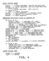
- FIG. 4 shows a sequence of operations for carrying out a complete multiplication operation.
- one or more conventional FETCH control words from controller 150 obtains the operands from main storage or FP registers over bus 302.
- an OPERATION control word starts sequencer 380 at a point appropriate for the multiply operation.
- Sequencer 380 then executes a number of operation cycles.
- each operation cycle processes four bits of the multiplier, so that a single-precision multiply requires six cycles, while a double-precision multiply requires thirteen. (Preferably, large groups of contiguous zeros are skipped in a single cycle by aligner 375; the details of this are not relevant here).
- sequencer 380 may be found in the aforementioned application, US serial number 07/339,285 (Docket RO 9 88 029) concerning "Overlapped Execution”.
Landscapes
- Engineering & Computer Science (AREA)
- Physics & Mathematics (AREA)
- General Physics & Mathematics (AREA)
- Computational Mathematics (AREA)
- Mathematical Analysis (AREA)
- Mathematical Optimization (AREA)
- Pure & Applied Mathematics (AREA)
- Theoretical Computer Science (AREA)
- Computing Systems (AREA)
- General Engineering & Computer Science (AREA)
- Nonlinear Science (AREA)
- Complex Calculations (AREA)
Applications Claiming Priority (2)
| Application Number | Priority Date | Filing Date | Title |
|---|---|---|---|
| US07/339,279 US4975868A (en) | 1989-04-17 | 1989-04-17 | Floating-point processor having pre-adjusted exponent bias for multiplication and division |
| US339279 | 1999-06-23 |
Publications (2)
| Publication Number | Publication Date |
|---|---|
| EP0394171A2 true EP0394171A2 (de) | 1990-10-24 |
| EP0394171A3 EP0394171A3 (de) | 1992-07-01 |
Family
ID=23328284
Family Applications (1)
| Application Number | Title | Priority Date | Filing Date |
|---|---|---|---|
| EP19900480048 Withdrawn EP0394171A3 (de) | 1989-04-17 | 1990-03-13 | Gleitkommaprozessor mit zur Multiplikation und Division voreingestellter Abweichung des Exponenten |
Country Status (3)
| Country | Link |
|---|---|
| US (1) | US4975868A (de) |
| EP (1) | EP0394171A3 (de) |
| JP (1) | JPH07104778B2 (de) |
Cited By (3)
| Publication number | Priority date | Publication date | Assignee | Title |
|---|---|---|---|---|
| EP0602888A1 (de) * | 1992-12-18 | 1994-06-22 | Xerox Corporation | Durchführung aritmetische Operationen auf Daten |
| US5689592A (en) * | 1993-12-22 | 1997-11-18 | Vivo Software, Inc. | Parallel processing of digital signals in a single arithmetic/logic unit |
| US8683182B2 (en) | 1995-08-16 | 2014-03-25 | Microunity Systems Engineering, Inc. | System and apparatus for group floating-point inflate and deflate operations |
Families Citing this family (29)
| Publication number | Priority date | Publication date | Assignee | Title |
|---|---|---|---|---|
| US5153848A (en) * | 1988-06-17 | 1992-10-06 | Bipolar Integrated Technology, Inc. | Floating point processor with internal free-running clock |
| EP0378415A3 (de) * | 1989-01-13 | 1991-09-25 | International Business Machines Corporation | Verteilungsmechanismus für mehrere Befehle |
| US5093908A (en) * | 1989-04-17 | 1992-03-03 | International Business Machines Corporation | Method and apparatus for executing instructions in a single sequential instruction stream in a main processor and a coprocessor |
| DE69132807T2 (de) * | 1990-08-24 | 2002-06-27 | Matsushita Electric Industrial Co., Ltd. | Verfahren und Gerät zur Berechnung von Gleitkommadaten |
| JPH04165530A (ja) * | 1990-10-30 | 1992-06-11 | Nec Corp | 浮動小数点乗算装置 |
| JPH06103599B2 (ja) * | 1990-11-16 | 1994-12-14 | 三菱電機株式会社 | 半導体集積回路装置 |
| US5539684A (en) * | 1993-12-10 | 1996-07-23 | Motorola, Inc. | Method and apparatus for calculating floating point exponent values |
| US5550768A (en) * | 1995-01-31 | 1996-08-27 | International Business Machines Corporation | Rounding normalizer for floating point arithmetic operations |
| US5602769A (en) * | 1995-07-05 | 1997-02-11 | Sun Microsystems, Inc. | Method and apparatus for partially supporting subnormal operands in floating point multiplication |
| US5619439A (en) * | 1995-07-05 | 1997-04-08 | Sun Microsystems, Inc. | Shared hardware for multiply, divide, and square root exponent calculation |
| US5742840A (en) * | 1995-08-16 | 1998-04-21 | Microunity Systems Engineering, Inc. | General purpose, multiple precision parallel operation, programmable media processor |
| US5953241A (en) * | 1995-08-16 | 1999-09-14 | Microunity Engeering Systems, Inc. | Multiplier array processing system with enhanced utilization at lower precision for group multiply and sum instruction |
| US6295599B1 (en) * | 1995-08-16 | 2001-09-25 | Microunity Systems Engineering | System and method for providing a wide operand architecture |
| US7301541B2 (en) | 1995-08-16 | 2007-11-27 | Microunity Systems Engineering, Inc. | Programmable processor and method with wide operations |
| US6006318A (en) * | 1995-08-16 | 1999-12-21 | Microunity Systems Engineering, Inc. | General purpose, dynamic partitioning, programmable media processor |
| KR100425674B1 (ko) * | 1996-10-11 | 2004-06-11 | 엘지전자 주식회사 | 디지탈신호처리기의부동소숫점형식곱셈방법 |
| KR100431707B1 (ko) * | 1996-11-12 | 2004-09-04 | 주식회사 하이닉스반도체 | 부동소수점연산에서의지수처리방법 |
| USH1993H1 (en) * | 1997-06-25 | 2001-09-04 | Sun Microsystems, Inc. | Floating-point division and squareroot circuit with early determination of resultant exponent |
| US6131106A (en) * | 1998-01-30 | 2000-10-10 | Sun Microsystems Inc | System and method for floating-point computation for numbers in delimited floating point representation |
| US20050289208A1 (en) * | 2004-06-23 | 2005-12-29 | Harrison John R | Methods and apparatus for determining quotients |
| US7949695B2 (en) * | 2004-10-27 | 2011-05-24 | Via Technologies Inc. | Two's complement circuit |
| US7698352B2 (en) * | 2005-09-15 | 2010-04-13 | International Business Machines Corporation | System and method for converting from scaled binary coded decimal into decimal floating point |
| US8364734B2 (en) * | 2005-09-15 | 2013-01-29 | International Business Machines Corporation | Converting from decimal floating point into scaled binary coded decimal |
| US20080270495A1 (en) * | 2007-04-26 | 2008-10-30 | International Business Machines Corporation | Insert/extract biased exponent of decimal floating point data |
| US8190664B2 (en) * | 2007-04-26 | 2012-05-29 | International Business Machines Corporation | Employing a mask field of an instruction to encode a sign of a result of the instruction |
| US8051117B2 (en) * | 2007-04-26 | 2011-11-01 | International Business Machines Corporation | Shift significand of decimal floating point data |
| US8051118B2 (en) * | 2007-04-26 | 2011-11-01 | International Business Machines Corporation | Composition of decimal floating point data |
| US9996319B2 (en) * | 2015-12-23 | 2018-06-12 | Intel Corporation | Floating point (FP) add low instructions functional unit |
| US9996320B2 (en) * | 2015-12-23 | 2018-06-12 | Intel Corporation | Fused multiply-add (FMA) low functional unit |
Family Cites Families (8)
| Publication number | Priority date | Publication date | Assignee | Title |
|---|---|---|---|---|
| JPS5330241A (en) * | 1976-09-01 | 1978-03-22 | Hitachi Ltd | Arithmetic unit |
| US4366548A (en) * | 1981-01-02 | 1982-12-28 | Sperry Corporation | Adder for exponent arithmetic |
| US4528640A (en) * | 1982-07-13 | 1985-07-09 | Sperry Corporation | Method and a means for checking normalizing operations in a computer device |
| JPS5968058A (ja) * | 1982-10-13 | 1984-04-17 | Hitachi Ltd | フロ−テイング乗算器 |
| JPS59103148A (ja) * | 1982-12-03 | 1984-06-14 | Hitachi Ltd | 乗算回路 |
| JPS59117637A (ja) * | 1982-12-24 | 1984-07-07 | Toshiba Corp | 浮動小数点乗算装置 |
| JPS6319894A (ja) * | 1986-07-14 | 1988-01-27 | 山崎 忠義 | プリント基板写真焼付方法 |
| US4823260A (en) * | 1987-11-12 | 1989-04-18 | Intel Corporation | Mixed-precision floating point operations from a single instruction opcode |
-
1989
- 1989-04-17 US US07/339,279 patent/US4975868A/en not_active Expired - Fee Related
-
1990
- 1990-03-13 EP EP19900480048 patent/EP0394171A3/de not_active Withdrawn
- 1990-04-03 JP JP2087638A patent/JPH07104778B2/ja not_active Expired - Lifetime
Cited By (5)
| Publication number | Priority date | Publication date | Assignee | Title |
|---|---|---|---|---|
| EP0602888A1 (de) * | 1992-12-18 | 1994-06-22 | Xerox Corporation | Durchführung aritmetische Operationen auf Daten |
| US5408670A (en) * | 1992-12-18 | 1995-04-18 | Xerox Corporation | Performing arithmetic in parallel on composite operands with packed multi-bit components |
| US5689592A (en) * | 1993-12-22 | 1997-11-18 | Vivo Software, Inc. | Parallel processing of digital signals in a single arithmetic/logic unit |
| US8683182B2 (en) | 1995-08-16 | 2014-03-25 | Microunity Systems Engineering, Inc. | System and apparatus for group floating-point inflate and deflate operations |
| US8769248B2 (en) | 1995-08-16 | 2014-07-01 | Microunity Systems Engineering, Inc. | System and apparatus for group floating-point inflate and deflate operations |
Also Published As
| Publication number | Publication date |
|---|---|
| EP0394171A3 (de) | 1992-07-01 |
| JPH02294730A (ja) | 1990-12-05 |
| JPH07104778B2 (ja) | 1995-11-13 |
| US4975868A (en) | 1990-12-04 |
Similar Documents
| Publication | Publication Date | Title |
|---|---|---|
| US4975868A (en) | Floating-point processor having pre-adjusted exponent bias for multiplication and division | |
| US5517438A (en) | Fast multiply-add instruction sequence in a pipeline floating-point processor | |
| US5161117A (en) | Floating point conversion device and method | |
| EP0754998B1 (de) | Rechenwerk | |
| US4694416A (en) | VLSI programmable digital signal processor | |
| KR100242274B1 (ko) | 제산 및 제곱근 계산 기능을 갖고 있는 부동 소숫점/정수 프로세서 | |
| US5619439A (en) | Shared hardware for multiply, divide, and square root exponent calculation | |
| US6009451A (en) | Method for generating barrel shifter result flags directly from input data | |
| US5272660A (en) | Method and apparatus for performing integer and floating point division using a single SRT divider in a data processor | |
| US5892698A (en) | 2's complement floating-point multiply accumulate unit | |
| US4866652A (en) | Floating point unit using combined multiply and ALU functions | |
| JPH0414366B2 (de) | ||
| US5184318A (en) | Rectangular array signed digit multiplier | |
| US3922536A (en) | Multionomial processor system | |
| US4755962A (en) | Microprocessor having multiplication circuitry implementing a modified Booth algorithm | |
| US5426600A (en) | Double precision division circuit and method for digital signal processor | |
| GB1585284A (en) | Cpu/parallel processor interface with microcode extension | |
| US4208722A (en) | Floating point data processing system | |
| US5206828A (en) | Special carry save adder for high speed iterative division | |
| US5301139A (en) | Shifter circuit for multiple precision division | |
| US3730425A (en) | Binary two{40 s complement multiplier processing two multiplier bits per cycle | |
| US3699326A (en) | Rounding numbers expressed in 2{40 s complement notation | |
| US5790444A (en) | Fast alignment unit for multiply-add floating point unit | |
| JPH05250146A (ja) | 整数累乗処理を行なうための回路及び方法 | |
| US6519621B1 (en) | Arithmetic circuit for accumulative operation |
Legal Events
| Date | Code | Title | Description |
|---|---|---|---|
| PUAI | Public reference made under article 153(3) epc to a published international application that has entered the european phase |
Free format text: ORIGINAL CODE: 0009012 |
|
| AK | Designated contracting states |
Kind code of ref document: A2 Designated state(s): DE FR GB |
|
| 17P | Request for examination filed |
Effective date: 19901213 |
|
| PUAL | Search report despatched |
Free format text: ORIGINAL CODE: 0009013 |
|
| AK | Designated contracting states |
Kind code of ref document: A3 Designated state(s): DE FR GB |
|
| 17Q | First examination report despatched |
Effective date: 19950823 |
|
| STAA | Information on the status of an ep patent application or granted ep patent |
Free format text: STATUS: THE APPLICATION IS DEEMED TO BE WITHDRAWN |
|
| 18D | Application deemed to be withdrawn |
Effective date: 19960305 |