EP0401824A1 - Webstuhl mit einer Vorrichtung zum automatischen Warenbaumwechseln - Google Patents
Webstuhl mit einer Vorrichtung zum automatischen Warenbaumwechseln Download PDFInfo
- Publication number
- EP0401824A1 EP0401824A1 EP19900110811 EP90110811A EP0401824A1 EP 0401824 A1 EP0401824 A1 EP 0401824A1 EP 19900110811 EP19900110811 EP 19900110811 EP 90110811 A EP90110811 A EP 90110811A EP 0401824 A1 EP0401824 A1 EP 0401824A1
- Authority
- EP
- European Patent Office
- Prior art keywords
- cloth beam
- loom
- woven fabric
- holder
- end portion
- Prior art date
- Legal status (The legal status is an assumption and is not a legal conclusion. Google has not performed a legal analysis and makes no representation as to the accuracy of the status listed.)
- Withdrawn
Links
- 239000004744 fabric Substances 0.000 title claims abstract description 292
- 239000002759 woven fabric Substances 0.000 claims abstract description 84
- 238000004804 winding Methods 0.000 claims abstract description 19
- 238000005520 cutting process Methods 0.000 claims abstract description 13
- 238000007664 blowing Methods 0.000 claims abstract description 11
- 238000002347 injection Methods 0.000 claims description 13
- 239000007924 injection Substances 0.000 claims description 13
- 239000012530 fluid Substances 0.000 claims description 10
- 238000009434 installation Methods 0.000 claims 1
- 230000002093 peripheral effect Effects 0.000 description 6
- 238000009941 weaving Methods 0.000 description 5
- 125000006850 spacer group Chemical group 0.000 description 4
- XLYOFNOQVPJJNP-UHFFFAOYSA-N water Substances O XLYOFNOQVPJJNP-UHFFFAOYSA-N 0.000 description 3
- 230000000694 effects Effects 0.000 description 2
- 235000014676 Phragmites communis Nutrition 0.000 description 1
- 239000000969 carrier Substances 0.000 description 1
- 239000000463 material Substances 0.000 description 1
- 229920003051 synthetic elastomer Polymers 0.000 description 1
- 239000005061 synthetic rubber Substances 0.000 description 1
- 125000000391 vinyl group Chemical group [H]C([*])=C([H])[H] 0.000 description 1
- 229920002554 vinyl polymer Polymers 0.000 description 1
Images




Classifications
-
- D—TEXTILES; PAPER
- D03—WEAVING
- D03D—WOVEN FABRICS; METHODS OF WEAVING; LOOMS
- D03D49/00—Details or constructional features not specially adapted for looms of a particular type
- D03D49/04—Control of the tension in warp or cloth
- D03D49/20—Take-up motions; Cloth beams
-
- B—PERFORMING OPERATIONS; TRANSPORTING
- B65—CONVEYING; PACKING; STORING; HANDLING THIN OR FILAMENTARY MATERIAL
- B65H—HANDLING THIN OR FILAMENTARY MATERIAL, e.g. SHEETS, WEBS, CABLES
- B65H19/00—Changing the web roll
- B65H19/22—Changing the web roll in winding mechanisms or in connection with winding operations
-
- D—TEXTILES; PAPER
- D03—WEAVING
- D03J—AUXILIARY WEAVING APPARATUS; WEAVERS' TOOLS; SHUTTLES
- D03J1/00—Auxiliary apparatus combined with or associated with looms
-
- D—TEXTILES; PAPER
- D03—WEAVING
- D03J—AUXILIARY WEAVING APPARATUS; WEAVERS' TOOLS; SHUTTLES
- D03J1/00—Auxiliary apparatus combined with or associated with looms
- D03J1/001—Cloth or warp beam replacement
Definitions
- the present invention relates to a loom equipped with a device for automatically exchanging a cloth beam for new one.
- full cloth beam is herein used to indicate a cloth beam on which a predetermined length of woven fabric is wound.
- empty cloth beam is used to indicate a cloth beam on which no woven fabric is wound.
- a loom which comprises driving means for driving a first cloth beam to rotate and wind woven fabric thereon, ejecting means for ejecting said first cloth beam from said driving means when a predetermined length of woven fabric is wound thereon, a cloth beam support stand for supporting said first cloth beam ejected from said driving means, a cloth beam holder for holding a second cloth beam and having supplying means operable in timed relation to said ejecting means for supplying said second cloth beam from said holder to said driving means, cutter means for cutting the woven fabric and thereby separating the same from said first cloth beam, and winding means for winding a loom side cut end portion of the woven fabric on said second cloth beam supplied to said driving means and having means for blowing fluid for placing the loom side cut end portion of the woven fabric on said second cloth beam.
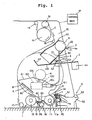
- a loom has a built-in device for automatically exchanging a full cloth beam for empty one according to an embodiment of the present invention.
- the automatic cloth beam exchanging device consists of a cloth beam driving mechanism 1, an empty cloth beam holder 2 having a releasing mechanism 3, a damper mechanism 4, a full cloth beam support stand 5, a full cloth beam ejecting mechanism 6, a cutter mechanism and a winding mechanism 8.
- the cloth beam driving mechanism 1 is of the so-called surface drive type and includes a pair of parallel front and rear rollers 11 and 12 extending transversely of the loom, i.e., extending between opposite side frames 10 and 10 of the loom and rotatably installed on the front lower end portions thereof.
- the terms "front” and “rear”, “forwardly” and “rearwardly”, etc. are herein used to indicate the positions and directions in the loom on the basis of the understanding that a warp beam is disposed at the "rear” of the loom and warp threads are supplied “forwardly” therefrom.
- the cylindrical outer peripheral portions of the rollers 11 and 12 are made of synthetic rubber or the like material so as to have a sufficient durability and frictional resistance to movement of a woven fabric relative thereto.
- One of the rollers 11 and 12, i.e., in this embodiment the rear roller 12 is drivingly connected to a surface roller 14 by way of a power transmitting mechanism including a chain, timing belt or the like.
- the surface roller 14 is installed on the side frames 10 and 10 at the front upper end portions thereof.
- a woven fabric "C” coming out of a reed (not shown) of the loom is wound on the cloth beam "A” after passing sequentially through a guide bar 13, surface roller 14, press roller 15, upper guide bar 16 adjacent the surface roller 14, lower guide bar 17 adjacently rearward of the rear roller 12, bent bar 18 between the front and rear rollers 11 and 12 and the space between the cloth beam "A” and the front roller 11.
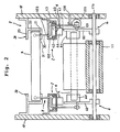
- the empty cloth beam holder 2 includes a pair of holder members 2a and 2a located above the front and rear rollers 11 and 12 and secured to the respective side frames 10 and 10.
- Each holder member 2a has a channel-shaped support portion consisting of an upper wall 20, a lower wall 21 and a vertical wall between the outer ends of the upper and lower walls 20 and 21.
- the holder members 2a and 2a are constructed and arranged so that an empty cloth beam "B" is movably received at the opposite axial end portions thereof in the channel-shaped support portions. Further, the holder members 2a and 2a are arranged so that the lower walls 21 descend toward the front and rear rollers 11 and 12.
- the empty cloth beam "B" is of the same structure as the cloth beam "A".
- the empty cloth beam holder 2 has a releasing mechanism 3 which is movable between a position where it allows the empty cloth beam "B" to be held within the holder members 2a and 2a and a position where it allows the empty cloth beam “B” to be release from the holder members 2a and 2a.
- the releasing mechanism 3 includes upstanding stopper bars 30 and 30 capable of protruding at the upper end portions thereof into the respective holder members 2a and 2a through elongated openings 31 formed in the lower walls 21 of each holder members 2a and 2a to abut upon the opposite axial end portions of the empty cloth beam "B" and thereby hold the same in the holder members 2a and 2a.
- the damper mechanism 4 includes a pair of damper arms 40 and 40 disposed between the respective empty cloth beam holders 2 and the cloth beam driving mechanism 1 for catching the empty cloth beam "B" released from the empty cloth beam holder 2 and on the way to the front and rear rollers 11 and 12.
- the damper mechanism 4 further includes cams 41 and 41 for contact with the damper arms 40 and 40 for controlling operation thereof.
- the damper arms 40 and 40 are elongated in the front-to-rear direction of the loom.
- the intermediate portion of each damper arm 40 i.e., the portion intermediate between the opposite longitudinal ends thereof is swingably installed by a pin 42 on a guide bracket 102 which is in turn installed on the corresponding side frame 10.
- Each damper arm 40 has an obtusely angled rear end portion 43 and is provided with a weight 44 at a front end thereof.
- the weight 44 is designed so as to make the angled rear end portion 43, when not supporting the empty cloth beam "B", turn upwards about the pin 42 and therefore the damper arm 40 abut upon the lower wall 21 of the corresponding holder member 2a and, when supporting the empty cloth beam "B", turn downwards about the pin 42 due to the weight of the empty cloth beam "B”.
- the damper arms 40 and 40 are adapted, during the downward movement of the angled rear end portions 43, not to interfere with the releasing mechanism 3 of the empty cloth beam holder 2, the full cloth beam ejecting mechanim 6, etc.
- the full cloth beam support stand 5 is used for supporting the full cloth beam "A” on which a predetermined length of woven fabric "C" is wound.
- the support stand 5 is arranged in the place forward of the front roller 11 and installed on the side frames 10 and 10.
- the full cloth beam support stand 5 includes an elongated base block 50 disposed between the side frames 10 and 10 and having at a rear upper end portion thereof an inclined support plate 51 descending forwardly and at a front upper end portion thereof a support bar 52.
- the support plate 51 and support bar 52 are spaced apart a predetermined distance in the front-to-rear direction of the loom and adapted to support thereon the full cloth beam "A", i.e., adapted to support the outer periphery of the rolled woven fabric of the cloth beam "A".
- the full cloth beam ejecting mechanism 6 is installed on the side frames 10 at the front lower end portions thereof for driving the full cloth beam "A" out of the place on the front and rear rollers 11 and 12 and placing the same on the full cloth beam support stand 5.
- the ejecting mechanism 6 includes a pair of vertical base plates 60 rotatably installed at one end portions thereof on a support shaft 11a of the front roller 11.
- Each base plate 60 has at the other end portion thereof an ejecting arm 61 in the form of an elongated plate and projecting inwardly of the loom.
- the ejecting arms 61 and 61 are arranged so as to descend forwardly when brought into contact with the cloth beam "A" on the front and rear rollers 11 and 12 and assume nearly vertical positions when the cloth beam "A" is about to go over the front roller 11 being driven by the ejecting arms 61 and 61.
- the ejecting arms 61 and 61 when they are in their rest positions or rearmost positions, they are positioned so as to decend forwardly, i.e., they are inclined toward the front and rear rollers 11 and 12 so as to be capable of introducing the empty cloth beam "B" into the space between front and rear rollers 11 and 12.
- cams 41 and 41 of the damper mechanism 4 are formed integrally with the pivotal base plates 60 of the full cloth beam ejecting mechanism 6. That is, the cams 41 and 41 are formed in the other end portions of the respective pivotal base plates 60 for controlling the operation of the damper arms 40 and 40 in such a manner that, when the base plates 60 and 60 of the ejecting mechanism 6 are in their rearmost positions or rest positions, the angled rear end portions 43 and 43 of the damper arms 40 and 40 turn downwardly about the pins 42 and 42 and into the positions where they release the empty cloth beam "B".
- the cams 41 and 41 are moved into the positions where they are capable of supporting the damper arms 40 and 40 nearly horizontally prior to releasing of the empty cloth beam "B" from the empty cloth beam holder 2 and operative to allow the damper arms 40 and 40 to turn downwardly about the pins 42 and 42 and into the positions where the angled rear end portions 43 and 43 release the empty cloth beam "B” after the upper ends of ejecting arms 61 and 61 of the ejecting mechanism 6 are positioned at least rearward of the empty cloth beam "B".
- the base plates 60 and 60 of the full cloth beam ejecting mechanism 6 are adapted to return to the rearmost or rest positions before the empty cloth beam "B" is released from the angled rear end portions 43 and 43 of the damper arms 40 and 40.
- the cutter mechanism 7 is disposed between the front roller 11 and the full cloth beam support stand 5 and has a cutter carrier 7a (refer to Fig. 7) adapted to move from one of the side frames 10 and 10 to the other (i.e., in the direction normal to the surface of the drawing of Fig. 1) being guided by a cutter guide 70 to cut the woven fabric "C" in the place between the full cloth beam "A” on the full cloth beam support stand 5 and the empty cloth beam “B" on the front and rear rollers 11 and 12.
- a cutter carrier 7a (refer to Fig. 7) adapted to move from one of the side frames 10 and 10 to the other (i.e., in the direction normal to the surface of the drawing of Fig. 1) being guided by a cutter guide 70 to cut the woven fabric "C" in the place between the full cloth beam "A” on the full cloth beam support stand 5 and the empty cloth beam “B” on the front and rear rollers 11 and 12.
- the cutter mechanism 7 is described more in detail with reference to Figs. 7 to 10.
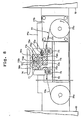
- the cutter mechanism 7 mainly consists of the cutter carrier 7a having a carrier body 71, a rotary cutter blade 72 rotatably installed on the carrier body 71, a turbine 73 serving as a fluid-drive motor for driving the rotary cutter blade 72 and a carrier drive unit 77.
- the turbine 73 includes a turbine rotor 73a consisting of a cylindrical rotor body 73b, a plurality of vanes 73c on the peripheray of the rotor body 73b and integral with same and a concentric rotor shaft 73d.
- the rotor shaft 73d projects forwardly from the rotor body 73b to have a front side portion on which an inner spacer 73f and a bearing 73e are installed and secured thereto with a nut 73g.
- the rotor shaft 73d also projects rearwardly from the rotor body 73b to have a rear side portion on which a bearing 73h, an inner spacer 73i and an outer spacer 73j are installed and secured thereto with a nut 73k.
- the turbine rotor 73a is rotatably installed in the carrier body 71 by disposing the rotor body 73b and vanes 73c in a turbine chamber 73l formed in the carrier body 71 and supporting the rotor shaft 73d upon the carrier body 71 by way of the bearings 73e and 73h.
- An inlet 73m and outlet 73n in communication with the turbine chamber 73l are formed in the carrier body 71.
- the inlet 73m is connected with a hose plug 73o which is in turn connected with a piping member 73p as a flexible vinyl tube.
- the other end of the piping member 73p is connected with an unshown pressurized fluid source as an air pump, air tank, etc. by way of an electromagnetic directional control valve (not shown).
- the rotary cutter blade 72 is installed on the rear side portion of the rotor shaft 73d and secured thereto together with the bearing 73h and the spacers 73i and 73j with the nut 73k to rotate together therewith.
- the rotary cutter blade 72 is arranged so as to be spaced rearwardly from the carrier body 71.
- a cover 74 is installed on the carrier body 71 for covering the rotary cutter blade 72.
- the cover 74 has a dual-walled portion for covering an upper peripheral portion of the rotary cutter blade 72.
- the dual-walled portion of the cover 74 is formed with a pair of horizontal slits 74a and 74b opposed in the lateral direction of the loom for exposing horizontally opposed, upper peripheral portions of the rotary cutter blade 72.
- the left and right carrier rollers 75 and 76 are installed on the cutter guide 70 so that the cutter carrier 7a is movable laterally of the loom, i.e., in the left-hand and right-hand directions in Fig. 8 being guided by the cutter guide 70.
- the carrier drive unit 77 includes a base plate 77a disposed between the side frames 10 and 10.
- a drive motor 77b is installed on one lateral end portion of the base plate 77a and located laterally outward of one longitudinal end of the cutter guide 70.
- a driven pulley 77d is installed on the other end portion of the base plate 77a and located laterally outward of the other longitudinal end of the cutter guide 70.
- the motor 77b is connected with a driving pulley 77c.
- a wire 77e is placed around the driving and driven pulleys 77c and 77d and connected at one end to one lateral end of the carrier body 71 by way of a spring 77f and at the other end to the other lateral end of the carrier body 71.
- the winding mechanism 8 is provided for winding the loom side cut end portion "Ca" of the woven fabric "C” on the empty cloth beam "B” having supplied from the empty cloth beam holder 2 to the front and rear rollers 11 and 12.
- the winding mechanism 8 includes a blow-up nozzle 80, separator nozzle 81, blow-in nozzle 82 and a guide plate 73.
- the blow-up nozzle 80 is disposed between the front roller 11 and the full cloth beam support stand 5 and adapted to blow air up to the peripheral surface of the empty cloth beam "B" just after the cutting of the woven fabric "C” so that the loom side cut end portion "Ca” of the woven fabric “C” is blown up to lie on the empty cloth beam "B".
- the blow-up nozzle 80 consists of a pipe 80a extending substantially straightly in the width direction of the woven fabric "C" and installed on a rear wall of the cutter guide 70 and a plurality of injection ports 80b formed in the rear upper peripheral portion of the pipe 80a in such a way as to be spaced from each other in the lateral direction of the loom, i.e., in the width direction of the woven fabric "C".
- the pipe 80a has an end connected through an electromagnetic directional control valve (not shown) to a pressurized air source as an air pump or an air tank and the other end sealingly closed.
- the injection ports 80b as shown in Fig. 11, are concentrically formed in respective plugs 80c which are in turn screwed into the peripheral wall of the pipe 80a.
- the separator nozzle 81 is disposed between the front and rear rollers 11 and 12 for separating the cut end portion "Ca" of the woven fabric "C” from the rear roller 12 when it comes downwardly from the space between the empty cloth beam “C” and the rear roller 12 while lying on the rear roller 12.
- the separator nozzle 81 consists of a square pipe 81a secured to the bent bar 18 by means of a bracket 84 and a plurality of injection ports formed in the upper wall of the square pipe 81a in such a way as to be spaced from each other in the width direction of the woven fabric "C".
- the square pipe 81a is elongated substantially straightly in the width direction of the woven fabric "C" and communicated at one end with the above described pressurized air source through an electromagnetic directional control valve (not shown) independent from the above described directional control valve and sealingly closed at the other end so as to define a fluid passage 91 within the square pipe 81a.
- the injection ports 81b are, similarly to the above described injection ports 80b, concentrically formed in respective plugs 81c which are in turn screwed into the upper wall of the square pipe 81a.
- the blow-in nozzle 82 is disposed between the front and rear rollers 11 and 12 for blowing the cut end portion "Ca" of the woven fabric "C" into the space between the empty cloth beam "B" and the front roller 11.
- the blow-in nozzle 82 is constituted by the above described square pipe 85 and a plurality of injection ports 82b formed in the front wall thereof in such a manner as to be spaced in the width direction of the woven fabric "C".
- the injection ports 82b are, similarly to the injection ports 81b, concentrically formed in plugs 82c which are in turn screwed into the front front wall of the square pipe 81a.
- the guide plate 83 is installed on the bracket 84 so as to guide the loom side cut end portion "Ca" of the woven fabric "C” which is blown by the air from the blow-in nozzle 82 into the space between the front roller 11 and the cloth beam B on the front and rear rollers 11 and 12.
- the full cloth beam ejecting mechanism 6 and the releasing mechanism 3 of the empty cloth beam holder 2 are operative in timed relation to each other and adapted to be driven by the same air cylinders 100 and 100 installed on the respective side frames 10 and 10. More specifically, the stopper bars 30 and 30 of the releasing mechanism 3 extend downwardly to have the other end portions which are connected by means of pins 101 and 101 to the respective base plates 60 and 60 of the ejecting mechanism 6. The intermediate portions of the stopper bars 30 and 30 are movably received in guide holes 103 and 103 formed in the guide brackets 102 and 102 which are in turn installed on the side frames 10 and 10. The pins 101 and 101 are connected with piston rods 104 and 104 of the air cylinders 100 and 100. Cylinder tubes 105 and 105 of the air cylinders 100 and 100 are installed on the respective side frames 10 and 10 by means of pins 106.
- the automatic cloth beam exchanging device built in the loom operates as follows.
- the air cylinders 100 and 100 are actuated so as to project the piston rods 104 and 104 outwards therefrom while continuing the weaving operation of the loom.
- the ejecting arms 61 and 61 of the ejecting mechanism 6 turn forwardly about the supporting shaft 11a while driving the cloth beam "A” out of the place on the front and rear rollers 11 and 12 and beyond the uppermost portion of the front roller 11 so that the cloth beam "A” goes over the front roller 11 and moves forwardly by the effect of the weight of itself onto the full cloth beam support stand 5.
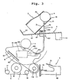
- the woven fabric "C” extends continuously from the bent bar 18 through the front roller 11 and support plate 51 to the cloth beam "A” on the full cloth beam support stand 5. Further, by the forward movement of the ejecting arms 61 and 61 of the ejecting mechanism 6, the cams 41 and 41 are moved into the positions under the angled rear end portions 43 and 43 of the damper arms 40 and 40 and at the same time the stopper bars 30 and 30 of the releasing mechanism 3 withdraw from the inside of the holder members 2a and 2a, following the path indicated by the one-dot chain line in Fig. 4 and being guided by the guide holes 103 and 103.
- the empty cloth beam “B” thus moves down on the lower walls 21 and 21 of the holder members 2a and 2a due to the weight of itself to be caught by the angled rear end portions 43 and 43 of the damper arms 40 and 40.
- the angled rear end portions 43 and 43 having caught the cloth beam “B” turn downwards a little about the pins 42 and 42 due to the weight of the empty cloth beam “B” and come to contact the cams 41 and 41 to be supported thereon as shown in Fig. 4.
- the air cylinders 100 and 100 are actuated so as to retract the piston rods 104 and 104 thereinto.
- the ejecting arms 61 and 61 of the ejecting mechanism 6 are turned rearwards about the support shaft 11a.
- the cams 41 and 41 are moved out of the positions under the angled rear end portions 43 and 43, thus allowing the angled rear end portons 43 and 43 of the damper arms 40 and 40 to turn donwnwards about the pins 42 and 42 under the control of the cams 42 and 42 and due to the weight of the empty cloth beam "B".
- the empty cloth beam "B” is thus released from the angled rear end portions 43 and 43 of the damper arms 40 and 40 and supplied onto the front and rear rollers 11 and 12 while being held parallel to the axes of the rollers 11 and 12 so as to be assuredly placed thereon.
- the motor 77b is actuated so as to rotate in a predetermined direction, i.e., in the anticlockwise direction in Fig. 8 before the cloth beam "A" is ejected from the front and rear rollers 11 and 12 and goes beyond the front roller 11.
- the carrier drive unit 77 causes the cutter carrier 7a to move from the position laterally outward of one side of the woven fabric "C” as shown by the solid line in Fig. 9 to the position laterally outward of the other side of the woven fabric "C” as shown by the two-dot chain line in Fig. 9. That is, the cutter carrier 7a is first moved from one side of the woven fabic "C" to the other for thereby making ready for the cutting operation.
- pressurized fluid from the pressurized fluid source is supplied to the inlet 73m of the turbine 73, thus causing the turbine rotor 73a to rotate at high speed together with the rotary cutter blade 72.
- the motor 77b is actuated so as to rotate reversely.
- the cutter carrier 7a is driven to move in the opposite direction while introducing the woven fabric "C" into the slit 74b, i.e., the right-hand slit 74b in Fig. 8, and to the rotary cutter blade 72 and allowing the same to be cut thereby.
- the motor 77b is stopped for thereby stopping movement of the cutter carrier 7a and at the same time the supply of pressurized air to the turbine 73 is stopped.
- the loom side cut end portion "Ca” of the woven fabric “C” is wound on the empty cloth beam "B" installed on the front and rear rollers 11 and 12 as shown in Fig. 6. That is, the nozzles 80 first blow air in the direction of the arrow X1 so that the front roller side cut end portion "Ca” is laid on the empty cloth beam "B” and then stop blowing air after lapse of a predetermined time. By this, the loom side cut end portion "Ca” of the woven fabric “C” is laid on the outer periphery of the empty cloth beam "B” and moves together with the empty cloth beam "B".
- the cut end portion "Ca” then passes through the space between the rear roller 12 and the empty cloth beam “B” to project downwardly therefrom.
- the separator nozzles 81 and blow-in nozzles 82 blow air in the respective directions X2 and X3.
- the loom side cut end portion "Ca” projecting from the rear roller 12 and the empty cloth beam “B” is separated from the rear roller 12 by the effect of the air from the separator nozzles 81 and thus passes through the space between the square pipe 81a and the empty cloth beam "B” to be blown toward the guide plate 83.
- the blow-in nozzle 82 injects air in the direction X3 which crosses the front-to-rear direction of extension of the guide plate 83 and cooperates with the guide plate 83 to guide the air injected from the blow-in nozzle 82 in the direction X4 to the space between the cloth beam "B" and the front roller 11.
- the guide plate 83 is adjustable in inclination, i.e., movable forwardly and rearwardly as indicated by the arrows in Fig. 11, the blowing direction X4 can be adjusted suitably.
- the separating nozzles 81 and blow-in nozzles 82 stop blowing air. By this, one cloth beam exchanging cycle is completed.
- a cloth beam carrier is called to convey the full cloth beam "B" to a predetermined storing place as a cloth beam carrier store.
- a new cloth beam is supplied to the empty cloth beam holder 2 to ready for the next cloth beam exchange.
- the empty cloth beam "B” is supplied to the empty cloth beam holder 2, it is held thereat since the the stopper bars 30 and 30 of the releasing mechanism 3 are now positioned so as to intrude into the respective holder members 2a and 2a in response to returning of the full cloth beam ejecting mechanism 6 to its rest position.
- the control unit 10 is adapted to count the number of picks to know the length of woven fabric based on the number of picks and the number of weft threads per unit length. Further, the control unit 10 can know the weaving operation time necessary for the cloth beam to wind thereon a predetermined length of woven fabric, on the basis of the above informations and the speed of operation of the loom.
- a signal is produced at step "S1" and a predetermined time (e.g., 15 to 30 minutes) before a predetermined length (e.g., 150 m) of woven fabric is wound on the cloth beam "A” for notifying the necessity of a cloth beam unloading operation.
- a predetermined time e.g. 15 to 30 minutes
- a predetermined length e.g. 150 m
- a warning lamp is turned on to call for an empty cloth beam "B", i.e., to notify the worker of the fact so that he can supply an empty cloth beam "B” to the empty cloth beam holder 2 at step "S4".
- step "S5" a cut mark signal is produced when it is detected that a predtermined length of woven fabric "C” is produced by the loom.
- step “S6" when it is detected on the basis of the cut mark signal that a predtermined length of woven fabric "C” is wound on the cloth beam "A”, the front roller 11 of the driving mechanism 1 is stopped but the surface roller 14, etc. are kept rotating to continue a weaving operation of the loom.
- step “S7” it is judged once again whether an empty cloth "B” is installed on the empty cloth beam holder "2".
- the loom is stopped at step “S8", and a warning signal is produced at step "S9".
- the loom is started again at step "S11".
- step “S12” the ejecting arms 61 and 61 are actuated to eject the full cloth beam “A” out of the place on the front and rear rollers 11 and 12. By this, the full cloth beam “A” is supported on the full cloth beam support stand 5.
- step “S12” before the full cloth beam “B” ejected from the front and rear rollers 11 and 12 goes beyond the front roller 11, the rotary cutter blade 72 is started to rotate and at the same time the motor 77b is actuated to rotate in a predetermined direction for thereby moving the cutter carrier 7a from one side of the woven fabric "C" to the other to make ready for a cutting operation as having been described above.
- step “S13" it is judged, by using a limit switch or the like installed on the full cloth beam support stand 5, whether the full cloth beam "A” is removed from the front and rear rollers 11 and 12 and supported on the full cloth beam support stand 5.
- the control is returned back to step “S12” through the step “S14” to perform the above judgement again.
- the loom is stopped at step “S15” to produce a warning signal at step "S16".
- step “S19” it is judged whether the empty cloth beam "B” is released from the empty cloth beam holder 3 and installed on the front and rear rollers 11 and 12 by using a photoelectric sensor or the like disposed in the cloth beam driving mechanism 1.
- the loom is stopped at step "S20", and an alarm signal is produced at step "21".
- step “S22” the motor 77b is actuated to rotate reversely to the above described predetermined direction for thereby moving the cutter carrier 7a in the corresponding direction and cutting the woven fabric "C".
- step “S23” it is judged whether the woven fabric "C” is cut when the cutter carrier 7a is moved into a predetermined position laterally outward of the corresponding side of the woven fabric "C” and finishes a cutting operation.
- the control is returned through step “S24” to the step “S22” to perform a cutting operation again.
- the loom is stopped at step “S25” and an alarm signal is produced at step "S26".
- the blow-up nozzle 80 is started to blow air for placing the loom side cut end portion "Ca” of the woven fabric "C” on the empty cloth beam "B".
- the rear roller 12 is started to rotate.
- the separator nozzle 81 and blow-in nozzle 82 are started to blow air.
- step “S30” it is judged whether the loom side cut end portion "Ca” of the woven fabric "C” is wound on the empty cloth beam "B".
- the loom is stopped at step “S31”, and an alarm signal is produced at step "S32".
- a colth beam carrier is called for to unload the full cloth beam "A” from the loom and convey it to a predetermined place as a cloth beam carrier store.
- Fig. 15 shows a variant of the full cloth beam support 5 in which a pair of secondary supports 53 in the form of vertical plates are installed on the base block 50 so as to support thereon the opposite end portions of the full cloth beam “A” projecting outwardly from the rolled woven fabric "C" when the outer diameter of the full cloth beam "A” is smaller than a predetermined value, i.e., the length of woven fabric "C” wound on the cloth beam “A” is smaller than a predtermined value.
- a predetermined value i.e., the length of woven fabric "C” wound on the cloth beam “A” is smaller than a predtermined value.
- the full cloth beam “A” When the outer diameter of the full cloth beam “A” is larger than a predetermined value, i.e., the length of woven fabric “C” wound on the cloth beam “A” is larger than a predetermined value, the full cloth beam “A” is not supported at the opposite end portions on the secondary supports 53 but is supported at the outer peripherty of the rolled cloth beam “C” on the empty cloth beam stand 5, thus providing a sufficient space between the opposite end portions of the cloth beam “A” and the support stand 5.
- a cloth beam “A” of a small outer diameter can be unloaded from the loom with ease by using a cloth beam carrier.
- the empty cloth beam "B” stored in the empty cloth beam holder 2 is adapted to fall on the cloth beam driving mechanism 1 stepwisely by means of the damper mechanism 4, it becomes possible to assuredly hold the empty cloth beam “B” in parallel to the front and rear rollers 11 and 12 while at the same time to reduce the striking force or impact against the cloth beam driving mechanism 1.
- the releasing mechanism 3 of the empty cloth beam holder 2 and the ejecting mechanism 6 are mechanically connected so as to operate in timed relation to each other, thus making it possible to control the timing at which the empty cloth beam "B" is released from the empty cloth beam holder 2 can be controlled accurately and assuredly.
- cams 41 and 41 of the damper mechanism 4 are formed integral with the base plates 60 and 60 of the ejecting mechanism 6, thus making it possible to control the timing at which the empty cloth beam holder "B" is released from the damper arms 40 and 40 accurately and assuredly.
- the cutter mechanism 7 does not require the woven fabric "C” to be tense or stretched when the woven fabric "C” is to be cut thereby.
- the cutting mechanism 7 can attain a beautifully or clearly cut end when the woven fabric "C” is cut in a loose state, i.e., can cut the woven fabric "C” in a loose state without causing any deffect, i.e., without substantially causing any unwoven or separated threads at the cut end portion "Ca”.
- the rotary turbine blade 72 is driven by the fluid-drive motor, i.e., by the turbine 73 to rotate at high speed, e.g., at the speed ranging from about 30,000 to 60,000 rpm.
- the rotary cutter blade 72 can be rotated at such high speed by the combination of the rotary cutter blade 72 and the turbine 72 serving as a fluid-drive motor according to this invention.
- the winding mechanism 8 consists of three kinds of air nozzles and can assuredly wind the loom side cut end portion "Ca" of the woven fabric "C” on a new cloth beam "B".
- the winding mechanism 8 is simple and compact in structure but reliable in operation.
- the driving mechanism 1, the cutter mechanism 7 and the winding mechanism 8 are adapted to be actuated by pressurized fluid as pressurized air or pressurized water.
- pressurized air or water is available with ease, particularly in case of an air jet loom or water jet loom and therefore this makes it possible for making the cloth beam exchanging device further compact in size, simple in structure and reliable in operation.
- the empty cloth beam stocker 2 and the ejecting mechanism 6 are constructed and arranged so as to be simple and compact in structure, i.e., so as not to increase particularly the front-to-rear length of the loom. This is therefore effective for retaining a space for movement of a cloth beam carrier between the looms.
- the releasing mechanism 3 may be constituted, as shown in Fig. 16 by a pair of angled levers 302 and 302 swingablly installed at intermediate potions thereof on stationary pins 300 and 300 and having one ends formed with abutment fingers 301 and 301 for abutment with the empty cloth beam "B" and the other ends abuttingly engageable with stopper pins 600 and 600 installed on the respective base plates 60 and 60.
- the levers 302 and 302 are urged by springs 303 and 303 into the positions where the abutment fingers 301 and 301 are abuttingly engageable with the cloth beam "B" for holding the same in the holder members 2a and 2a.
- the levers 302 and 302 are movable into the positions where the abutment fingers 301 and 301 are moved out of the positions for abutment with the cloth beam "B" in the holder members 2a and 2a being driven by the stopper pins 600 and 600 when the base plates 60 and 60 of the ejecting mechanism 6 are driven into predetermined forward positions.
- the releasing mechanism 3 of the empty cloth beam holder 2 has been described shown as above, it is not limitative but may be considered, in a broader sense, as a supplying mechanism for supplying the cloth beam "B" from the cloth beam holder 2 to the driving mechanism 1.
Landscapes
- Engineering & Computer Science (AREA)
- Textile Engineering (AREA)
- Looms (AREA)
Applications Claiming Priority (4)
| Application Number | Priority Date | Filing Date | Title |
|---|---|---|---|
| JP144121/89 | 1989-06-08 | ||
| JP1144121A JPH0314656A (ja) | 1989-06-08 | 1989-06-08 | 織機における布巻ロール交換装置 |
| JP1207504A JP2958397B2 (ja) | 1989-08-10 | 1989-08-10 | 織機の布巻きロール交換装置 |
| JP207504/89 | 1989-08-10 |
Publications (1)
| Publication Number | Publication Date |
|---|---|
| EP0401824A1 true EP0401824A1 (de) | 1990-12-12 |
Family
ID=26475644
Family Applications (1)
| Application Number | Title | Priority Date | Filing Date |
|---|---|---|---|
| EP19900110811 Withdrawn EP0401824A1 (de) | 1989-06-08 | 1990-06-07 | Webstuhl mit einer Vorrichtung zum automatischen Warenbaumwechseln |
Country Status (3)
| Country | Link |
|---|---|
| US (1) | US5063970A (de) |
| EP (1) | EP0401824A1 (de) |
| KR (1) | KR930000172B1 (de) |
Cited By (1)
| Publication number | Priority date | Publication date | Assignee | Title |
|---|---|---|---|---|
| WO2000007747A1 (de) * | 1998-08-04 | 2000-02-17 | Sms Schloemann-Siemag Aktiengesellschaft | Umlenkverfahren und umlenkeinrichtung für ein band, insbesondere ein metallband |
Families Citing this family (6)
| Publication number | Priority date | Publication date | Assignee | Title |
|---|---|---|---|---|
| US5257748A (en) * | 1989-09-27 | 1993-11-02 | Krantz America, Inc. | Sheet winding apparatus |
| US5265649A (en) * | 1991-07-10 | 1993-11-30 | Kabushiki Kaisha Toyoda Jidoshokki Seisakusho | Cloth roll exchange apparatus for a loom |
| JP3054266B2 (ja) * | 1992-04-27 | 2000-06-19 | 津田駒工業株式会社 | クロスロール交換装置 |
| CN103306025B (zh) * | 2013-05-23 | 2014-12-03 | 苏州市丹纺纺织研发有限公司 | 一种收卷轴落布升降结构 |
| IT201800009199A1 (it) * | 2018-10-05 | 2020-04-05 | Tecno Paper Srl | Ribobinatrice da cartiera con dispositivo di cambio bobina in continuo |
| CN113772467B (zh) * | 2021-08-25 | 2023-08-04 | 连云港鹰游新立成纺织科技有限公司 | 布料自动打卷包装装置 |
Citations (5)
| Publication number | Priority date | Publication date | Assignee | Title |
|---|---|---|---|---|
| US4196865A (en) * | 1978-10-19 | 1980-04-08 | Patriksson Stig S | Method for the transfer of a forwards-travelling material web from a first take-up roller to a second take-up roller and means for carrying out the method |
| GB2085413A (en) * | 1980-10-21 | 1982-04-28 | Waertsilae Oy Ab | Guiding leading web end onto roll core |
| EP0078493A1 (de) * | 1981-11-02 | 1983-05-11 | Schwab Maschinenbau GmbH & Co. | Vorrichtung zum Aufwickeln einer Warenbahn |
| WO1986001186A1 (fr) * | 1984-08-10 | 1986-02-27 | Heinrich Schnell | Dispositif d'enroulement d'articles en bandes |
| US4606381A (en) * | 1984-02-16 | 1986-08-19 | Tsudakoma Kogyo Kabushiki Kaisha | Method and apparatus for automatically exchanging cloth rollers in a loom |
Family Cites Families (3)
| Publication number | Priority date | Publication date | Assignee | Title |
|---|---|---|---|---|
| CH503819A (de) * | 1970-04-09 | 1971-02-28 | Sulzer Ag | Webmaschine |
| DE3870044D1 (de) * | 1987-06-16 | 1992-05-21 | Sulzer Ag | Transportgeraet fuer weberei. |
| JPH0197241A (ja) * | 1987-10-06 | 1989-04-14 | San M Shokai:Kk | 織機のクロスローラ交換装置 |
-
1990
- 1990-06-07 EP EP19900110811 patent/EP0401824A1/de not_active Withdrawn
- 1990-06-07 US US07/534,638 patent/US5063970A/en not_active Expired - Fee Related
- 1990-06-08 KR KR1019900008386A patent/KR930000172B1/ko not_active Expired - Fee Related
Patent Citations (5)
| Publication number | Priority date | Publication date | Assignee | Title |
|---|---|---|---|---|
| US4196865A (en) * | 1978-10-19 | 1980-04-08 | Patriksson Stig S | Method for the transfer of a forwards-travelling material web from a first take-up roller to a second take-up roller and means for carrying out the method |
| GB2085413A (en) * | 1980-10-21 | 1982-04-28 | Waertsilae Oy Ab | Guiding leading web end onto roll core |
| EP0078493A1 (de) * | 1981-11-02 | 1983-05-11 | Schwab Maschinenbau GmbH & Co. | Vorrichtung zum Aufwickeln einer Warenbahn |
| US4606381A (en) * | 1984-02-16 | 1986-08-19 | Tsudakoma Kogyo Kabushiki Kaisha | Method and apparatus for automatically exchanging cloth rollers in a loom |
| WO1986001186A1 (fr) * | 1984-08-10 | 1986-02-27 | Heinrich Schnell | Dispositif d'enroulement d'articles en bandes |
Cited By (3)
| Publication number | Priority date | Publication date | Assignee | Title |
|---|---|---|---|---|
| WO2000007747A1 (de) * | 1998-08-04 | 2000-02-17 | Sms Schloemann-Siemag Aktiengesellschaft | Umlenkverfahren und umlenkeinrichtung für ein band, insbesondere ein metallband |
| US6578789B1 (en) | 1998-08-04 | 2003-06-17 | Sms Schloemann-Siemag Aktiengesellschaft | Deflection method and deflection device for a strip, especially a metal strip |
| RU2221661C2 (ru) * | 1998-08-04 | 2004-01-20 | Смс Шлеманн-Зимаг Акциенгезелльшафт | Отклоняющее устройство для отклонения ленты, в частности, металлической ленты |
Also Published As
| Publication number | Publication date |
|---|---|
| US5063970A (en) | 1991-11-12 |
| KR930000172B1 (ko) | 1993-01-11 |
| KR910001123A (ko) | 1991-01-30 |
Similar Documents
| Publication | Publication Date | Title |
|---|---|---|
| US5063970A (en) | Loom with device for automatically exchanging cloth beams | |
| FR2523101A1 (fr) | Dispositif de transport de fuseaux pour bobinoir automatique | |
| US4322943A (en) | Device for joining an upper thread to a lower thread | |
| US3544018A (en) | Bobbin handling | |
| FI89384C (fi) | Automatisk vaexelanordning foer en vaeftspole | |
| US3920193A (en) | Winding apparatus with automatic changing of tubes or the like | |
| US5016680A (en) | Weft processing and releasing apparatus in a jet loom | |
| US5431353A (en) | Bobbin winding machine | |
| JP2578505Y2 (ja) | 織機の布巻きロール交換装置 | |
| JP3220878B2 (ja) | 織機の布巻きロール交換装置 | |
| JPH0369640A (ja) | 織機の布巻き付け装置 | |
| JP2958397B2 (ja) | 織機の布巻きロール交換装置 | |
| JPH06305615A (ja) | 織機の布巻ロール交換装置 | |
| EP0401827A1 (de) | Vorrichtung zum Absaugen von auf Vorgarnspulen verbliebenen Luntenresten | |
| JPH06115777A (ja) | 織機の布巻きロール交換装置 | |
| FI89813B (fi) | Automatisk utbytesanordning foer en vaeftspole vid vaevstol av skytteltyp | |
| EP1721034B1 (de) | Vorrichtung zur webrandbildung, webmaschine mit webrandbildungsvorrichtung und verfahren zur bildung eines webrands | |
| US4693430A (en) | Winding station of an automatic winding machine | |
| US5107905A (en) | Pneumatic device for conveyance of weft thread to a prewinder | |
| EP0488954B1 (de) | Vorrichtung zum Handhaben von Schussfäden in einer Düsenwebmaschine | |
| JPH0637243U (ja) | 織機の布巻きロール交換装置 | |
| JP3324226B2 (ja) | 粗糸替機の粗糸たるみ吸収装置及び粗糸たるみ吸収方法 | |
| US3897911A (en) | Creel for automatic winding machine | |
| JPH06135605A (ja) | 織機の布巻きロール交換装置 | |
| US2729398A (en) | Yarn tail disposal device for automatic bobbin winding machines |
Legal Events
| Date | Code | Title | Description |
|---|---|---|---|
| PUAI | Public reference made under article 153(3) epc to a published international application that has entered the european phase |
Free format text: ORIGINAL CODE: 0009012 |
|
| 17P | Request for examination filed |
Effective date: 19900607 |
|
| AK | Designated contracting states |
Kind code of ref document: A1 Designated state(s): FR IT |
|
| RIN1 | Information on inventor provided before grant (corrected) |
Inventor name: CHIKUMA, TAKAYUKI Inventor name: KANEKO, SUSUMU Inventor name: TANAKA, KAZUHIRO Inventor name: KOJIMA, SHUICHI |
|
| 17Q | First examination report despatched |
Effective date: 19930720 |
|
| RAP1 | Party data changed (applicant data changed or rights of an application transferred) |
Owner name: NISSAN TEXSYS CO., LTD. |
|
| GRAH | Despatch of communication of intention to grant a patent |
Free format text: ORIGINAL CODE: EPIDOS IGRA |
|
| GRAH | Despatch of communication of intention to grant a patent |
Free format text: ORIGINAL CODE: EPIDOS IGRA |
|
| STAA | Information on the status of an ep patent application or granted ep patent |
Free format text: STATUS: THE APPLICATION HAS BEEN WITHDRAWN |
|
| 18W | Application withdrawn |
Withdrawal date: 19961113 |