EP0402777A1 - Radaufhängung für ein lenkbares, angetriebenes Fahrzeugrad - Google Patents
Radaufhängung für ein lenkbares, angetriebenes Fahrzeugrad Download PDFInfo
- Publication number
- EP0402777A1 EP0402777A1 EP90110843A EP90110843A EP0402777A1 EP 0402777 A1 EP0402777 A1 EP 0402777A1 EP 90110843 A EP90110843 A EP 90110843A EP 90110843 A EP90110843 A EP 90110843A EP 0402777 A1 EP0402777 A1 EP 0402777A1
- Authority
- EP
- European Patent Office
- Prior art keywords
- hub
- suspension
- wheel carrier
- supported
- wheel
- Prior art date
- Legal status (The legal status is an assumption and is not a legal conclusion. Google has not performed a legal analysis and makes no representation as to the accuracy of the status listed.)
- Granted
Links
- 239000000725 suspension Substances 0.000 title claims abstract description 68
- 230000002093 peripheral effect Effects 0.000 claims description 6
- 210000002925 A-like Anatomy 0.000 description 2
- 238000006073 displacement reaction Methods 0.000 description 2
- 230000036316 preload Effects 0.000 description 2
- 239000006096 absorbing agent Substances 0.000 description 1
- 238000001816 cooling Methods 0.000 description 1
- 230000002452 interceptive effect Effects 0.000 description 1
- 230000002265 prevention Effects 0.000 description 1
- 230000008439 repair process Effects 0.000 description 1
- 230000035939 shock Effects 0.000 description 1
Images


Classifications
-
- B—PERFORMING OPERATIONS; TRANSPORTING
- B60—VEHICLES IN GENERAL
- B60G—VEHICLE SUSPENSION ARRANGEMENTS
- B60G3/00—Resilient suspensions for a single wheel
- B60G3/18—Resilient suspensions for a single wheel with two or more pivoted arms, e.g. parallelogram
- B60G3/20—Resilient suspensions for a single wheel with two or more pivoted arms, e.g. parallelogram all arms being rigid
- B60G3/26—Means for maintaining substantially-constant wheel camber during suspension movement ; Means for controlling the variation of the wheel position during suspension movement
- B60G3/265—Means for maintaining substantially-constant wheel camber during suspension movement ; Means for controlling the variation of the wheel position during suspension movement with a strut cylinder contributing to the suspension geometry by being linked to the wheel support via an articulation
-
- B—PERFORMING OPERATIONS; TRANSPORTING
- B60—VEHICLES IN GENERAL
- B60G—VEHICLE SUSPENSION ARRANGEMENTS
- B60G13/00—Resilient suspensions characterised by arrangement, location or type of vibration dampers
- B60G13/001—Arrangements for attachment of dampers
- B60G13/005—Arrangements for attachment of dampers characterised by the mounting on the axle or suspension arm of the damper unit
- B60G13/006—Arrangements for attachment of dampers characterised by the mounting on the axle or suspension arm of the damper unit on the stub axle
-
- B—PERFORMING OPERATIONS; TRANSPORTING
- B60—VEHICLES IN GENERAL
- B60G—VEHICLE SUSPENSION ARRANGEMENTS
- B60G15/00—Resilient suspensions characterised by arrangement, location or type of combined spring and vibration damper, e.g. telescopic type
- B60G15/02—Resilient suspensions characterised by arrangement, location or type of combined spring and vibration damper, e.g. telescopic type having mechanical spring
- B60G15/06—Resilient suspensions characterised by arrangement, location or type of combined spring and vibration damper, e.g. telescopic type having mechanical spring and fluid damper
- B60G15/07—Resilient suspensions characterised by arrangement, location or type of combined spring and vibration damper, e.g. telescopic type having mechanical spring and fluid damper the damper being connected to the stub axle and the spring being arranged around the damper
-
- B—PERFORMING OPERATIONS; TRANSPORTING
- B60—VEHICLES IN GENERAL
- B60G—VEHICLE SUSPENSION ARRANGEMENTS
- B60G3/00—Resilient suspensions for a single wheel
- B60G3/18—Resilient suspensions for a single wheel with two or more pivoted arms, e.g. parallelogram
- B60G3/20—Resilient suspensions for a single wheel with two or more pivoted arms, e.g. parallelogram all arms being rigid
-
- B—PERFORMING OPERATIONS; TRANSPORTING
- B60—VEHICLES IN GENERAL
- B60T—VEHICLE BRAKE CONTROL SYSTEMS OR PARTS THEREOF; BRAKE CONTROL SYSTEMS OR PARTS THEREOF, IN GENERAL; ARRANGEMENT OF BRAKING ELEMENTS ON VEHICLES IN GENERAL; PORTABLE DEVICES FOR PREVENTING UNWANTED MOVEMENT OF VEHICLES; VEHICLE MODIFICATIONS TO FACILITATE COOLING OF BRAKES
- B60T1/00—Arrangements of braking elements, i.e. of those parts where braking effect occurs specially for vehicles
- B60T1/02—Arrangements of braking elements, i.e. of those parts where braking effect occurs specially for vehicles acting by retarding wheels
- B60T1/06—Arrangements of braking elements, i.e. of those parts where braking effect occurs specially for vehicles acting by retarding wheels acting otherwise than on tread, e.g. employing rim, drum, disc, or transmission or on double wheels
- B60T1/065—Arrangements of braking elements, i.e. of those parts where braking effect occurs specially for vehicles acting by retarding wheels acting otherwise than on tread, e.g. employing rim, drum, disc, or transmission or on double wheels employing disc
-
- B—PERFORMING OPERATIONS; TRANSPORTING
- B60—VEHICLES IN GENERAL
- B60G—VEHICLE SUSPENSION ARRANGEMENTS
- B60G2200/00—Indexing codes relating to suspension types
- B60G2200/10—Independent suspensions
- B60G2200/17—Independent suspensions with a strut contributing to the suspension geometry by being articulated onto the wheel support
-
- B—PERFORMING OPERATIONS; TRANSPORTING
- B60—VEHICLES IN GENERAL
- B60G—VEHICLE SUSPENSION ARRANGEMENTS
- B60G2202/00—Indexing codes relating to the type of spring, damper or actuator
- B60G2202/30—Spring/Damper and/or actuator Units
- B60G2202/31—Spring/Damper and/or actuator Units with the spring arranged around the damper, e.g. MacPherson strut
- B60G2202/312—The spring being a wound spring
-
- B—PERFORMING OPERATIONS; TRANSPORTING
- B60—VEHICLES IN GENERAL
- B60G—VEHICLE SUSPENSION ARRANGEMENTS
- B60G2204/00—Indexing codes related to suspensions per se or to auxiliary parts
- B60G2204/10—Mounting of suspension elements
- B60G2204/12—Mounting of springs or dampers
- B60G2204/129—Damper mount on wheel suspension or knuckle
-
- B—PERFORMING OPERATIONS; TRANSPORTING
- B60—VEHICLES IN GENERAL
- B60G—VEHICLE SUSPENSION ARRANGEMENTS
- B60G2206/00—Indexing codes related to the manufacturing of suspensions: constructional features, the materials used, procedures or tools
- B60G2206/01—Constructional features of suspension elements, e.g. arms, dampers, springs
- B60G2206/50—Constructional features of wheel supports or knuckles, e.g. steering knuckles, spindle attachments
-
- F—MECHANICAL ENGINEERING; LIGHTING; HEATING; WEAPONS; BLASTING
- F16—ENGINEERING ELEMENTS AND UNITS; GENERAL MEASURES FOR PRODUCING AND MAINTAINING EFFECTIVE FUNCTIONING OF MACHINES OR INSTALLATIONS; THERMAL INSULATION IN GENERAL
- F16D—COUPLINGS FOR TRANSMITTING ROTATION; CLUTCHES; BRAKES
- F16D55/00—Brakes with substantially-radial braking surfaces pressed together in axial direction, e.g. disc brakes
- F16D2055/0004—Parts or details of disc brakes
- F16D2055/0008—Brake supports
Definitions
- This invention relates to a suspension for a steerable driving wheel in a vehicle and, more particularly, to a suspension in a vehicle provided with a wheel carrier rotatable around a steering axis, a hub for transmitting a driving force from a drive shaft to a wheel, and a brake disk for transmitting a brake force generated in cooperation with a brake caliper to the hub.
- a strut type suspension as shown in Fig. 9 (for instance, as described in "Repairs for Vista” issued March 24, 1982 by Toyota Jidosha Kabushiki Kaisha, on Page 3 - 33).
- a wheel carrier 10 In the suspension, a wheel carrier 10 has an upper portion firmly fixed to a strut 11, and the strut 11 is swingably supported to a vehicle body 13 through a support 12.
- the wheel carrier 10 has a lower portion swingably connected to a suspension arm 15 through a ball joint 14. Thereby, the wheel carrier 10 is permitted to rotate around a steering axis L (king pin axis) interconnecting the center O1 of the support 12 and the center O2 of the ball joint 14.
- a steering axis L king pin axis
- a drive shaft 16 is unrotatably connected to a hub 17 rotatably supported by the wheel carrier 10 through a bearing (not shown), and a disk wheel 18 of a wheel and a brake disk 19 are attached to the hub 17.
- the brake disk 19 generates a braking force in cooperation with a brake caliper (not shown).
- a point intersecting a rotary axis of a tire 20 and a vertical plane passing through the center of the grounding contact surface of the tire 20 each other is defined as I point
- a point intersecting the rotary axis of the tire 20 and the steering axis L each other in a condition to be projected on a surface parallel to the surface of Fig. 9 is defined as K point
- a driving force from the drive shaft 16 acts on the rotary axis of the tire at the time of driving of the vehicle, and a moment proportional to the I-K distance is generated by the driving force to make the tire tend to rotate around the steering axis L. Accordingly, since a steering wheel or handle is forced to be moved, a so-called steering effort is necessary to resist it.
- the I-K distance has to make small in order to lessen the steering effort.
- the center O1 of the support 12 or the center O2 of the ball joint 14 may be located laterally as outward as possible of the vehicle.
- the center O2 of the ball joint 14 is naturally limited in bringing its position outward in consideration that the brake disk 19 is located laterally outward of the ball joint 14 and the disk wheel 18 is incapable of varying its shape since the disk wheel 18 requires interchangeability.
- a double wishbone type suspension Japanese Patent Publication No. 52-9889
- a wheel carrier is supported by two upper links swingably connected to two portions of the wheel carrier located longitudinally at an interval above a rotary axis of a wheel, and two lower links swingably connected to two portions of the wheel carrier located longitudinally at an interval below the rotary axis of the wheel.
- the line interconnecting respective imaginary intersections of two upper links and two lower links functions as an imaginary steering axis.
- the above-mentioned strut type suspension has the extremely small degree of freedom in design of the steering axis for making the I-K distance small.
- the conventional double wishbone type suspension involves the similar problem to that of the strut type suspension.
- An object of the present invention is to provide a suspension for a steerable driving wheel in a vehicle, which not only makes the I-K distance small, but also improves the degree of freedom in design of a steering axis by varying the arrangement of the components.
- Another object of the present invention is to provide a suspension for a steerable driving wheel in a vehicle, which permits the reduction of an alignment change accompanying the steering operation.
- a suspension in a vehicle in whcih a wheel supported by a wheel carrier rotatable around a steering axis is driven by a drive shaft, and braked by a brake caliper, comprises a hub having a supported portion rotatably supported by the wheel carrier through a bearing, the hub being unrotatably connected to the drive shaft and attaching the wheel to a portion located more laterally outward of a vehicle body than the supported portion, and a brake disk for generating a braking force in cooperation with the brake caliper, the brake disk being provided on the hub and disposed more laterally inward of the vehicle body than the supported portion, wherein the wheel carrier is swingably connected to a suspension arm at a portion located below the supported portion.
- the steering axis is an axis interconnecting the center of a support connecting an upper end of the strut to the vehicle body and the center of the connection between the portion of the wheel carrier located below the supported portion of the hub and the suspension arm.
- the steering axis is an axis interconnecting the center of the connection between an upper suspension arm for supporting the wheel carrier and an upper portion of the wheel carrier and the center of the connection between the portion of the wheel carrier located below the supported portion of the hub and the suspension arm.
- the connection between the portion of the wheel carrier located below the supported portion of the hub and the suspension arm is disposed laterally as outward as possible of the vehicle body, so that the I-K distance can be made small. Thus, the steering effort is lessened.
- inboard type brake devivce in which a brake drum is disposed on a portion of the drive shaft spaced apart from the hub laterally inward of the vehicle body to obtain a braking force therein, vibrations are produced with braking operation.
- the brake disk is provided on the hub, so that the vibrations are few, in comparison with the inboard type brake device.
- the steering axis is an axis, around which the wheel carrier rotates actually.
- this steering axis is different from the imaginary steering axis, that is, the axis seemingly obtained through the displacement of the connections between the wheel carrier and the links, so that the alignment change accompanying the steering operation is lessened.
- the brake disk Since the brake disk is disposed more laterally inward of the vehicle body than the supported portion of the hub, the brake disk can be disposed as close as possible to the flow of air generated in travelling, in comparsion with the conventional suspension, in which the brake disk is disposed radially inward of a rim portion of the disk wheel. Accordingly, the brake disk improves in cooling performance. Also, since the brake disk can be disposed at a position out of the minimum inner diameter portion of the rim for supporting a tire, the diameter of the brake disk is made larger to thereby improve the braking performance.
- a suspension in a vehicle in which a wheel 32 supported by a wheel carrier 30 rotatable around a steering axis L is driven by a drive shaft 34 and braked by a brake caliper 36, comprises a hub 38 and a brake disk 40.
- the suspension is of a strut type
- the wheel carrier 30 has an upper portion 31a firmly fixed to a strut 42.
- An upper portion of the strut 42 is connected to a vehicle body 46 through a support 44 of a structure known per se to be swingable around the center O1 of the support 44.
- the suspension arm 48 is swingably connected to the vehicle body through a rubber bushing 49 disposed on an inner end of the suspension arm 48.
- the steering axis L is provided as a straight line connecting the center O1 of the support 44 with the center O2 of the ball joint 47.
- the wheel carrier 30 is connected, as is known in the art, to a tie rod through a knuckle arm (not shown) to be steered by a steering gear.
- the hub 38 has a supported portion rotatably supported by the wheel carrier 30 through a bearing, and is unrotatably connected to the drive shaft 34.
- the wheel 32 is attached to a portion of the hub 38 located more laterally outward of the vehicle body than the supported portion.
- the brake disk 40 generates a braking force in cooperation with the brake caliper 36, and is provided on the hub 38 to be disposed more laterally inward of the vehicle body than the supported portion.
- the hub 38 has a supported portion 39a rotatably supported by the wheel carrier 30 through a bearing 50, and a disk wheel mounting portion 39b disposed more laterally outward of the vehicle body than the supported portion 39a.
- the supported portion 39a has a plurality of ball grooves 52 provided on an inner peripheral surface and spaced at circumferentially uniform intervals, and serves as a casing of a constant velocity joint.
- An outer peripheral surface of the supported portion 39a is provided with a spline 54.
- the mounting portion 39b has a plurality of bolt holes 56 spaced at circumferentially uniform intervals and a screw 58 provided on the outer peripheral surface.
- the brake disk 40 has radiating gaps 41a, and is provided integrally with a cylindrical connecting portion 41b.
- An inner peripheral surface of the connecting portion 41b is provided with a spline 60.
- the spline 60 of the connecting portion 41b is fitted to the spline 54 of the supported portion 39a of the hub 38, and the connecting portion 41b is firmly fixed to the supported portion 39a by means of a stop ring 62 and an inclined surface 63.
- the brake disk 40 is attached to the hub 38 to be located more laterally inward of the vehicle body than the supported portion 39b of the hub 38.
- the bearing 50 includes an inner race 64, an outer race 65 and a plurality of balls 66.
- the inner race 64 is press fitted into the connecting portion 41b of the brake disk 40 to be pressed against a shoulder of the connecting portion 41b.
- a ring 68 is screwed into the screw 58 of the mounting portion 39b of the hub 38, and then fastened thereto to fix the inner race 64, while a fastening force is adjusted to change the size of pre-load to the bearing 50.
- the outer race 65 is fixed to the wheel carrier 30 by means of a stop ring 70 and a shoulder of the wheel carrier. Two rows of balls 66 are arranged between the inner race 64 and the outer race 65.
- a race 35 with ball grooves provided on an end of the drive shaft 34 is inserted into the supported portion 39a of the hub 38, and a ball 72 of a size extending from each ball groove of the race 35 to each ball groove 52 of the hub 38 is disposed between the race 35 and the hub 38 to constitute a constant velocity joint.
- the drive shaft 34 and the hub 38 are unrotatably connected to each other through this constant velocity joint.
- a disk wheel 74 (See Fig. 1) of the wheel 32 is placed on the mounting portion 39b of the hub 38, and a bolt 76 extending through a bolt hole of the disk wheel 74 is screwed into the bolt hole 56. Thus, the disk wheel 74 is attached to the hub 38.
- the hub 38 serves as the casing of the constant velocity joint, and besides, the drive shaft 34 is connected to the hub 38, while the disk wheel of the wheel is attached to the hub 38, so that the satisfactory high concentricity of the drive shaft connecting portion to the disk wheel mounting portion is easily obtained. Also, a spline working, for example, for combining the drive shaft connecting portion and the disk wheel mounting portion together in the rotary direction is dispensable.
- a hub 78 includes two members 80,82. Radial grooves 81 are worked on a surface of each of the members confronting each other. The radial grooves 81 are brought into engagement with each other, and bolts 84 are threaded therein. Thus, both members 80,82 are united to constitute the hub 78. The radial grooves 81 ensure the concentricity of both members, and also restricts the rotary direction.
- a supported portion 83 is formed to be rotatably supported by the wheel carrier 30 through the bearing 50. And, a portion of the member 82 located more laterally outward of the vehicle body than the supported portion 83 functions as a disk wheel mounting portion.
- a brake disk 86 has radiating gaps 87a, and is provided integrally with a cylindrical connecting portion 87b.
- the brake disk 86 is further provided integrally with a larger-diameter portion 87c extending from the connecting portion 87b radially outward.
- the larger-diameter portion 87c permits the brake disk 86 to be located radially outward of the drive shaft connecting portion of the member 80.
- a spline provided on the connecting portion 87b is fitted to a spline of the supported portion 83 of the hub 78, and the connecting portion 87b and the larger-diameter portion 87c are sandwiched between both members 80,82.
- the brake disk 86 is attached to the hub 78 to be located more laterally inward of the vehicle body than the supported portion 83 of the hub 78.
- preload is applied to the inner race 64 by the member 82, though the bearing 50 is similar to that in the embodiment shown in Fig. 5.
- the other constitution of the embodiment shown in Fig. 6 is similar to that of the embodiment shown in Fig. 5.
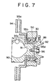
- a hub 88 includes two members 90,92.
- a brake disk 94 has radiating gaps 95a, and is provided integrally with a cylindrical connecting portion 95b and a larger-diameter portion 95c.
- the brake disk 94 is further provided with a contact portion 95d united with the connecting portion 95b.
- the connecting portion 95b of the brake disk 94 is press fitted to the member 90, then the contact portion 95d is brought into closely contact with both members 90,92 to be sandwiched between both members 90, 92, and then bolts 96 are screwed.
- the hub 88 is constituted and simultaneously the brake disk 94 is attached to the hub 88.
- Radial grooves (not shown) are provided on each of the confronting surfaces of the contact portion 95d of the brake disk 94 and the respective members 90,92 to restrict the rotary direction.
- a supported portion 91 is formed to be rotatably supported by the wheel carrier 30 through the bearing 50.
- a portion of the member 92 located more laterally outward of the vehicle body than the supported portion 91 functions as a disk wheel mounting portion, and the brake disk 94 is located more laterally inward of the vehicle body than the supported portion 91 of the hub 88.
- the brake disk is provided with the connecting portion, which is fitted to the supported portion of the hub, and the brake disk is located more laterally inward of the vehicle body than the supported portion. Also, the inner race of the bearing is press fitted to the connecting portion, and the hub is supported by the wheel carrier through the connecting portion of the brake disk and the bearing.
- the brake disk may be formed integrally with the hub so as to project from an end of the hub, and a portion of the hub located more laterally outward of the vehicle body than the brake disk is permitted to function as a supported portion to press fit the inner race of the bearing to the supported portion.
- the hub is supported by the wheel carrier through the bearing, so that the brake disk is located more laterally inward of the vehicle body than the supported portion.
- the brake disk 40 provided on the hub 38 is disposed more laterally inward of the vehicle body than the supported portion of the hub 38, i.e., at the center side of the vehicle body, so that a space 100 is ensured radially inward of a rim portion 75 of the disk wheel 74 of the wheel 32, as shown in Fig. 1.
- the portion 31b of the wheel carrier 30 below the supported portion is capable of being connected to the suspension arm 48 through the ball joint 47 disposed in the space 100.
- the rotary center O2 of the ball joint 47 is brought as outward as possible in the lateral direction of the vehicle body to permit the I-K distance to make smaller than the I-K distance in case of Fig. 9.
- the wheel carrier 30 has oblique portions 31d extending bifurcatedly upward from a portion 31c surrounding the supported portion of the hub, and a horizontal portion 31e extending from each portion 31d in the lateral direction of the vehicle body.
- the upper portion 31a extends upright from the horizontal portions 31e.
- Each of the oblique portions 31d is provided with a bracket 102, and a pin 104 is studed in each bracket 102.
- the brake caliper 36 of the structure known per se for generating a braking force in cooperation with the brake disk is slidably mounted to the pin 104, and pads 106 (See Fig. 1) are disposed so as to sandwich the brake disk 40. If the brake caliper 36 is disposed above the drive shaft 34 as shown in Fig. 1, the interference in steering of the brake caliper 36 with the drive shaft 34 is prevented.
- Fig. 4 shows an embodiment of a suspension of a double wishbone type, in which a wheel carrier 110 is swingably connected to the suspension arm 48 through the ball joint 47, and an upper portion of the wheel carrier 110 is swingably connected to a suspension arm 114 through a ball joint 112.
- the suspension arm 114 is swingably connected to a shock absorber 116.
- the steering axis L is provided as a straight line connecting the center O1 of the ball joint 112 with the center O2 of the ball joint 47.
- the hub 38 and the brake disk 40 in this embodiment are similar to those in the above-mentioned embodiment. Accordingly, the ball joint 47 is located more laterally outward of the vehicle body than the bake disk 40, and the I-K distance is made small. If an upper portion 111 of the wheel carrier 110 is so formed to project outward as shown in this embodiment, the I-K distance is made smaller.
- Fig. 8 shows another embodiment of a suspension of a double wishbone type.
- the wheel carrier 110 in this embodiment is substantially similar to that shown in Fig. 4, and an upper portion 111a of the wheel carrier 110 is swingably connected to an upper suspension arm 120 through a ball joint 122.
- the suspension arm 120 takes the V or A-like plane shape, and is connected swingably around a longitudinally extending axis to the vehicle body through a bushing 124 mounted to each of two inward ends 121 longitudinally disposed at an interval.
- the wheel carrier 110 has a lower portion 111b rotatably connected to a shaft portion 127 of a connection arm 126.
- the line connecting an axis of the shaft portion 127 with the center of the ball joint 122 is coincident with the steering axis L, so that the steering operation is ensured by the shaft portion 127.
- the connection arm 126 is swingably connected to a suspension arm 130 through a joint 128 having a longitudinally extending axis. The bound and rebound are ensured by the joint 128.
- the suspension arm 130 takes the V or A-like plane shape, and is connected swingably around a longitudinally extending axis to the vehicle body through a bushing 132 mounted to each of two inward ends 131 longitudinally disposed at an interval.
- a hub 138 includes two members 140,142, which are joined together by bolts 144.
- the member 140 serves as the casing of the constant velocity joint, and the shaft 34 is connected to the member 140.
- the member 142 has a supported portion 143 rotatably supported by the wheel carrier 110 through the bearing 50. Then, the disk wheel 74 of the wheel 32 is mounted to a portion of the member 142 located laterally outward of the vehicle body than the supported portion 143 by the bolts 76.
- a brake disk 146 has radiating gaps 147a, and is provided with an annular connecting portion 147b.
- the annular connecting portion 147b is sandwiched between the members 140,142, and the brake disk 146 is attached to the hub 138 by the bolts 144.
- connection arm 126 does not move relative to the wheel carrier 110, the connection arm 126 can be positioned as close as possible to the brake disk 146.
- a suspension for a steerable driving wheel in a vehicle in which a wheel (32) supported by a wheel carrier (30) rotatable around a steering axis (L) is driven by a drive shaft (34) and braked by a brake caliper (36), includes a hub (38) and a brake disk (40).
- the hub (38) has a supported portion (39a) rotatably supported by the wheel carrier (30) through a bearing (50) and is unrotatably connected to the drive shaft (34).
- the hub (38) attaches the wheel (32) to a portion (39b) located more laterally outward of a vehicle body than the supported portion (39a).
- the brake disk (40) for generating a braking force in cooperation with the brake caliper (36) is provided on the hub (38) and disposed more laterally inward of the vehicle body than said supported portion (39a).
Landscapes
- Engineering & Computer Science (AREA)
- Mechanical Engineering (AREA)
- Transportation (AREA)
- Vehicle Body Suspensions (AREA)
- Braking Arrangements (AREA)
Priority Applications (1)
| Application Number | Priority Date | Filing Date | Title |
|---|---|---|---|
| EP93110616A EP0572041B1 (de) | 1989-06-13 | 1990-06-07 | Radaufhängung für ein lenkbares, angetriebenes Fahrzeugrad |
Applications Claiming Priority (2)
| Application Number | Priority Date | Filing Date | Title |
|---|---|---|---|
| JP150139/89 | 1989-06-13 | ||
| JP15013989 | 1989-06-13 |
Related Child Applications (1)
| Application Number | Title | Priority Date | Filing Date |
|---|---|---|---|
| EP93110616.5 Division-Into | 1993-07-02 |
Publications (2)
| Publication Number | Publication Date |
|---|---|
| EP0402777A1 true EP0402777A1 (de) | 1990-12-19 |
| EP0402777B1 EP0402777B1 (de) | 1994-02-16 |
Family
ID=15490345
Family Applications (2)
| Application Number | Title | Priority Date | Filing Date |
|---|---|---|---|
| EP93110616A Expired - Lifetime EP0572041B1 (de) | 1989-06-13 | 1990-06-07 | Radaufhängung für ein lenkbares, angetriebenes Fahrzeugrad |
| EP90110843A Expired - Lifetime EP0402777B1 (de) | 1989-06-13 | 1990-06-07 | Radaufhängung für ein lenkbares, angetriebenes Fahrzeugrad |
Family Applications Before (1)
| Application Number | Title | Priority Date | Filing Date |
|---|---|---|---|
| EP93110616A Expired - Lifetime EP0572041B1 (de) | 1989-06-13 | 1990-06-07 | Radaufhängung für ein lenkbares, angetriebenes Fahrzeugrad |
Country Status (4)
| Country | Link |
|---|---|
| US (1) | US5048859A (de) |
| EP (2) | EP0572041B1 (de) |
| JP (1) | JPH03104719A (de) |
| DE (2) | DE69006642T2 (de) |
Cited By (7)
| Publication number | Priority date | Publication date | Assignee | Title |
|---|---|---|---|---|
| US5382044A (en) * | 1992-12-17 | 1995-01-17 | Chrysler Corporation | Mounting structure of a front suspension system |
| EP0906840A3 (de) * | 1997-10-04 | 2000-08-30 | Otto Sauer Achsenfabrik Keilberg | Achsaufhängung für Fahrzeuge |
| EP1582438A1 (de) * | 2004-04-01 | 2005-10-05 | Ford Global Technologies, LLC | Gerät für eine lenkbare Aufhängung eines Fahrzeugrades |
| EP1983209A2 (de) | 2007-04-20 | 2008-10-22 | Deere & Company | Integrierte Außenbord-Nassscheibenbremse |
| DE102010031054A1 (de) | 2010-07-07 | 2012-01-12 | Bayerische Motoren Werke Aktiengesellschaft | Dämpferbein-Achse der Eingelenk-Bauart |
| US10124639B2 (en) | 2013-11-05 | 2018-11-13 | Brist Axle Systems S.R.L. | Wheel suspension for a motor vehicle |
| US12023980B2 (en) * | 2022-08-24 | 2024-07-02 | Hyundai Mobis Co., Ltd. | Suspension apparatus for vehicle |
Families Citing this family (26)
| Publication number | Priority date | Publication date | Assignee | Title |
|---|---|---|---|---|
| US5215329A (en) * | 1990-11-22 | 1993-06-01 | Toyota Jidosha Kabushiki Kaisha | Twist beam type rear suspension reinforced against side force with longitudinal compliance |
| US5180180A (en) * | 1991-04-24 | 1993-01-19 | Aisin Aw Co., Ltd. | Wheel supporting apparatus |
| DE19525084A1 (de) * | 1995-07-10 | 1996-08-29 | Daimler Benz Ag | Kugelgelenk bei Hochlenkerachsen von Kraftfahrzeugen für die Anlenkung eines oberen Querlenkers an den Radträger |
| US6223863B1 (en) * | 1996-12-12 | 2001-05-01 | Federal-Mogul Technology Limited | Disc brake suspension for improved turning circle |
| IT1291044B1 (it) * | 1997-02-21 | 1998-12-14 | Skf Ind Spa | Configurazione per l'accoppiamento del freno al gruppo cuscinetto/ mozzo di una ruota di veicolo. |
| JPH11129717A (ja) * | 1997-10-31 | 1999-05-18 | Nissan Motor Co Ltd | フロントサスペンション装置 |
| JP4162804B2 (ja) * | 1998-07-31 | 2008-10-08 | 中央発條株式会社 | ストラット型懸架装置 |
| US6079700A (en) * | 1998-10-09 | 2000-06-27 | Chrysler Corporation | Vehicle shock absorber spring seat pad having a spring--containment peripheral flange |
| US6155543A (en) * | 1999-01-27 | 2000-12-05 | Daimlerchrysler Corporation | Spring seat assembly for an automotive vehicle |
| GB9902598D0 (en) | 1999-02-06 | 1999-03-24 | Rover Group | A suspension arrangement |
| US20040050631A1 (en) * | 2002-09-12 | 2004-03-18 | Booher Benjamin V. | Quick change combination wheel and brake assembly |
| JP4133186B2 (ja) * | 2002-10-02 | 2008-08-13 | 株式会社ブリヂストン | 操舵輪用インホイールモータシステム |
| US7185902B1 (en) | 2003-03-14 | 2007-03-06 | Altair Engineering, Inc. | Strut suspension with pivoting rocker arm |
| ITTO20040319A1 (it) * | 2004-05-14 | 2004-08-14 | Skf Ab | Montante per veicoli |
| JP2006088962A (ja) * | 2004-09-27 | 2006-04-06 | Toyota Motor Corp | ストラット式サスペンション |
| DE102005034149B3 (de) * | 2005-07-19 | 2007-03-08 | Zf Friedrichshafen Ag | Messvorrichtung für ein Kraftfahrzeug |
| US7815030B2 (en) * | 2006-04-03 | 2010-10-19 | Eaton Corporation | Key hole slots for cushioned ceramic driven disc assembly incorporating direct bond cushioned ceramic facings |
| JP4939310B2 (ja) * | 2007-06-07 | 2012-05-23 | 本田技研工業株式会社 | ストラット式サスペンション装置 |
| DE102008003646A1 (de) | 2008-01-09 | 2009-07-16 | GM Global Technology Operations, Inc., Detroit | Radnabengelenkeinheit für ein Fahrzeug |
| US20090297084A1 (en) * | 2008-05-29 | 2009-12-03 | Ziech James F | Preset wheel bearing arrangement |
| DE102011015011A1 (de) * | 2011-03-25 | 2012-09-27 | GM Global Technology Operations LLC (n. d. Gesetzen des Staates Delaware) | Lager, Fahrzeug sowie Verfahren zum Montieren eines Fahrzeugs |
| KR101361287B1 (ko) * | 2012-05-15 | 2014-02-12 | 현대자동차주식회사 | 차량용 서스펜션 암 연결 장치 |
| DE102013222443A1 (de) | 2013-11-05 | 2015-05-07 | Voith Patent Gmbh | Radaufhängung für ein Kraftfahrzeug |
| ITUA20163542A1 (it) * | 2016-05-18 | 2017-11-18 | Brist Axle Systems S R L | Sospensione indipendente per veicoli, in particolare una sospensione per una ruota sterzante di veicoli |
| US10065471B2 (en) * | 2017-01-31 | 2018-09-04 | Nhk Spring Co., Ltd. | Coil spring for vehicle suspension |
| DE102019003022B4 (de) | 2019-04-29 | 2022-09-29 | Trw Automotive Gmbh | Einzelradaufhängung |
Citations (4)
| Publication number | Priority date | Publication date | Assignee | Title |
|---|---|---|---|---|
| DE2233391A1 (de) * | 1972-07-07 | 1974-01-24 | Teves Gmbh Alfred | Radaufhaengung fuer die gelenkten raeder von fahrzeugen |
| DE2348849A1 (de) * | 1973-09-28 | 1975-04-10 | Teves Gmbh Alfred | Radaufhaengung mit negativem lenkrollradius |
| GB2130979A (en) * | 1982-11-24 | 1984-06-13 | Honda Motor Co Ltd | Vehicle suspensions |
| EP0253384A2 (de) * | 1986-07-15 | 1988-01-20 | Nissan Motor Co., Ltd. | Aufhängungssystem vom Typ mit zwei Aufhängungsarmen |
Family Cites Families (4)
| Publication number | Priority date | Publication date | Assignee | Title |
|---|---|---|---|---|
| US3757883A (en) * | 1971-02-03 | 1973-09-11 | Skf Nv | Wheel support for an engine propelled road vehicle |
| JPS6164506A (ja) * | 1984-09-05 | 1986-04-02 | Nissan Motor Co Ltd | ストラツト型サスペンシヨン |
| JPS63101338U (de) * | 1986-12-19 | 1988-07-01 | ||
| JPH0625362Y2 (ja) * | 1987-10-23 | 1994-07-06 | トヨタ自動車株式会社 | 車両用サスペンシヨンのアライメント調整装置 |
-
1989
- 1989-11-09 JP JP1290113A patent/JPH03104719A/ja active Pending
-
1990
- 1990-05-30 US US07/530,781 patent/US5048859A/en not_active Expired - Fee Related
- 1990-06-07 DE DE69006642T patent/DE69006642T2/de not_active Expired - Fee Related
- 1990-06-07 DE DE69028558T patent/DE69028558T2/de not_active Expired - Fee Related
- 1990-06-07 EP EP93110616A patent/EP0572041B1/de not_active Expired - Lifetime
- 1990-06-07 EP EP90110843A patent/EP0402777B1/de not_active Expired - Lifetime
Patent Citations (4)
| Publication number | Priority date | Publication date | Assignee | Title |
|---|---|---|---|---|
| DE2233391A1 (de) * | 1972-07-07 | 1974-01-24 | Teves Gmbh Alfred | Radaufhaengung fuer die gelenkten raeder von fahrzeugen |
| DE2348849A1 (de) * | 1973-09-28 | 1975-04-10 | Teves Gmbh Alfred | Radaufhaengung mit negativem lenkrollradius |
| GB2130979A (en) * | 1982-11-24 | 1984-06-13 | Honda Motor Co Ltd | Vehicle suspensions |
| EP0253384A2 (de) * | 1986-07-15 | 1988-01-20 | Nissan Motor Co., Ltd. | Aufhängungssystem vom Typ mit zwei Aufhängungsarmen |
Cited By (14)
| Publication number | Priority date | Publication date | Assignee | Title |
|---|---|---|---|---|
| US5382044A (en) * | 1992-12-17 | 1995-01-17 | Chrysler Corporation | Mounting structure of a front suspension system |
| EP0906840A3 (de) * | 1997-10-04 | 2000-08-30 | Otto Sauer Achsenfabrik Keilberg | Achsaufhängung für Fahrzeuge |
| US6322089B1 (en) | 1997-10-04 | 2001-11-27 | Otto Sauer Achsenfabrik Keilberg | Suspension for motor vehicles |
| EP1582438A1 (de) * | 2004-04-01 | 2005-10-05 | Ford Global Technologies, LLC | Gerät für eine lenkbare Aufhängung eines Fahrzeugrades |
| US8256583B2 (en) | 2007-04-20 | 2012-09-04 | Deere & Company | Integrated outboard wet disk brake |
| EP1983209A2 (de) | 2007-04-20 | 2008-10-22 | Deere & Company | Integrierte Außenbord-Nassscheibenbremse |
| EP1983209A3 (de) * | 2007-04-20 | 2010-07-21 | Deere & Company | Integrierte Außenbord-Nassscheibenbremse |
| DE102010031054A1 (de) | 2010-07-07 | 2012-01-12 | Bayerische Motoren Werke Aktiengesellschaft | Dämpferbein-Achse der Eingelenk-Bauart |
| WO2012004061A1 (de) | 2010-07-07 | 2012-01-12 | Bayerische Motoren Werke Aktiengesellschaft | Dämpferbein-achse der eingelenk-bauart |
| CN102858561A (zh) * | 2010-07-07 | 2013-01-02 | 宝马股份公司 | 单铰链结构型式的减震支柱-轴 |
| US8777244B2 (en) | 2010-07-07 | 2014-07-15 | Bayerische Motoren Werke Aktiengesellschaft | Single-pivot type suspension strut axle |
| CN102858561B (zh) * | 2010-07-07 | 2015-09-16 | 宝马股份公司 | 车轮悬架装置 |
| US10124639B2 (en) | 2013-11-05 | 2018-11-13 | Brist Axle Systems S.R.L. | Wheel suspension for a motor vehicle |
| US12023980B2 (en) * | 2022-08-24 | 2024-07-02 | Hyundai Mobis Co., Ltd. | Suspension apparatus for vehicle |
Also Published As
| Publication number | Publication date |
|---|---|
| EP0572041B1 (de) | 1996-09-11 |
| DE69028558D1 (de) | 1996-10-17 |
| US5048859A (en) | 1991-09-17 |
| DE69028558T2 (de) | 1997-02-06 |
| DE69006642D1 (de) | 1994-03-24 |
| DE69006642T2 (de) | 1994-06-23 |
| JPH03104719A (ja) | 1991-05-01 |
| EP0402777B1 (de) | 1994-02-16 |
| EP0572041A1 (de) | 1993-12-01 |
Similar Documents
| Publication | Publication Date | Title |
|---|---|---|
| US5048859A (en) | Suspension for steerable driving wheel in vehicle | |
| JP4149134B2 (ja) | ホイールサスペンションアセンブリ | |
| US7441788B2 (en) | Front drive geometry for an all-terrain vehicle | |
| US5984422A (en) | Inboard mounted wheel end disconnect unit | |
| JPS6034481Y2 (ja) | 車輛用車輪支持機構 | |
| US4802688A (en) | Double link type suspension system | |
| JP4200938B2 (ja) | 電動輪 | |
| JP2005014729A (ja) | 車両用懸架装置 | |
| JP2007154938A (ja) | ストラット式サスペンション | |
| US20030159894A1 (en) | Wheel mounting | |
| JPH01106713A (ja) | ダブルリンク式サスペンション装置 | |
| JP3255915B2 (ja) | 車 軸 | |
| JP7362781B2 (ja) | 商用車のステアリングナックル、商用車の車軸アセンブリおよび車両車軸 | |
| JPS62188815A (ja) | 車輪軸受ユニツト | |
| JPH03502084A (ja) | 特殊表面用の自動またはトラクター索引車両 | |
| CN223407748U (zh) | 一种越野拉力赛车用前悬挂系统 | |
| JPH06503407A (ja) | ディスクブレーキの外側横断面が非円形のホイールハブ | |
| JP2993190B2 (ja) | 車両の駆動装置 | |
| JPH0632245A (ja) | サスペンションのアライメント調整構造 | |
| JPH05193513A (ja) | 操舵装置 | |
| JP2691724B2 (ja) | 車両用車輪並びにこの車輪を用いたサスペンション装置及びステアリング装置 | |
| JPH0724241Y2 (ja) | 自動車の車輪駆動装置 | |
| JP3267132B2 (ja) | アクスル構造 | |
| US20250277513A1 (en) | Axle assembly and off-road vehicle | |
| JPS6311163B2 (de) |
Legal Events
| Date | Code | Title | Description |
|---|---|---|---|
| PUAI | Public reference made under article 153(3) epc to a published international application that has entered the european phase |
Free format text: ORIGINAL CODE: 0009012 |
|
| 17P | Request for examination filed |
Effective date: 19900607 |
|
| AK | Designated contracting states |
Kind code of ref document: A1 Designated state(s): DE FR GB |
|
| 17Q | First examination report despatched |
Effective date: 19920909 |
|
| GRAA | (expected) grant |
Free format text: ORIGINAL CODE: 0009210 |
|
| AK | Designated contracting states |
Kind code of ref document: B1 Designated state(s): DE FR GB |
|
| XX | Miscellaneous (additional remarks) |
Free format text: TEILANMELDUNG 93110616.5 EINGEREICHT AM 07/06/90. |
|
| REF | Corresponds to: |
Ref document number: 69006642 Country of ref document: DE Date of ref document: 19940324 |
|
| ET | Fr: translation filed | ||
| RIN2 | Information on inventor provided after grant (corrected) |
Free format text: NISHIKUMA, YASUSHI * KAWAKAMI, SEIHO * ITOGA, KAZUKIYO * MAE, SHIGENORI * SANTO, TOSHIYASU |
|
| PLBE | No opposition filed within time limit |
Free format text: ORIGINAL CODE: 0009261 |
|
| STAA | Information on the status of an ep patent application or granted ep patent |
Free format text: STATUS: NO OPPOSITION FILED WITHIN TIME LIMIT |
|
| 26N | No opposition filed | ||
| PGFP | Annual fee paid to national office [announced via postgrant information from national office to epo] |
Ref country code: GB Payment date: 19970529 Year of fee payment: 8 |
|
| PGFP | Annual fee paid to national office [announced via postgrant information from national office to epo] |
Ref country code: FR Payment date: 19970610 Year of fee payment: 8 |
|
| PGFP | Annual fee paid to national office [announced via postgrant information from national office to epo] |
Ref country code: DE Payment date: 19970613 Year of fee payment: 8 |
|
| PG25 | Lapsed in a contracting state [announced via postgrant information from national office to epo] |
Ref country code: GB Free format text: LAPSE BECAUSE OF NON-PAYMENT OF DUE FEES Effective date: 19980607 |
|
| GBPC | Gb: european patent ceased through non-payment of renewal fee |
Effective date: 19980607 |
|
| PG25 | Lapsed in a contracting state [announced via postgrant information from national office to epo] |
Ref country code: FR Free format text: LAPSE BECAUSE OF NON-PAYMENT OF DUE FEES Effective date: 19990226 |
|
| PG25 | Lapsed in a contracting state [announced via postgrant information from national office to epo] |
Ref country code: DE Free format text: LAPSE BECAUSE OF NON-PAYMENT OF DUE FEES Effective date: 19990401 |
|
| REG | Reference to a national code |
Ref country code: FR Ref legal event code: ST |