EP0403219B1 - Tube à rayons cathodiques en couleurs - Google Patents
Tube à rayons cathodiques en couleurs Download PDFInfo
- Publication number
- EP0403219B1 EP0403219B1 EP90306375A EP90306375A EP0403219B1 EP 0403219 B1 EP0403219 B1 EP 0403219B1 EP 90306375 A EP90306375 A EP 90306375A EP 90306375 A EP90306375 A EP 90306375A EP 0403219 B1 EP0403219 B1 EP 0403219B1
- Authority
- EP
- European Patent Office
- Prior art keywords
- tungsten
- shadow mask
- film
- ray tube
- cathode ray
- Prior art date
- Legal status (The legal status is an assumption and is not a legal conclusion. Google has not performed a legal analysis and makes no representation as to the accuracy of the status listed.)
- Expired - Lifetime
Links
Images


Classifications
-
- H—ELECTRICITY
- H01—ELECTRIC ELEMENTS
- H01J—ELECTRIC DISCHARGE TUBES OR DISCHARGE LAMPS
- H01J29/00—Details of cathode-ray tubes or of electron-beam tubes of the types covered by group H01J31/00
- H01J29/02—Electrodes; Screens; Mounting, supporting, spacing or insulating thereof
- H01J29/06—Screens for shielding; Masks interposed in the electron stream
- H01J29/07—Shadow masks for colour television tubes
-
- H—ELECTRICITY
- H01—ELECTRIC ELEMENTS
- H01J—ELECTRIC DISCHARGE TUBES OR DISCHARGE LAMPS
- H01J9/00—Apparatus or processes specially adapted for the manufacture, installation, removal, maintenance of electric discharge tubes, discharge lamps, or parts thereof; Recovery of material from discharge tubes or lamps
- H01J9/02—Manufacture of electrodes or electrode systems
- H01J9/14—Manufacture of electrodes or electrode systems of non-emitting electrodes
- H01J9/142—Manufacture of electrodes or electrode systems of non-emitting electrodes of shadow-masks for colour television tubes
- H01J9/146—Surface treatment, e.g. blackening, coating
-
- H—ELECTRICITY
- H01—ELECTRIC ELEMENTS
- H01J—ELECTRIC DISCHARGE TUBES OR DISCHARGE LAMPS
- H01J2229/00—Details of cathode ray tubes or electron beam tubes
- H01J2229/07—Shadow masks
- H01J2229/0727—Aperture plate
- H01J2229/0777—Coatings
Definitions
- the present invention relates to a color cathode ray tube and, more particularly, to a technique for preventing a doming effect in which a shadow mask deforms because a temperature of the shadow mask is increased by thermal energy generated by collision of an electron beam emitted from an electron gun, causing color dislocation in a picture.
- a conventional color cathode ray tube is disclosed in, for example Japanese Patent Laid Open Gazette No. 55-76553, in which an electron beam reflecting film comprising bismuth oxide (Bi2O3) as a main element and binder such as water glass mixed therein is formed on an electron beam irradiated surface of a shadow mask.
- an electron beam reflecting film comprising bismuth oxide (Bi2O3) as a main element and binder such as water glass mixed therein is formed on an electron beam irradiated surface of a shadow mask.
- an anti-doming effect obtained by the electron reflecting film formed on the shadow mask is approximately 30%, which is not sufficient for a large sized color cathode ray tube.
- a film comprising metal tungsten as a main element is formed on a surface of the shadow mask instead of the film comprising Bi2O3 as a main element.
- the anti-doming effect can be 50% in theory.
- performance of the film can be improved by 50% or more as compared with that of the film comprising Bi2O3 as a main element.
- U.S. Patent No. 4 442 376 discloses a colour display tube having a shadow mask positioned in front of a display screen.
- the shadow mask is coated at least on the side remote from the display screen with a heavy metal layer of selectively varied thickness.
- the heavy metal has an atomic number exceeding 70 and has a high electron reflection coefficient, thus minimizing energy absorbed by the shadow mask from electrons impinging on the mask.
- a method of preventing doming in a colour cathode ray tube shadow mask due to irradiation thereof during use including the steps of:- applying a mixture of tungsten particles and a binder to the surface of a shadow mask preform; and driving off said binder by baking; characterised in that said particles are coated with a material that is more readily oxidisable than tungsten, and that is active to form an oxide that shall limit or prevent further oxidation of said tungsten particles during baking.
- the material likely to be more readily oxidizable than tungsten, is magnesium, aluminium, a 4A group element, silicon, vanadium, manganese or molybdenum or any of these in combination.
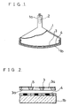
- Figure 1 is a partially broken side view showing a color cathode ray tube in accordance with an embodiment of the present invention.
- reference numeral 1 designates an outer frame for keeping its inside highly vacuous
- reference numeral 2 designates an electron gun built in a neck part la of the outer frame, which emits an electron beam toward a translucent glass panel part 1b serving as a part of the outer frame 1.
- Reference numeral 3 designates a shadow mask formed of a thin iron plate, in which a number of through holes 3a for electron beams are formed as shown in Figure 2.
- Reference numeral 4 designates a fluorescent screen on which three kinds of stripes of fluorescent materials emitting red, green and blue light are applied to an inner surface of the glass panel lb. These stripes of the fluorescent materials are arranged so as to each correspond to each of the electron beam through holes 3a in the shadow mask 3 in an electronic optical manner.
- an electron beam reflecting film 5 comprising tungsten having large reflection coefficient to the electron beam, as a main component is formed on the side of the electron beam irradiated surface of the shadow mask 3 as shown in Figure 2.
- the film may be formed of tungsten powder which are coated with 50 to 10000 ppm of one or more kinds of metals selected from a group of magnesium, aluminum, 4A group element, silicon, vanadium, or molybdenum prior to a baking process.
- Three electron beams emitted from the electron gun 2 are deflected so as to scan the whole surface of the fluorescent screen 4 by a deflecting apparatus (not shown) and then reach the shadow mask 3.
- the three electron beams pass through the electron beam through holes 3a of the shadow mask 3 and hit the stripes of the fluorescent materials on the fluorescent screen 4 to make them emit light, with the result that a color picture is projected on the fluorescent screen 4.
- Tungsten powder to which silver is coated through chemical treatment (silver concentration is 6000 ppm) was sprayed on the shadow mask until this thickness became 10 »m (microns) and then baked at a temperature of 450°C for 30 minutes in the air.
- the thus formed film was subjected to X-ray diffraction.
- a material (WO3) produced by oxidation is confirmed by a diffraction peak around a diffraction angle of 23.28 degrees
- a product material (WO 2.9 ) is confirmed by a diffraction peak around that of 33 degrees and that of 37 degrees.
- a diffraction peak of metal tungsten (W) was around a diffraction angle of 40 degrees.
- the shadow mask on which the film was formed of tungsten powder coated in silver as described above was built in a 64 cm (25-inch) color CRT and then an anti-doming effect was measured. As a result, it was found that the anti-doming effect was 50%.
- a film with a thickness of 7 »m (microns) was formed on a shadow mask surface using tungsten powder alloyed by adding palladium (Pd) to tungsten by 500 ppm and then it was baked in the air. Then, this shadow mask was built in a 74 cm (29-inch) color CRT and then an anti-doming effect was measured. As a result, it was found that the anti-doming effect was 49%.
- Figure 5 shows a result of X-ray diffraction of a film with a thickness of 10 »m (microns) which was formed using tungsten powder alloyed by adding molybdenum (Mo) to tungsten by 100 ppm and it was baked in the same condition as in the Example 1.
- Mo molybdenum
- metal tungsten also sufficiently remained in this Example 3 and the ratio of it was almost equal to that of produced oxide (WO3). More specifically, it was found that molybdenum (Mo) had a practically enough anti-oxidation effect even if concentration of molybdenum was not so high.
- the shadow mask in accordance with the Example 3 was built in a 64 cm (25-inch) color CRT and then the anti-doming effect was measured. As a result, it was found that the anti-doming effect was 48%.
- a film with a thickness of 15 »m was formed on a shadow mask surface using tungsten powder coated by aluminum (A1) in concentration of 10000 ppm and then it was baked in the air. Then, this was built in the 74 cm (29-inch) color CRT and then the anti-doming effect was measured. As a result, it was found that the anti-doming effect was 48%.
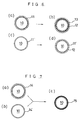
- Figure 6 is a schematic view showing an example by way of reference in which the tungsten in the above described Examples 1 and 2 is coated with metal which is less likely to be oxidized than tungsten (not falling within the scope of the claims).
- Figure 6(a) shows the state where fine-grain silver 11 is coated on the tungsten
- Figure 6(c) shows the state where uniform coating layer is formed on the surface of the tungsten 10 using fine-grain silver 11' whose grains are smaller than those of silver 11
- Figures 6(b) and 6(d) show the state of tungsten of Figures 6(a) and 6(c) after baking, respectively.
- Figure 7 is a schematic view showing the state where tungsten in the above described Examples 3 and 4 is coated according to the invention with metal which is more likely to be oxidized than tungsten.
- Figures 7(a) and 7(b) show the state where tungsten 10 is coated with aluminum either in the form of particles or uniformly (respectively 14, 14′) in the same way as above described embodiment, and
- Figure 7(c) shows the state of tungsten of Figure 7(a) and 7(b) after baking, in both cases the surface of tungsten 10 is a little oxidized and aluminum 14 and 14′ become alumina, Al2O3 15.
- oxidation of tungsten can be prevented by adding a small amount only of metal, which is not likely to be oxidized as compared with tungsten (not falling within the scope of the claims), to tungsten which is likely to be oxidized, even when normal manufacturing process in which a film is baked in the air is used.
- the anti-doming effect can be fairly improved, while manufacturing costs are almost the same as when a film is formed of Bi2O3 in a conventional manner.
- a stable oxide layer can be promptly formed on a surface of tungsten powder by coating according to the invention with a material which is more likely to be oxidized as compared with tungsten so that thermal oxidation of tungsten powder itself can be prevented.
- the anti-doming effect of the film comprising tungsten as a main element can be fairly improved.
Landscapes
- Engineering & Computer Science (AREA)
- Manufacturing & Machinery (AREA)
- Electrodes For Cathode-Ray Tubes (AREA)
- Vessels, Lead-In Wires, Accessory Apparatuses For Cathode-Ray Tubes (AREA)
Claims (2)
- Un procédé de prévention de la formation de dôme dans un masque perforé de tube cathodique en couleurs, sous l'effet de l'irradiation de ce masque pendant l'utilisation, comprenant les étapes suivantes :
on applique sur la surface d'une préforme de masque perforé un mélange de particules de tungstène et d'un liant; et
on chasse le liant par cuisson;
caractérisé en ce que les particules sont revêtues avec une matière qui est plus aisément oxydable que le tungstène, et qui forme un oxyde qui limitera ou empêchera une oxydation ultérieure des particules de tungstène pendant la cuisson. - Un procédé selon la revendication 1, caractérisé en ce que la matière précitée, susceptible d'être plus aisément oxydable que le tungstène, est du magnésium, de l'aluminium, un élément du groupe 4A, du silicium, du vanadium, du manganèse ou du molybdène, ou une combinaison quelconque de ces éléments.
Applications Claiming Priority (2)
| Application Number | Priority Date | Filing Date | Title |
|---|---|---|---|
| JP1154914A JPH0320934A (ja) | 1989-06-15 | 1989-06-15 | カラー陰極線管 |
| JP154914/89 | 1989-06-15 |
Publications (2)
| Publication Number | Publication Date |
|---|---|
| EP0403219A1 EP0403219A1 (fr) | 1990-12-19 |
| EP0403219B1 true EP0403219B1 (fr) | 1995-04-12 |
Family
ID=15594720
Family Applications (1)
| Application Number | Title | Priority Date | Filing Date |
|---|---|---|---|
| EP90306375A Expired - Lifetime EP0403219B1 (fr) | 1989-06-15 | 1990-06-12 | Tube à rayons cathodiques en couleurs |
Country Status (5)
| Country | Link |
|---|---|
| US (1) | US5256932A (fr) |
| EP (1) | EP0403219B1 (fr) |
| JP (1) | JPH0320934A (fr) |
| KR (1) | KR920010659B1 (fr) |
| DE (1) | DE69018520T2 (fr) |
Families Citing this family (7)
| Publication number | Priority date | Publication date | Assignee | Title |
|---|---|---|---|---|
| US5451833A (en) * | 1993-10-28 | 1995-09-19 | Chunghwa Picture Tubes, Ltd. | Shadow mask damping for color CRT |
| JPH07254373A (ja) * | 1994-01-26 | 1995-10-03 | Toshiba Corp | カラー受像管及びその製造方法 |
| CN1060584C (zh) * | 1995-05-02 | 2001-01-10 | 中华映管股份有限公司 | 一种荫罩具有抗振动性能的阴极射线管 |
| DE19654613C2 (de) * | 1996-12-20 | 2001-07-19 | Samsung Display Devices Co Ltd | Schattenmaske mit Dämmschicht und Verfahren zu ihrer Herstellung |
| US6172449B1 (en) * | 1997-05-23 | 2001-01-09 | Matsushita Electric Industrial Co., Ltd. | Method of manufacturing electronic tube and electronic tube |
| KR100259300B1 (en) * | 1998-04-16 | 2000-06-15 | Lg Electronics Inc | Shadow mask for color cathode ray tube |
| DE10239863B4 (de) * | 2002-08-29 | 2005-03-17 | Webasto Ag | Fahrzeugdach mit einem über die Dachhaut nach hinten verschiebbaren Deckel |
Family Cites Families (9)
| Publication number | Priority date | Publication date | Assignee | Title |
|---|---|---|---|---|
| US3604970A (en) * | 1968-10-14 | 1971-09-14 | Varian Associates | Nonelectron emissive electrode structure utilizing ion-plated nonemissive coatings |
| JPS5576553A (en) * | 1978-12-05 | 1980-06-09 | Mitsubishi Electric Corp | Color braun tube |
| DE3125075C2 (de) * | 1980-07-16 | 1987-01-15 | N.V. Philips' Gloeilampenfabrieken, Eindhoven | Farbbildröhre |
| JPS616969A (ja) * | 1984-06-21 | 1986-01-13 | Fujitsu Ltd | 話頭切断防止方式 |
| JPH07118272B2 (ja) * | 1985-03-27 | 1995-12-18 | 株式会社東芝 | カラ−受像管 |
| JPS61273835A (ja) * | 1985-05-29 | 1986-12-04 | Mitsubishi Electric Corp | シヤドウマスクの製造方法 |
| US4734615A (en) * | 1985-07-17 | 1988-03-29 | Kabushiki Kaisha Toshiba | Color cathode ray tube |
| JPS62274525A (ja) * | 1986-05-22 | 1987-11-28 | Mitsubishi Electric Corp | シヤドウマスクの製造方法 |
| US4884004A (en) * | 1988-08-31 | 1989-11-28 | Rca Licensing Corp. | Color cathode-ray tube having a heat dissipative, electron reflective coating on a color selection electrode |
-
1989
- 1989-06-15 JP JP1154914A patent/JPH0320934A/ja active Pending
-
1990
- 1990-06-04 KR KR1019900008184A patent/KR920010659B1/ko not_active Expired
- 1990-06-12 EP EP90306375A patent/EP0403219B1/fr not_active Expired - Lifetime
- 1990-06-12 US US07/536,767 patent/US5256932A/en not_active Expired - Fee Related
- 1990-06-12 DE DE69018520T patent/DE69018520T2/de not_active Expired - Fee Related
Non-Patent Citations (1)
| Title |
|---|
| "Werkstoffkunde für die Electrotechnik und Elektronik", Hahn, Munke, Berlin 1986, page 465 * |
Also Published As
| Publication number | Publication date |
|---|---|
| KR910001852A (ko) | 1991-01-31 |
| US5256932A (en) | 1993-10-26 |
| DE69018520D1 (de) | 1995-05-18 |
| EP0403219A1 (fr) | 1990-12-19 |
| JPH0320934A (ja) | 1991-01-29 |
| KR920010659B1 (ko) | 1992-12-12 |
| DE69018520T2 (de) | 1995-09-14 |
Similar Documents
| Publication | Publication Date | Title |
|---|---|---|
| US4442376A (en) | Color display tube having heavy metal coating on color selection electrode | |
| EP0209346B1 (fr) | Procédé de fabrication d'un masque d'ombre | |
| EP0403219B1 (fr) | Tube à rayons cathodiques en couleurs | |
| US4884004A (en) | Color cathode-ray tube having a heat dissipative, electron reflective coating on a color selection electrode | |
| JP2746946B2 (ja) | カラー受像管 | |
| US6094003A (en) | Anti-doming composition for a shadow-mask and processes for preparing the same | |
| EP0392615B1 (fr) | Tube image couleur et dispositif de reproduction d'image comportant un tel tube image couleur | |
| JPH07118272B2 (ja) | カラ−受像管 | |
| US3721849A (en) | Dual persistence screen for a cathode ray tube | |
| US20020036455A1 (en) | Colour display tube with improved shadow mask | |
| JP3524207B2 (ja) | カラー受像管の製造方法 | |
| JPH0735284Y2 (ja) | ガス放電表示パネル | |
| JPH0668789A (ja) | カラー陰極線管の製造法 | |
| JPH0625876Y2 (ja) | ガス放電表示パネル | |
| JPS62188135A (ja) | カラ−受像管 | |
| JPH0766742B2 (ja) | ガス放電表示パネル | |
| JPH0714519A (ja) | カラー陰極線管およびその製造方法 | |
| JPH0622875Y2 (ja) | ガス放電表示装置 | |
| JPH06349417A (ja) | カラー陰極線管およびその製造方法 | |
| GB1584500A (en) | Cathode ray display tube with barrier layer penetration screen | |
| JPS61224245A (ja) | カラ−受像管 | |
| JPS62271325A (ja) | 陰極線管の製造方法 | |
| JPH0775145B2 (ja) | カラ−受像管 | |
| JPS6091534A (ja) | カラ−受像管の製造方法 | |
| JPH01194234A (ja) | カラー陰極線管の製造方法 |
Legal Events
| Date | Code | Title | Description |
|---|---|---|---|
| PUAI | Public reference made under article 153(3) epc to a published international application that has entered the european phase |
Free format text: ORIGINAL CODE: 0009012 |
|
| AK | Designated contracting states |
Kind code of ref document: A1 Designated state(s): DE FR NL |
|
| 17P | Request for examination filed |
Effective date: 19901228 |
|
| 17Q | First examination report despatched |
Effective date: 19930304 |
|
| GRAA | (expected) grant |
Free format text: ORIGINAL CODE: 0009210 |
|
| AK | Designated contracting states |
Kind code of ref document: B1 Designated state(s): DE FR NL |
|
| REF | Corresponds to: |
Ref document number: 69018520 Country of ref document: DE Date of ref document: 19950518 |
|
| PGFP | Annual fee paid to national office [announced via postgrant information from national office to epo] |
Ref country code: FR Payment date: 19950630 Year of fee payment: 6 |
|
| PGFP | Annual fee paid to national office [announced via postgrant information from national office to epo] |
Ref country code: DE Payment date: 19950703 Year of fee payment: 6 |
|
| ET | Fr: translation filed | ||
| PLBE | No opposition filed within time limit |
Free format text: ORIGINAL CODE: 0009261 |
|
| STAA | Information on the status of an ep patent application or granted ep patent |
Free format text: STATUS: NO OPPOSITION FILED WITHIN TIME LIMIT |
|
| 26N | No opposition filed | ||
| PGFP | Annual fee paid to national office [announced via postgrant information from national office to epo] |
Ref country code: NL Payment date: 19960630 Year of fee payment: 7 |
|
| PG25 | Lapsed in a contracting state [announced via postgrant information from national office to epo] |
Ref country code: FR Effective date: 19970228 |
|
| PG25 | Lapsed in a contracting state [announced via postgrant information from national office to epo] |
Ref country code: DE Effective date: 19970301 |
|
| REG | Reference to a national code |
Ref country code: FR Ref legal event code: ST |
|
| PG25 | Lapsed in a contracting state [announced via postgrant information from national office to epo] |
Ref country code: NL Effective date: 19980101 |
|
| NLV4 | Nl: lapsed or anulled due to non-payment of the annual fee |
Effective date: 19980101 |