EP0406584B1 - Capot de protection pour raccord médical - Google Patents
Capot de protection pour raccord médical Download PDFInfo
- Publication number
- EP0406584B1 EP0406584B1 EP19900110985 EP90110985A EP0406584B1 EP 0406584 B1 EP0406584 B1 EP 0406584B1 EP 19900110985 EP19900110985 EP 19900110985 EP 90110985 A EP90110985 A EP 90110985A EP 0406584 B1 EP0406584 B1 EP 0406584B1
- Authority
- EP
- European Patent Office
- Prior art keywords
- cap
- connector member
- connector
- open end
- cylindrical body
- Prior art date
- Legal status (The legal status is an assumption and is not a legal conclusion. Google has not performed a legal analysis and makes no representation as to the accuracy of the status listed.)
- Expired - Lifetime
Links
- 230000001954 sterilising effect Effects 0.000 claims description 19
- 238000004659 sterilization and disinfection Methods 0.000 claims description 19
- 229920005992 thermoplastic resin Polymers 0.000 claims description 4
- 238000000502 dialysis Methods 0.000 description 11
- 239000007788 liquid Substances 0.000 description 11
- 238000012856 packing Methods 0.000 description 8
- 244000005700 microbiome Species 0.000 description 7
- 210000000683 abdominal cavity Anatomy 0.000 description 6
- 238000003780 insertion Methods 0.000 description 6
- 230000037431 insertion Effects 0.000 description 6
- 238000000034 method Methods 0.000 description 6
- BZHJMEDXRYGGRV-UHFFFAOYSA-N Vinyl chloride Chemical compound ClC=C BZHJMEDXRYGGRV-UHFFFAOYSA-N 0.000 description 5
- 229920005989 resin Polymers 0.000 description 5
- 239000011347 resin Substances 0.000 description 5
- 238000002560 therapeutic procedure Methods 0.000 description 5
- WQZGKKKJIJFFOK-GASJEMHNSA-N Glucose Chemical compound OC[C@H]1OC(O)[C@H](O)[C@@H](O)[C@@H]1O WQZGKKKJIJFFOK-GASJEMHNSA-N 0.000 description 3
- 239000004743 Polypropylene Substances 0.000 description 3
- 229910010293 ceramic material Inorganic materials 0.000 description 3
- 238000010276 construction Methods 0.000 description 3
- 239000007769 metal material Substances 0.000 description 3
- 239000012466 permeate Substances 0.000 description 3
- -1 polypropylene Polymers 0.000 description 3
- 229920001155 polypropylene Polymers 0.000 description 3
- 229910000990 Ni alloy Inorganic materials 0.000 description 2
- PXHVJJICTQNCMI-UHFFFAOYSA-N Nickel Chemical compound [Ni] PXHVJJICTQNCMI-UHFFFAOYSA-N 0.000 description 2
- VYPSYNLAJGMNEJ-UHFFFAOYSA-N Silicium dioxide Chemical compound O=[Si]=O VYPSYNLAJGMNEJ-UHFFFAOYSA-N 0.000 description 2
- MCMNRKCIXSYSNV-UHFFFAOYSA-N Zirconium dioxide Chemical compound O=[Zr]=O MCMNRKCIXSYSNV-UHFFFAOYSA-N 0.000 description 2
- 238000004581 coalescence Methods 0.000 description 2
- 230000001939 inductive effect Effects 0.000 description 2
- 239000000463 material Substances 0.000 description 2
- 239000002184 metal Substances 0.000 description 2
- 229910052751 metal Inorganic materials 0.000 description 2
- 230000002265 prevention Effects 0.000 description 2
- 230000000717 retained effect Effects 0.000 description 2
- 238000007789 sealing Methods 0.000 description 2
- 241000894006 Bacteria Species 0.000 description 1
- 229910001369 Brass Inorganic materials 0.000 description 1
- LFQSCWFLJHTTHZ-UHFFFAOYSA-N Ethanol Chemical compound CCO LFQSCWFLJHTTHZ-UHFFFAOYSA-N 0.000 description 1
- IAYPIBMASNFSPL-UHFFFAOYSA-N Ethylene oxide Chemical compound C1CO1 IAYPIBMASNFSPL-UHFFFAOYSA-N 0.000 description 1
- 229910018487 Ni—Cr Inorganic materials 0.000 description 1
- 239000004698 Polyethylene Substances 0.000 description 1
- 239000004793 Polystyrene Substances 0.000 description 1
- 229910052581 Si3N4 Inorganic materials 0.000 description 1
- 229910001069 Ti alloy Inorganic materials 0.000 description 1
- 241000700605 Viruses Species 0.000 description 1
- PNEYBMLMFCGWSK-UHFFFAOYSA-N aluminium oxide Inorganic materials [O-2].[O-2].[O-2].[Al+3].[Al+3] PNEYBMLMFCGWSK-UHFFFAOYSA-N 0.000 description 1
- 230000000903 blocking effect Effects 0.000 description 1
- 239000008280 blood Substances 0.000 description 1
- 210000004369 blood Anatomy 0.000 description 1
- 239000010951 brass Substances 0.000 description 1
- 239000000919 ceramic Substances 0.000 description 1
- 238000009833 condensation Methods 0.000 description 1
- 230000005494 condensation Effects 0.000 description 1
- 238000011340 continuous therapy Methods 0.000 description 1
- 238000007796 conventional method Methods 0.000 description 1
- 238000010586 diagram Methods 0.000 description 1
- 230000000694 effects Effects 0.000 description 1
- 239000000706 filtrate Substances 0.000 description 1
- 229910052839 forsterite Inorganic materials 0.000 description 1
- 230000004927 fusion Effects 0.000 description 1
- 229920006015 heat resistant resin Polymers 0.000 description 1
- 210000003734 kidney Anatomy 0.000 description 1
- HCWCAKKEBCNQJP-UHFFFAOYSA-N magnesium orthosilicate Chemical compound [Mg+2].[Mg+2].[O-][Si]([O-])([O-])[O-] HCWCAKKEBCNQJP-UHFFFAOYSA-N 0.000 description 1
- 238000012423 maintenance Methods 0.000 description 1
- 150000002739 metals Chemical class 0.000 description 1
- 229910052759 nickel Inorganic materials 0.000 description 1
- 239000004745 nonwoven fabric Substances 0.000 description 1
- 210000004303 peritoneum Anatomy 0.000 description 1
- 206010034674 peritonitis Diseases 0.000 description 1
- 229920000573 polyethylene Polymers 0.000 description 1
- 229920002223 polystyrene Polymers 0.000 description 1
- 238000002360 preparation method Methods 0.000 description 1
- 238000000926 separation method Methods 0.000 description 1
- HBMJWWWQQXIZIP-UHFFFAOYSA-N silicon carbide Chemical compound [Si+]#[C-] HBMJWWWQQXIZIP-UHFFFAOYSA-N 0.000 description 1
- 229910010271 silicon carbide Inorganic materials 0.000 description 1
- 239000000377 silicon dioxide Substances 0.000 description 1
- HQVNEWCFYHHQES-UHFFFAOYSA-N silicon nitride Chemical compound N12[Si]34N5[Si]62N3[Si]51N64 HQVNEWCFYHHQES-UHFFFAOYSA-N 0.000 description 1
- 239000010935 stainless steel Substances 0.000 description 1
- 229910001220 stainless steel Inorganic materials 0.000 description 1
- 238000012360 testing method Methods 0.000 description 1
Images

Classifications
-
- A—HUMAN NECESSITIES
- A61—MEDICAL OR VETERINARY SCIENCE; HYGIENE
- A61M—DEVICES FOR INTRODUCING MEDIA INTO, OR ONTO, THE BODY; DEVICES FOR TRANSDUCING BODY MEDIA OR FOR TAKING MEDIA FROM THE BODY; DEVICES FOR PRODUCING OR ENDING SLEEP OR STUPOR
- A61M39/00—Tubes, tube connectors, tube couplings, valves, access sites or the like, specially adapted for medical use
- A61M39/20—Closure caps or plugs for connectors or open ends of tubes
-
- A—HUMAN NECESSITIES
- A61—MEDICAL OR VETERINARY SCIENCE; HYGIENE
- A61M—DEVICES FOR INTRODUCING MEDIA INTO, OR ONTO, THE BODY; DEVICES FOR TRANSDUCING BODY MEDIA OR FOR TAKING MEDIA FROM THE BODY; DEVICES FOR PRODUCING OR ENDING SLEEP OR STUPOR
- A61M39/00—Tubes, tube connectors, tube couplings, valves, access sites or the like, specially adapted for medical use
- A61M39/20—Closure caps or plugs for connectors or open ends of tubes
- A61M2039/205—Closure caps or plugs for connectors or open ends of tubes comprising air venting means
Definitions
- This invention relates to a cap for use with a medical tool connector as disclosed in claim 1. More particularly, it relates to a cap for use with such a medical tool connector as a connector of the type to be fitted to the leading end of a tube extended as a connector from a dialytic liquid bag which is used as in the method of peritoneal dialysis, for example.
- the latest therapy by peritoneal dialysis is such that the apparatus and tools to be used therefor are not voluminous and the cost incurred thereby is conspicuously small as compared with the dialysis resorting to an artificial kidney. Since the cause for peritoneal coalescence has been substantially elucidated, the peritoneal dialysis can be performed without inducing peritoneal coalescence. Moreover, the therapy itself has been developed to the extent of appreciably lowering the burden exerted on the patient. Further, the method of continuously applicable peritoneal dialysis (CAPD method) which allows the patient to take an uninterrupted treatment while continuing his work has been invented and employed widely for practical use. In these advantageous circumstances, this therapy has been reawakening interest and attracting attention.
- CPD method continuously applicable peritoneal dialysis
- a catheter is implanted in a patient's abdominal cavity and a connector member is attached the the extracorporeal end of the implanted catheter or the catheter having the connector member attached in advance thereto is wholly implanted in the patient's abdominal cavity.
- a connector member attached to the leading end of a tube of a dialytic liquid bag is connected to the connector member of the implanted catheter either directly or through the medium of a tube having connector members attached one each to the opposite ends thereof.
- the bag is suspended at a prescribed height higher than the abdominal cavity so that the dialytic liquid contained in the bag will flow down into the catheter and induce the dialysis aimed at.
- the two connector members for example, are sterilized with flame and connected to each other by shrinkage fit.
- the dialytic liquid bag is stowed in a packing container in conjunction with a dialytic liquid discharge tube attached to the bag and provided at the leading end thereof with a connector member and is preserved in a wholly sterilized state. Further, this connector member is designed so as to keep the tube in a thoroughly sterilized state even after the cap is attached thereto and the packing container is opened.
- the conventional cap for the connector is made of a heat-resistant corrosionproof metal, as illustrated in Fig. 4 and Fig. 5, in the shape of a blind cylindrical cap 5 provided at one end thereof with a tube insertion terminal part 1 having a substantially equal diameter in the direction of the terminal, at the other end thereof with a female insertion terminal part 2 capable of continuously accommodating therein a male insertion terminal part of another connector member (not shown), and in the interior thereof with a stopper 4 comprising a plurality of ridges 4 formed on the lower inner wall surface so as to be inserted into a female connector member B formed in the shape of a short tube possessing a flow path 3 communicating with the aforementioned other connector member (US-A-4,588,402, 4,668,271, and 4,820,288).
- a further example of a prior art cap is given in EP-A-0 260 393.
- the dialytic solution bag When the dialytic solution bag has the conventional cap of this description fitted around the connector member B at the leading end of the flexible tube 6 of the bag, it is set in place in a packing container (such as, for example, a bag of flexible vinyl chloride resin), sealed hermetically, and subjected to about 30 minutes' steam sterilization in an autoclave at 120°C.
- a packing container such as, for example, a bag of flexible vinyl chloride resin
- the cap intended to protect the connector member at the leading end of the flexible tube is inherently desired to be capable of substantially completely sealing the connector member so as to keep the interior of the connector member and the interior of the tube in an aspectic state until immediately before use.
- the dialytic liquid bag using the cap of this nature is sterilized in the autoclave, the steam entrapped in the hermetically sealed bag is condensed after completion of the sterilization. This condensation of steam has the possibility of crushing or flattening the flexible tube and even inducing the phenomenon of blocking of the flexible tube.
- the sterilization is carried out with ethylene oxide gas, it is difficult to sterilize the interior of the flexible tube perfectly because this gas does not have enough ability to permeate into the flexible tube.
- this cap is generally made of such thermoplastic resin as polypropylene and, therefore, is thermally shrunken under the influence of the autoclave sterilization, it must be molded in a slightly larger size enough to make up for this shrinkage. It has occurred at times that the cap will slip off the connector member between the time the cap is attached to the connector member and the time the dialytic liquid bag placed in the autoclave undergoes the sterilization.
- An object of this invention is to provide a novel cap for the connector used in the medical tool.
- Another object of this invention is to provide a cap for the connector in the medical tool, which cap has only a sparing possibility of slipping off the connector member during the course of sterilization.
- a cap for the connector in the medical tool which cap comprises a blind cylindrical body provided on the bottom thereof with means of closing an open end of a connector member desired to be capped and an air permeable filter member disposed on said closing means.
- the present invention also discloses a cap for the connector in the medical tool, wherein the closing means is so constructed as to be projected from the bottom of the cylindrical body toward the open end thereof in the shape of a tube coaxially relative to the cylindrical body and to be inserted into the open end of the connector member.
- the present invention further discloses a cap for the connector in the medical tool, wherein the filter member is disposed so as to close an open part formed in the bottom part of the tubularly projected part.
- the present invention further discloses a cap for the connector in the medical tool, wherein the tubularly projected part is formed integrally with the cylindrical body.
- the present invention further discloses a cap for the connector in the medical tool, wherein the tubularly projected part is made of thermoplastic resin.
- the present invention further discloses a cap for the connector in the medical tool, wherein the outer leading end part of the tubularly projected part is formed in a converging shape.
- the present invention further discloses a medical tool, characterized by the fact that the medical tool is provided with a tube having one end thereof closed and the other end thereof fitted with a connector member and a cap for the connector in the medical tool constructed as described above is fitted around the open end of the connector member.
- the present invention is directed to a cap for the connector in the medical tool, which cap comprises a blind cylindrical body provided on the bottom part thereof with means of closing an open end of a connector member desired to be capped and a filter member disposed on the closing means.
- the closing means is constructed so as to be projected from the bottom part of the cylindrical body to the open end thereof in the shape of a tube coaxially relative to the cylindrical body and to be inserted into the open end of the connector member, since the tubularly projected part can be molded in a size suitable for tight fit, it preferably fits the connector member after the sterilization owing to the shrinkage of the cap.
- the present invention has given a solution to the problem that the cap of the conventional construction molded in a slightly large size for insertion around the connector member and allowed to shrink fit it under the thermal influence of sterilization is liable to come off the connector member prior to the sterilization.
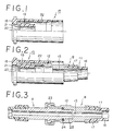
- a female connector member B is connected through the medium of a tube insertion terminal part 11 as illustrated in Fig. 2 to a dialytic liquid passing tube 16 having one end thereof connected to a dialytic liquid bag 10 as illustrated in Fig. 6, retained in place with an annular retaining member 17, and provided in the interior thereof with a flow path 13.
- An open end of an inserted part 12 of the female connector member B is closed with closing means which is formed in a cap proper.
- the closing means for example, is a tubularly projected part 19 which, as illustrated in Fig. 1 and Fig.
- the connector member B is inserted between an outer barrel 22 of the cylindrical body 15 and the tubularly projected part 19 formed inside the outer barrel 15.
- An open end of the connector member B is inserted tightly around the tubularly projected part 19.
- the connector part B is preferable to have the outer leading end part thereof formed in a converged shape.
- the cap is preferable from the standpoint of airtightness of contact with the connector member B and price to be made of thermoplastic resin such as polypropylene, polyethylene, vinyl chloride resin, or polystyrene, for example.
- the outer barrel 22 and the tubularly projected part 19 are preferable to be integrally formed.
- the air permeable filter member 21 is formed of filter paper or nonwoven fabric, for example, and is fastened by adhesion, fusion, or other means to the open part 20 formed in the bottom part.
- the dialytic solution bag (not shown) having the connector member B thereof covered with the cap of this invention as illustrated in Fig. 2 is stowed in a packing container (not shown), hermetically sealed therein, and then sterilized in an autoclave at temperature of 120°C, for example, for about 30 minutes.
- the steam in the autoclave permeates the wall of the packing container (bag of flexible vinyl chloride resin, for example) and enters the container interior and, at the same time, permeates through the wall of the flexible tube (tube of flexible vinyl chloride resin, for example) and enters the tube interior and also finds its way into the passage of the connector member, to effect sterilization of the entire container.
- the partial pressure of steam inside the tube is greatly lowered because the steam inside the tube is condensed. Since the air inside the packing container passes through the filter member add flows into the tube interior, however, the possibility of the tube being crushed or blocked is perfectly nil.
- the method of continuously applicable peritoneal dialysis (CAPD method) by the use of the dialytic solution bag is effected by opening the packing container, removing the cap, subjecting the connector member A connected to the catheter retained inside the peritoneum and the connector member B stripped of the cap to flame sterilization with alcohol lamp, then inserting an insertion terminal part 25 of a male connector member A into the female connector member B, locking the two connector members with a locking member 23, and sealing the locked joint watertightly with an O-ring 24.
- the connector members A and B are both preferable to be made of a heat-resistant corrosionproof material because they are subjected to the flame sterilization prior to use.
- the materials which fulfil the requirement include metals, ceramics, and heat-resistant resins, for example. Since these connector members are joined by shrink fit of one sort, it is desirable to have one of them made of a metallic material and the other member made of a ceramic material. It is particularly desirable to have the female connector member made of a metallic material and the male connector member made of a ceramic material.
- the metallic materials which are usable herein include stainless steel, titanium alloy, nickel, nickel alloy, and chromium-plated brass, for example.
- the ceramic materials which are usable herein include zirconia, silicon nitride, alumina, steatite, forsterite, silicon carbide, and silica, for example.
- An open end of a female connector member B made of nickel alloy, attached to the leading end of a tube of flexible vinyl chloride resin of a CAPD grade dialytic solution bag, and fixed in place with an annular retaining member 17 as illustrated in Fig. 1 and Fig. 2 was inserted around a tubularly projected part 19 of a cap provided with closing means projected from the bottom part of a cylindrical body of the cap coaxially relative to the cylindrical body and a filter member 21 disposed in an opening 20 formed in the bottom part.
- the dialytic liquid bag provided with the connector member B covered with the cap as described above was stowed and hermetically sealed in a bag obtained by superposing two sheets each of a three-layer construction of polypropylene-nylon-polypropylene and fusing the edges of the superposed sheets and subjected to autoclave sterilization at 120°C for about 30 minutes.
- autoclave sterilization at 120°C for about 30 minutes.
Landscapes
- Health & Medical Sciences (AREA)
- Heart & Thoracic Surgery (AREA)
- Pulmonology (AREA)
- Engineering & Computer Science (AREA)
- Anesthesiology (AREA)
- Biomedical Technology (AREA)
- Hematology (AREA)
- Life Sciences & Earth Sciences (AREA)
- Animal Behavior & Ethology (AREA)
- General Health & Medical Sciences (AREA)
- Public Health (AREA)
- Veterinary Medicine (AREA)
- External Artificial Organs (AREA)
Claims (5)
- Coiffe de protection pour un raccord d'outil médical qui comprend :- un corps cylindrique aveugle (15) présentant une douille extérieure (22),- un moyen (19) placé sur la partie de base du corps cylindrique (15) pour fermer une extrémité ouverte d'un élément de raccord (B) qui doit être protégé avec la coiffe, dans lequel le moyen de fermeture (19) est construit pour être une projection tubulaire de la partie de base du corps cylindrique (15) en direction de l'extrémité ouverte de celui-ci, de façon coaxiale par rapport au corps cylindrique, et pour être inséré dans l'extrémité ouverte de l'élément de raccord (B), sachant que l'extrémité ouverte de l'élément de raccord (B) est introduite entre la douille (22) et le corps tubulaire du moyen de fermeture (19) et étroitement emboîtée autour du moyen de fermeture (19) tubulaire qui dépasse,- un élément formant filtre (21), perméable à l'air, placé dans le moyen de fermeture (19) pour fermer une partie ouverte formée dans la partie de base de celui-ci,caractérisée en ce que :- le corps tubulaire de l'élément de fermeture (19) est cylindrique, et- la douille (22) de la coiffe est réalisée avec une taille telle par rapport au diamètre extérieur de l'extrémité ouverte de l'élément de raccord (B) qu'elle permet à la douille (22) de s'emboîter par rétrécissement autour de l'élément de raccord (B) sous l'effet thermique d'une stérilisation en autoclave.
- Coiffe de protection selon la revendication 1, dans laquelle la partie tubulaire qui dépasse (19) est formée en un seul bloc avec le corps cylindrique.
- Coiffe de protection selon la revendication 1 ou 2, dans laquelle la partie tubulaire qui dépasse (19) est faite d'une résine thermoplastique.
- Coiffe de protection selon l'une quelconque des revendications 1 à 3, dans laquelle la partie tubulaire qui dépasse (19) a sa partie d'extrémité avant extérieure qui a une forme convergente.
- Outil médical possédant un tube fermé en une extrémité et muni en son autre extrémité d'un élément de raccord (B) et ayant une extrémité ouverte de l'élément de raccord qui est couverte par une coiffe de protection destinée à un raccord d'outil médical tel que défini dans l'une des revendication 1 à 4.
Applications Claiming Priority (2)
| Application Number | Priority Date | Filing Date | Title |
|---|---|---|---|
| JP1145225A JPH07106220B2 (ja) | 1989-06-09 | 1989-06-09 | 医療用具コネクター用キャップ |
| JP145225/89 | 1989-06-09 |
Publications (2)
| Publication Number | Publication Date |
|---|---|
| EP0406584A1 EP0406584A1 (fr) | 1991-01-09 |
| EP0406584B1 true EP0406584B1 (fr) | 1994-09-07 |
Family
ID=15380239
Family Applications (1)
| Application Number | Title | Priority Date | Filing Date |
|---|---|---|---|
| EP19900110985 Expired - Lifetime EP0406584B1 (fr) | 1989-06-09 | 1990-06-11 | Capot de protection pour raccord médical |
Country Status (3)
| Country | Link |
|---|---|
| EP (1) | EP0406584B1 (fr) |
| JP (1) | JPH07106220B2 (fr) |
| DE (1) | DE69012236T2 (fr) |
Cited By (1)
| Publication number | Priority date | Publication date | Assignee | Title |
|---|---|---|---|---|
| WO2024145179A1 (fr) * | 2022-12-26 | 2024-07-04 | Baxter International Inc. | Capuchon ventilé de ligne d'alimentation en fluide médical, ensemble et procédé de stérilisation associé |
Families Citing this family (7)
| Publication number | Priority date | Publication date | Assignee | Title |
|---|---|---|---|---|
| DE4100837A1 (de) * | 1991-01-14 | 1992-07-16 | Volker Bertram | Adaptor mit trachealtubus |
| EP1305066B1 (fr) | 2000-07-22 | 2013-05-08 | E-WHA Fresenius Kabi Inc. | Dispositif d'alimentation liquide |
| WO2004014477A1 (fr) * | 2002-08-09 | 2004-02-19 | Yong-Nyun Kim | Coiffe de tube de distribution de liquide |
| US8523829B2 (en) * | 2004-01-29 | 2013-09-03 | Becton, Dickinson And Company | Intravenous delivery system |
| US20110276010A1 (en) * | 2010-05-06 | 2011-11-10 | Becton, Dickinson And Company | Systems and methods for providing a closed venting hazardous drug iv set |
| CN107206160B (zh) * | 2015-02-09 | 2022-03-25 | 株式会社小林 | 瓶针管套及使用该瓶针管套的输液组的前处置方法 |
| DE102022101151A1 (de) * | 2022-01-19 | 2023-07-20 | B. Braun Melsungen Aktiengesellschaft | Kappe für einen Konnektor eines enteralen Überleitungssets sowie Überleitungsset mit einer Kappe |
Family Cites Families (7)
| Publication number | Priority date | Publication date | Assignee | Title |
|---|---|---|---|---|
| DE2818146A1 (de) * | 1978-04-26 | 1979-11-08 | Fresenius Chem Pharm Ind | Verschlussteil fuer sterile medizinische apparate |
| JPS5599257A (en) * | 1979-01-23 | 1980-07-29 | Baxter Travenol Lab | Solution vessel for continuous hospital attending peritoneal dialysis |
| JPS62186871A (ja) * | 1986-02-12 | 1987-08-15 | テルモ株式会社 | 破断して分離可能な栓体を備えた管体 |
| JPS62186870A (ja) * | 1986-02-12 | 1987-08-15 | テルモ株式会社 | 分岐管 |
| JPS62201160A (ja) * | 1986-02-27 | 1987-09-04 | 日本ゼオン株式会社 | 注入管 |
| DE8625003U1 (de) * | 1986-09-18 | 1986-11-06 | B. Braun Melsungen Ag, 3508 Melsungen | Entlüftungsventil |
| DE8906628U1 (de) * | 1988-06-01 | 1989-07-27 | Sterimed Gesellschaft für medizinischen Bedarf mbH, 6600 Saarbrücken | Luer-Lock-Überwurfmutter für Katheteransatzstücke |
-
1989
- 1989-06-09 JP JP1145225A patent/JPH07106220B2/ja not_active Expired - Fee Related
-
1990
- 1990-06-11 EP EP19900110985 patent/EP0406584B1/fr not_active Expired - Lifetime
- 1990-06-11 DE DE1990612236 patent/DE69012236T2/de not_active Expired - Fee Related
Cited By (1)
| Publication number | Priority date | Publication date | Assignee | Title |
|---|---|---|---|---|
| WO2024145179A1 (fr) * | 2022-12-26 | 2024-07-04 | Baxter International Inc. | Capuchon ventilé de ligne d'alimentation en fluide médical, ensemble et procédé de stérilisation associé |
Also Published As
| Publication number | Publication date |
|---|---|
| EP0406584A1 (fr) | 1991-01-09 |
| DE69012236D1 (de) | 1994-10-13 |
| DE69012236T2 (de) | 1994-12-22 |
| JPH0312171A (ja) | 1991-01-21 |
| JPH07106220B2 (ja) | 1995-11-15 |
Similar Documents
| Publication | Publication Date | Title |
|---|---|---|
| US5290253A (en) | Cap for medical tool connection and medical tool | |
| US4346703A (en) | Solution container for continuous ambulatory peritoneal dialysis | |
| EP0093837B1 (fr) | Dispositif de connexion pour raccorder deux tuyaux flexibles ou analogues | |
| US4439188A (en) | Tube connector | |
| EP0175428B1 (fr) | Raccord pour tube, spécialement prévu pour irradiation antimicrobienne | |
| US4668217A (en) | Connector for therapeutic tubing and medical solution bag device using the connector | |
| US4209013A (en) | Sterile connection system using flexible container | |
| US4636313A (en) | Flexible filter disposed within flexible conductor | |
| EP1297861B1 (fr) | Ensembles de connecteur, systèmes de fluide | |
| US5057074A (en) | Medical container replacing method | |
| US4508367A (en) | Connector | |
| US5330464A (en) | Reliable breakable closure mechanism | |
| US4588402A (en) | Connector for medical tubing and medical solution bag device using the connector | |
| CA1155725A (fr) | Recipient pour solution permettant la dialyse peritoneale ambulatoire continue | |
| KR100400144B1 (ko) | 로킹덮개를갖는반송세트커넥터및그사용방법 | |
| JPH09509866A (ja) | 真空による創傷の縫合及び/又は吸引による分泌物等の吸い出しのための装置 | |
| JPH02503272A (ja) | 薬剤のような材料を液体に接触させる装置 | |
| US4722727A (en) | Flexible container | |
| EP0406584A1 (fr) | Capot de protection pour raccord médical | |
| JPH07478A (ja) | 溶液供給方法及び溶液バッグ | |
| EP0398321B1 (fr) | Membrane de fermeture munie d'une membrane d'étanchéité | |
| US4215690A (en) | Medical needle | |
| US4163722A (en) | Universal dialyzer end cap | |
| JPS59139270A (ja) | 医療用コネクタ− | |
| EP3216485B1 (fr) | Ferrure pour un dispositif médical approprié pour une perfusion entérale ou parentale et une transfusion |
Legal Events
| Date | Code | Title | Description |
|---|---|---|---|
| PUAI | Public reference made under article 153(3) epc to a published international application that has entered the european phase |
Free format text: ORIGINAL CODE: 0009012 |
|
| 17P | Request for examination filed |
Effective date: 19900611 |
|
| AK | Designated contracting states |
Kind code of ref document: A1 Designated state(s): BE DE FR GB IT SE |
|
| 17Q | First examination report despatched |
Effective date: 19920824 |
|
| GRAA | (expected) grant |
Free format text: ORIGINAL CODE: 0009210 |
|
| AK | Designated contracting states |
Kind code of ref document: B1 Designated state(s): BE DE FR GB IT SE |
|
| ET | Fr: translation filed | ||
| REF | Corresponds to: |
Ref document number: 69012236 Country of ref document: DE Date of ref document: 19941013 |
|
| ITF | It: translation for a ep patent filed | ||
| EAL | Se: european patent in force in sweden |
Ref document number: 90110985.0 |
|
| PLBE | No opposition filed within time limit |
Free format text: ORIGINAL CODE: 0009261 |
|
| STAA | Information on the status of an ep patent application or granted ep patent |
Free format text: STATUS: NO OPPOSITION FILED WITHIN TIME LIMIT |
|
| 26N | No opposition filed | ||
| PGFP | Annual fee paid to national office [announced via postgrant information from national office to epo] |
Ref country code: GB Payment date: 19970602 Year of fee payment: 8 |
|
| PGFP | Annual fee paid to national office [announced via postgrant information from national office to epo] |
Ref country code: FR Payment date: 19970610 Year of fee payment: 8 |
|
| PGFP | Annual fee paid to national office [announced via postgrant information from national office to epo] |
Ref country code: SE Payment date: 19970618 Year of fee payment: 8 |
|
| PGFP | Annual fee paid to national office [announced via postgrant information from national office to epo] |
Ref country code: DE Payment date: 19970620 Year of fee payment: 8 |
|
| PGFP | Annual fee paid to national office [announced via postgrant information from national office to epo] |
Ref country code: BE Payment date: 19970805 Year of fee payment: 8 |
|
| PG25 | Lapsed in a contracting state [announced via postgrant information from national office to epo] |
Ref country code: GB Free format text: LAPSE BECAUSE OF NON-PAYMENT OF DUE FEES Effective date: 19980611 |
|
| PG25 | Lapsed in a contracting state [announced via postgrant information from national office to epo] |
Ref country code: SE Free format text: LAPSE BECAUSE OF NON-PAYMENT OF DUE FEES Effective date: 19980612 |
|
| PG25 | Lapsed in a contracting state [announced via postgrant information from national office to epo] |
Ref country code: BE Free format text: LAPSE BECAUSE OF NON-PAYMENT OF DUE FEES Effective date: 19980630 |
|
| BERE | Be: lapsed |
Owner name: TERUMO K.K. Effective date: 19980630 |
|
| GBPC | Gb: european patent ceased through non-payment of renewal fee |
Effective date: 19980611 |
|
| PG25 | Lapsed in a contracting state [announced via postgrant information from national office to epo] |
Ref country code: FR Free format text: LAPSE BECAUSE OF NON-PAYMENT OF DUE FEES Effective date: 19990226 |
|
| EUG | Se: european patent has lapsed |
Ref document number: 90110985.0 |
|
| PG25 | Lapsed in a contracting state [announced via postgrant information from national office to epo] |
Ref country code: DE Free format text: LAPSE BECAUSE OF NON-PAYMENT OF DUE FEES Effective date: 19990401 |
|
| REG | Reference to a national code |
Ref country code: FR Ref legal event code: ST |
|
| PG25 | Lapsed in a contracting state [announced via postgrant information from national office to epo] |
Ref country code: IT Free format text: LAPSE BECAUSE OF NON-PAYMENT OF DUE FEES Effective date: 20050611 |