EP0420276A2 - Dispositif d'affichage et procédÀ© de fabrication - Google Patents
Dispositif d'affichage et procédÀ© de fabrication Download PDFInfo
- Publication number
- EP0420276A2 EP0420276A2 EP90118697A EP90118697A EP0420276A2 EP 0420276 A2 EP0420276 A2 EP 0420276A2 EP 90118697 A EP90118697 A EP 90118697A EP 90118697 A EP90118697 A EP 90118697A EP 0420276 A2 EP0420276 A2 EP 0420276A2
- Authority
- EP
- European Patent Office
- Prior art keywords
- image
- photo
- layer
- polymerizable
- color
- Prior art date
- Legal status (The legal status is an assumption and is not a legal conclusion. Google has not performed a legal analysis and makes no representation as to the accuracy of the status listed.)
- Withdrawn
Links
- 238000000034 method Methods 0.000 title claims abstract description 38
- 238000004519 manufacturing process Methods 0.000 title description 7
- 239000010410 layer Substances 0.000 claims abstract description 124
- 239000000463 material Substances 0.000 claims abstract description 61
- 239000012790 adhesive layer Substances 0.000 claims abstract description 37
- 238000006116 polymerization reaction Methods 0.000 claims abstract description 6
- 239000000853 adhesive Substances 0.000 claims description 23
- 230000001070 adhesive effect Effects 0.000 claims description 23
- 239000000203 mixture Substances 0.000 claims description 19
- 239000007788 liquid Substances 0.000 claims description 16
- 239000003505 polymerization initiator Substances 0.000 claims description 12
- 150000001875 compounds Chemical class 0.000 claims description 11
- 238000010438 heat treatment Methods 0.000 claims description 7
- 229920000620 organic polymer Polymers 0.000 claims description 6
- 239000000049 pigment Substances 0.000 claims description 6
- 229920000642 polymer Polymers 0.000 claims description 6
- 229920000915 polyvinyl chloride Polymers 0.000 claims description 6
- 239000004800 polyvinyl chloride Substances 0.000 claims description 6
- 229920003023 plastic Polymers 0.000 claims description 5
- 239000002491 polymer binding agent Substances 0.000 claims description 5
- 238000000926 separation method Methods 0.000 claims description 5
- 230000003213 activating effect Effects 0.000 claims description 4
- 239000004033 plastic Substances 0.000 claims description 4
- 229920000515 polycarbonate Polymers 0.000 claims description 4
- 239000004417 polycarbonate Substances 0.000 claims description 4
- 229920001169 thermoplastic Polymers 0.000 claims description 4
- 239000004416 thermosoftening plastic Substances 0.000 claims description 4
- 229920000178 Acrylic resin Polymers 0.000 claims description 3
- 239000004925 Acrylic resin Substances 0.000 claims description 3
- 239000003999 initiator Substances 0.000 claims description 3
- 238000010030 laminating Methods 0.000 claims description 2
- 230000001678 irradiating effect Effects 0.000 claims 1
- ZWEHNKRNPOVVGH-UHFFFAOYSA-N 2-Butanone Chemical compound CCC(C)=O ZWEHNKRNPOVVGH-UHFFFAOYSA-N 0.000 description 12
- 239000011248 coating agent Substances 0.000 description 11
- 238000000576 coating method Methods 0.000 description 11
- OKKJLVBELUTLKV-UHFFFAOYSA-N Methanol Chemical compound OC OKKJLVBELUTLKV-UHFFFAOYSA-N 0.000 description 9
- VVBLNCFGVYUYGU-UHFFFAOYSA-N 4,4'-Bis(dimethylamino)benzophenone Chemical compound C1=CC(N(C)C)=CC=C1C(=O)C1=CC=C(N(C)C)C=C1 VVBLNCFGVYUYGU-UHFFFAOYSA-N 0.000 description 8
- 229920005668 polycarbonate resin Polymers 0.000 description 8
- 239000004431 polycarbonate resin Substances 0.000 description 8
- 239000011347 resin Substances 0.000 description 8
- 229920005989 resin Polymers 0.000 description 8
- 238000003475 lamination Methods 0.000 description 7
- -1 benzoin ethers Chemical class 0.000 description 6
- 230000003287 optical effect Effects 0.000 description 6
- 239000000126 substance Substances 0.000 description 6
- 238000007650 screen-printing Methods 0.000 description 5
- 230000007547 defect Effects 0.000 description 4
- 239000005020 polyethylene terephthalate Substances 0.000 description 4
- 229920000139 polyethylene terephthalate Polymers 0.000 description 4
- LYCAIKOWRPUZTN-UHFFFAOYSA-N Ethylene glycol Chemical compound OCCO LYCAIKOWRPUZTN-UHFFFAOYSA-N 0.000 description 3
- DNIAPMSPPWPWGF-UHFFFAOYSA-N Propylene glycol Chemical compound CC(O)CO DNIAPMSPPWPWGF-UHFFFAOYSA-N 0.000 description 3
- 244000028419 Styrax benzoin Species 0.000 description 3
- 235000000126 Styrax benzoin Nutrition 0.000 description 3
- 235000008411 Sumatra benzointree Nutrition 0.000 description 3
- ISAOCJYIOMOJEB-UHFFFAOYSA-N benzoin Chemical compound C=1C=CC=CC=1C(O)C(=O)C1=CC=CC=C1 ISAOCJYIOMOJEB-UHFFFAOYSA-N 0.000 description 3
- RWCCWEUUXYIKHB-UHFFFAOYSA-N benzophenone Chemical compound C=1C=CC=CC=1C(=O)C1=CC=CC=C1 RWCCWEUUXYIKHB-UHFFFAOYSA-N 0.000 description 3
- 239000012965 benzophenone Substances 0.000 description 3
- 229920001577 copolymer Polymers 0.000 description 3
- 235000019382 gum benzoic Nutrition 0.000 description 3
- 239000003112 inhibitor Substances 0.000 description 3
- NWVVVBRKAWDGAB-UHFFFAOYSA-N p-methoxyphenol Chemical compound COC1=CC=C(O)C=C1 NWVVVBRKAWDGAB-UHFFFAOYSA-N 0.000 description 3
- 239000000243 solution Substances 0.000 description 3
- 229920002554 vinyl polymer Polymers 0.000 description 3
- NSWNXQGJAPQOID-UHFFFAOYSA-N 2-(2-chlorophenyl)-4,5-diphenyl-1h-imidazole Chemical class ClC1=CC=CC=C1C1=NC(C=2C=CC=CC=2)=C(C=2C=CC=CC=2)N1 NSWNXQGJAPQOID-UHFFFAOYSA-N 0.000 description 2
- HCLJOFJIQIJXHS-UHFFFAOYSA-N 2-[2-[2-(2-prop-2-enoyloxyethoxy)ethoxy]ethoxy]ethyl prop-2-enoate Chemical compound C=CC(=O)OCCOCCOCCOCCOC(=O)C=C HCLJOFJIQIJXHS-UHFFFAOYSA-N 0.000 description 2
- XLLIQLLCWZCATF-UHFFFAOYSA-N 2-methoxyethyl acetate Chemical compound COCCOC(C)=O XLLIQLLCWZCATF-UHFFFAOYSA-N 0.000 description 2
- BMTAFVWTTFSTOG-UHFFFAOYSA-N Butylate Chemical compound CCSC(=O)N(CC(C)C)CC(C)C BMTAFVWTTFSTOG-UHFFFAOYSA-N 0.000 description 2
- QIGBRXMKCJKVMJ-UHFFFAOYSA-N Hydroquinone Chemical compound OC1=CC=C(O)C=C1 QIGBRXMKCJKVMJ-UHFFFAOYSA-N 0.000 description 2
- CERQOIWHTDAKMF-UHFFFAOYSA-N Methacrylic acid Chemical compound CC(=C)C(O)=O CERQOIWHTDAKMF-UHFFFAOYSA-N 0.000 description 2
- 239000004952 Polyamide Substances 0.000 description 2
- CDBYLPFSWZWCQE-UHFFFAOYSA-L Sodium Carbonate Chemical compound [Na+].[Na+].[O-]C([O-])=O CDBYLPFSWZWCQE-UHFFFAOYSA-L 0.000 description 2
- PPBRXRYQALVLMV-UHFFFAOYSA-N Styrene Chemical compound C=CC1=CC=CC=C1 PPBRXRYQALVLMV-UHFFFAOYSA-N 0.000 description 2
- DAKWPKUUDNSNPN-UHFFFAOYSA-N Trimethylolpropane triacrylate Chemical compound C=CC(=O)OCC(CC)(COC(=O)C=C)COC(=O)C=C DAKWPKUUDNSNPN-UHFFFAOYSA-N 0.000 description 2
- 229960002130 benzoin Drugs 0.000 description 2
- 229920002301 cellulose acetate Polymers 0.000 description 2
- 239000003086 colorant Substances 0.000 description 2
- 230000000052 comparative effect Effects 0.000 description 2
- 238000005520 cutting process Methods 0.000 description 2
- 229920003229 poly(methyl methacrylate) Polymers 0.000 description 2
- 229920002647 polyamide Polymers 0.000 description 2
- 229920000728 polyester Polymers 0.000 description 2
- 239000004926 polymethyl methacrylate Substances 0.000 description 2
- 229920002689 polyvinyl acetate Polymers 0.000 description 2
- 239000011118 polyvinyl acetate Substances 0.000 description 2
- 238000007639 printing Methods 0.000 description 2
- WQGWDDDVZFFDIG-UHFFFAOYSA-N pyrogallol Chemical compound OC1=CC=CC(O)=C1O WQGWDDDVZFFDIG-UHFFFAOYSA-N 0.000 description 2
- 238000003860 storage Methods 0.000 description 2
- XLYOFNOQVPJJNP-UHFFFAOYSA-N water Substances O XLYOFNOQVPJJNP-UHFFFAOYSA-N 0.000 description 2
- MYWOJODOMFBVCB-UHFFFAOYSA-N 1,2,6-trimethylphenanthrene Chemical compound CC1=CC=C2C3=CC(C)=CC=C3C=CC2=C1C MYWOJODOMFBVCB-UHFFFAOYSA-N 0.000 description 1
- LMGYOBQJBQAZKC-UHFFFAOYSA-N 1-(2-ethylphenyl)-2-hydroxy-2-phenylethanone Chemical compound CCC1=CC=CC=C1C(=O)C(O)C1=CC=CC=C1 LMGYOBQJBQAZKC-UHFFFAOYSA-N 0.000 description 1
- WJFKNYWRSNBZNX-UHFFFAOYSA-N 10H-phenothiazine Chemical compound C1=CC=C2NC3=CC=CC=C3SC2=C1 WJFKNYWRSNBZNX-UHFFFAOYSA-N 0.000 description 1
- KWVGIHKZDCUPEU-UHFFFAOYSA-N 2,2-dimethoxy-2-phenylacetophenone Chemical compound C=1C=CC=CC=1C(OC)(OC)C(=O)C1=CC=CC=C1 KWVGIHKZDCUPEU-UHFFFAOYSA-N 0.000 description 1
- SMZOUWXMTYCWNB-UHFFFAOYSA-N 2-(2-methoxy-5-methylphenyl)ethanamine Chemical compound COC1=CC=C(C)C=C1CCN SMZOUWXMTYCWNB-UHFFFAOYSA-N 0.000 description 1
- XIOGJAPOAUEYJO-UHFFFAOYSA-N 2-(2-methoxyphenyl)-4,5-diphenyl-1h-imidazole Chemical class COC1=CC=CC=C1C1=NC(C=2C=CC=CC=2)=C(C=2C=CC=CC=2)N1 XIOGJAPOAUEYJO-UHFFFAOYSA-N 0.000 description 1
- XNWFRZJHXBZDAG-UHFFFAOYSA-N 2-METHOXYETHANOL Chemical compound COCCO XNWFRZJHXBZDAG-UHFFFAOYSA-N 0.000 description 1
- TXBCBTDQIULDIA-UHFFFAOYSA-N 2-[[3-hydroxy-2,2-bis(hydroxymethyl)propoxy]methyl]-2-(hydroxymethyl)propane-1,3-diol Chemical compound OCC(CO)(CO)COCC(CO)(CO)CO TXBCBTDQIULDIA-UHFFFAOYSA-N 0.000 description 1
- POAOYUHQDCAZBD-UHFFFAOYSA-N 2-butoxyethanol Chemical compound CCCCOCCO POAOYUHQDCAZBD-UHFFFAOYSA-N 0.000 description 1
- KMNCBSZOIQAUFX-UHFFFAOYSA-N 2-ethoxy-1,2-diphenylethanone Chemical compound C=1C=CC=CC=1C(OCC)C(=O)C1=CC=CC=C1 KMNCBSZOIQAUFX-UHFFFAOYSA-N 0.000 description 1
- SJEBAWHUJDUKQK-UHFFFAOYSA-N 2-ethylanthraquinone Chemical compound C1=CC=C2C(=O)C3=CC(CC)=CC=C3C(=O)C2=C1 SJEBAWHUJDUKQK-UHFFFAOYSA-N 0.000 description 1
- VZMLJEYQUZKERO-UHFFFAOYSA-N 2-hydroxy-1-(2-methylphenyl)-2-phenylethanone Chemical compound CC1=CC=CC=C1C(=O)C(O)C1=CC=CC=C1 VZMLJEYQUZKERO-UHFFFAOYSA-N 0.000 description 1
- BQZJOQXSCSZQPS-UHFFFAOYSA-N 2-methoxy-1,2-diphenylethanone Chemical compound C=1C=CC=CC=1C(OC)C(=O)C1=CC=CC=C1 BQZJOQXSCSZQPS-UHFFFAOYSA-N 0.000 description 1
- XLLXMBCBJGATSP-UHFFFAOYSA-N 2-phenylethenol Chemical compound OC=CC1=CC=CC=C1 XLLXMBCBJGATSP-UHFFFAOYSA-N 0.000 description 1
- PYSRRFNXTXNWCD-UHFFFAOYSA-N 3-(2-phenylethenyl)furan-2,5-dione Chemical compound O=C1OC(=O)C(C=CC=2C=CC=CC=2)=C1 PYSRRFNXTXNWCD-UHFFFAOYSA-N 0.000 description 1
- JIGUICYYOYEXFS-UHFFFAOYSA-N 3-tert-butylbenzene-1,2-diol Chemical compound CC(C)(C)C1=CC=CC(O)=C1O JIGUICYYOYEXFS-UHFFFAOYSA-N 0.000 description 1
- YYVYAPXYZVYDHN-UHFFFAOYSA-N 9,10-phenanthroquinone Chemical compound C1=CC=C2C(=O)C(=O)C3=CC=CC=C3C2=C1 YYVYAPXYZVYDHN-UHFFFAOYSA-N 0.000 description 1
- NIXOWILDQLNWCW-UHFFFAOYSA-M Acrylate Chemical compound [O-]C(=O)C=C NIXOWILDQLNWCW-UHFFFAOYSA-M 0.000 description 1
- 229920001747 Cellulose diacetate Polymers 0.000 description 1
- 229920002284 Cellulose triacetate Polymers 0.000 description 1
- VVQNEPGJFQJSBK-UHFFFAOYSA-N Methyl methacrylate Chemical compound COC(=O)C(C)=C VVQNEPGJFQJSBK-UHFFFAOYSA-N 0.000 description 1
- 239000000020 Nitrocellulose Substances 0.000 description 1
- 239000004677 Nylon Substances 0.000 description 1
- CBENFWSGALASAD-UHFFFAOYSA-N Ozone Chemical compound [O-][O+]=O CBENFWSGALASAD-UHFFFAOYSA-N 0.000 description 1
- ALQSHHUCVQOPAS-UHFFFAOYSA-N Pentane-1,5-diol Chemical compound OCCCCCO ALQSHHUCVQOPAS-UHFFFAOYSA-N 0.000 description 1
- 229920002845 Poly(methacrylic acid) Polymers 0.000 description 1
- 229920002319 Poly(methyl acrylate) Polymers 0.000 description 1
- 239000004698 Polyethylene Substances 0.000 description 1
- 239000002202 Polyethylene glycol Substances 0.000 description 1
- 239000004793 Polystyrene Substances 0.000 description 1
- 239000004372 Polyvinyl alcohol Substances 0.000 description 1
- 229920002125 Sokalan® Polymers 0.000 description 1
- 229920000147 Styrene maleic anhydride Polymers 0.000 description 1
- ZJCCRDAZUWHFQH-UHFFFAOYSA-N Trimethylolpropane Chemical compound CCC(CO)(CO)CO ZJCCRDAZUWHFQH-UHFFFAOYSA-N 0.000 description 1
- 229920002433 Vinyl chloride-vinyl acetate copolymer Polymers 0.000 description 1
- NNLVGZFZQQXQNW-ADJNRHBOSA-N [(2r,3r,4s,5r,6s)-4,5-diacetyloxy-3-[(2s,3r,4s,5r,6r)-3,4,5-triacetyloxy-6-(acetyloxymethyl)oxan-2-yl]oxy-6-[(2r,3r,4s,5r,6s)-4,5,6-triacetyloxy-2-(acetyloxymethyl)oxan-3-yl]oxyoxan-2-yl]methyl acetate Chemical compound O([C@@H]1O[C@@H]([C@H]([C@H](OC(C)=O)[C@H]1OC(C)=O)O[C@H]1[C@@H]([C@@H](OC(C)=O)[C@H](OC(C)=O)[C@@H](COC(C)=O)O1)OC(C)=O)COC(=O)C)[C@@H]1[C@@H](COC(C)=O)O[C@@H](OC(C)=O)[C@H](OC(C)=O)[C@H]1OC(C)=O NNLVGZFZQQXQNW-ADJNRHBOSA-N 0.000 description 1
- FJWGYAHXMCUOOM-QHOUIDNNSA-N [(2s,3r,4s,5r,6r)-2-[(2r,3r,4s,5r,6s)-4,5-dinitrooxy-2-(nitrooxymethyl)-6-[(2r,3r,4s,5r,6s)-4,5,6-trinitrooxy-2-(nitrooxymethyl)oxan-3-yl]oxyoxan-3-yl]oxy-3,5-dinitrooxy-6-(nitrooxymethyl)oxan-4-yl] nitrate Chemical compound O([C@@H]1O[C@@H]([C@H]([C@H](O[N+]([O-])=O)[C@H]1O[N+]([O-])=O)O[C@H]1[C@@H]([C@@H](O[N+]([O-])=O)[C@H](O[N+]([O-])=O)[C@@H](CO[N+]([O-])=O)O1)O[N+]([O-])=O)CO[N+](=O)[O-])[C@@H]1[C@@H](CO[N+]([O-])=O)O[C@@H](O[N+]([O-])=O)[C@H](O[N+]([O-])=O)[C@H]1O[N+]([O-])=O FJWGYAHXMCUOOM-QHOUIDNNSA-N 0.000 description 1
- ARNIZPSLPHFDED-UHFFFAOYSA-N [4-(dimethylamino)phenyl]-(4-methoxyphenyl)methanone Chemical compound C1=CC(OC)=CC=C1C(=O)C1=CC=C(N(C)C)C=C1 ARNIZPSLPHFDED-UHFFFAOYSA-N 0.000 description 1
- DHKHKXVYLBGOIT-UHFFFAOYSA-N acetaldehyde Diethyl Acetal Natural products CCOC(C)OCC DHKHKXVYLBGOIT-UHFFFAOYSA-N 0.000 description 1
- 150000001241 acetals Chemical class 0.000 description 1
- 239000002390 adhesive tape Substances 0.000 description 1
- 239000012670 alkaline solution Substances 0.000 description 1
- 150000008365 aromatic ketones Chemical class 0.000 description 1
- QVQLCTNNEUAWMS-UHFFFAOYSA-N barium oxide Chemical compound [Ba]=O QVQLCTNNEUAWMS-UHFFFAOYSA-N 0.000 description 1
- 229910001864 baryta Inorganic materials 0.000 description 1
- AOJOEFVRHOZDFN-UHFFFAOYSA-N benzyl 2-methylprop-2-enoate Chemical compound CC(=C)C(=O)OCC1=CC=CC=C1 AOJOEFVRHOZDFN-UHFFFAOYSA-N 0.000 description 1
- 239000011230 binding agent Substances 0.000 description 1
- 230000015572 biosynthetic process Effects 0.000 description 1
- VYHBFRJRBHMIQZ-UHFFFAOYSA-N bis[4-(diethylamino)phenyl]methanone Chemical compound C1=CC(N(CC)CC)=CC=C1C(=O)C1=CC=C(N(CC)CC)C=C1 VYHBFRJRBHMIQZ-UHFFFAOYSA-N 0.000 description 1
- IAQRGUVFOMOMEM-UHFFFAOYSA-N butene Natural products CC=CC IAQRGUVFOMOMEM-UHFFFAOYSA-N 0.000 description 1
- 239000006229 carbon black Substances 0.000 description 1
- 239000000539 dimer Substances 0.000 description 1
- 238000005553 drilling Methods 0.000 description 1
- FPVGTPBMTFTMRT-NSKUCRDLSA-L fast yellow Chemical compound [Na+].[Na+].C1=C(S([O-])(=O)=O)C(N)=CC=C1\N=N\C1=CC=C(S([O-])(=O)=O)C=C1 FPVGTPBMTFTMRT-NSKUCRDLSA-L 0.000 description 1
- 235000019233 fast yellow AB Nutrition 0.000 description 1
- XXMIOPMDWAUFGU-UHFFFAOYSA-N hexane-1,6-diol Chemical compound OCCCCCCO XXMIOPMDWAUFGU-UHFFFAOYSA-N 0.000 description 1
- 239000000976 ink Substances 0.000 description 1
- 230000031700 light absorption Effects 0.000 description 1
- QSHDDOUJBYECFT-UHFFFAOYSA-N mercury Chemical compound [Hg] QSHDDOUJBYECFT-UHFFFAOYSA-N 0.000 description 1
- 229910052753 mercury Inorganic materials 0.000 description 1
- 229920003145 methacrylic acid copolymer Polymers 0.000 description 1
- 229940117841 methacrylic acid copolymer Drugs 0.000 description 1
- 125000004184 methoxymethyl group Chemical group [H]C([H])([H])OC([H])([H])* 0.000 description 1
- YDKNBNOOCSNPNS-UHFFFAOYSA-N methyl 1,3-benzoxazole-2-carboxylate Chemical compound C1=CC=C2OC(C(=O)OC)=NC2=C1 YDKNBNOOCSNPNS-UHFFFAOYSA-N 0.000 description 1
- 229940086559 methyl benzoin Drugs 0.000 description 1
- JESXATFQYMPTNL-UHFFFAOYSA-N mono-hydroxyphenyl-ethylene Natural products OC1=CC=CC=C1C=C JESXATFQYMPTNL-UHFFFAOYSA-N 0.000 description 1
- SLCVBVWXLSEKPL-UHFFFAOYSA-N neopentyl glycol Chemical compound OCC(C)(C)CO SLCVBVWXLSEKPL-UHFFFAOYSA-N 0.000 description 1
- 229920001220 nitrocellulos Polymers 0.000 description 1
- 229920001778 nylon Polymers 0.000 description 1
- WXZMFSXDPGVJKK-UHFFFAOYSA-N pentaerythritol Chemical compound OCC(CO)(CO)CO WXZMFSXDPGVJKK-UHFFFAOYSA-N 0.000 description 1
- 229950000688 phenothiazine Drugs 0.000 description 1
- 239000002985 plastic film Substances 0.000 description 1
- 229920006255 plastic film Polymers 0.000 description 1
- 229920001485 poly(butyl acrylate) polymer Polymers 0.000 description 1
- 229920001490 poly(butyl methacrylate) polymer Polymers 0.000 description 1
- 229920000058 polyacrylate Polymers 0.000 description 1
- 239000004584 polyacrylic acid Substances 0.000 description 1
- 229920000120 polyethyl acrylate Polymers 0.000 description 1
- 229920000573 polyethylene Polymers 0.000 description 1
- 229920001223 polyethylene glycol Polymers 0.000 description 1
- 229920006324 polyoxymethylene Polymers 0.000 description 1
- 229920001451 polypropylene glycol Polymers 0.000 description 1
- 229920002223 polystyrene Polymers 0.000 description 1
- 229920002451 polyvinyl alcohol Polymers 0.000 description 1
- 229920001289 polyvinyl ether Polymers 0.000 description 1
- 229940079877 pyrogallol Drugs 0.000 description 1
- 229910000029 sodium carbonate Inorganic materials 0.000 description 1
- 235000017550 sodium carbonate Nutrition 0.000 description 1
- 150000005846 sugar alcohols Polymers 0.000 description 1
- 229920001187 thermosetting polymer Polymers 0.000 description 1
- 125000000391 vinyl group Chemical group [H]C([*])=C([H])[H] 0.000 description 1
- 230000004304 visual acuity Effects 0.000 description 1
Images
Classifications
-
- G—PHYSICS
- G03—PHOTOGRAPHY; CINEMATOGRAPHY; ANALOGOUS TECHNIQUES USING WAVES OTHER THAN OPTICAL WAVES; ELECTROGRAPHY; HOLOGRAPHY
- G03F—PHOTOMECHANICAL PRODUCTION OF TEXTURED OR PATTERNED SURFACES, e.g. FOR PRINTING, FOR PROCESSING OF SEMICONDUCTOR DEVICES; MATERIALS THEREFOR; ORIGINALS THEREFOR; APPARATUS SPECIALLY ADAPTED THEREFOR
- G03F7/00—Photomechanical, e.g. photolithographic, production of textured or patterned surfaces, e.g. printing surfaces; Materials therefor, e.g. comprising photoresists; Apparatus specially adapted therefor
- G03F7/0005—Production of optical devices or components in so far as characterised by the lithographic processes or materials used therefor
- G03F7/0007—Filters, e.g. additive colour filters; Components for display devices
Definitions
- the present invention relates to displays such as meter panels of automobiles and advertising displays and a process for production thereof.
- Meter panels are usually produced by repeated screen printing method using plastic plates such as polycarbonate resin, acrylic resin and polyvinyl chloride resin plates.
- plastic plates such as polycarbonate resin, acrylic resin and polyvinyl chloride resin plates.
- the screen printing must be repeated many times which are the same as the variety of the colors for forming multi-color images. Accordingly, a great deal of labor and time are necessitated for the toning by mixing inks and tuning up of the screen printing machine.
- J. P. KOKOKU Japanese Patent Publication for Opposition Purpose
- 'J. P. KOKAI' Japanese Patent Unexamined Published Application
- J. P. KOKAI No. 59-97140 discloses a process for overcoming the above-described defects wherein the image of each color is transferred onto an image-receiving sheet having a photo-polymerizable image-receiving layer prior to the transfer of the image of each color onto the permanent support, then the image is transferred onto the permanent support and the photo-polymerizable receiving layer is fixed by the whole image exposure.
- this process is effective for the production of color-proofing printing sheets, it has defects when it is employed for the production of meter panels. Namely, the defects are that the reliability thereof is unsatisfactory, since the adhesion to the permanent support is insufficient and the layer is peeled off from the support or it expands during the production steps or storage at a high temperature and at a high humidity.
- meter dial plates of automobils can be used not only under the severe condition, for example, requiring heat-resistance, light-resistance, and temperature change-resistance, but also have to retain the physical resistance for cutting the plate so as to incorporate it into meter case, drilling apertures for providing with indicators or fixing with bolts.
- many meter dial plates are prepared by the conventional screen-printing method, so that the thus prepared multicolor printed surface thereof is not sufficient for high-grade and colored meter dial plates. Therefore, it has been required to develop the technique for preparing the full colored plates having high image strenght, high density and high resolving power.
- a primary object of the present invention is to provide a display in which the adhesion between the photo-polymerizable image-receiving layer having a color image formed thereon and the light-transmitting permanent support is improved.
- Another object of the present invention is to provide a process for preparing a display in which the adhesion between the photo-polymerizable image-receiving layer having a color image formed thereon and the light-transmitting permanent support is improved by the transfer of a color image.
- the object of the present invention is attained by a display comprising a color image forming layer provided on a light transmitting permanent suppot via a photo-polymerizable adhesive layer, and a photo-polymerizable image-receiving layer closely adhered to the color image forming layer.
- Another aspect of the present invention is also attained by a process for producing the display comprising the steps of forming a color image on a photo-polymerizable image-receiving layer of a photosensitive image-receiving material, placing the material upon a photo-polymerizable adhesive layer formed on a light-transmitting permanent support to form a laminate so that the photo-polymerizable image-receiving layer and the photo-polymerizable adhesive layer face each other and then exposing the laminate to light so as to closely adhere the photo-polymerizable image-receiving layer and the photo-polymerizable adhesive layer to their adjacent layers, respectively, by the photo-polymerization.
- the photo-polymerizable adhesive layer of the present invention may be made of either a liquid photo-polymerizable adhesive or dry film-type photo-polymerizable adhesive. From the viewpoint of simplification of the process, the dry film-type photo-polymerizable adhesive is preferred.
- the photo-polymerizable composition layer made of the dry film-type photo-polymerizable adhesive comprises:
- the non-gaseous ethylenically unsaturated compounds usable in the present invention include compounds described in J.P. KOKOKU Nos. 35-5093, 35-14719 and 44-28727 and J.P. KOKAI No. 59-113423.
- Preferred examples of them include acrylic or methacrylic acid polyesters of polyhydric alcohols such as ethylene glycol, propylene glycol, polyethylene glycol, polypropylene glycol, 1,5-pentanediol, neopentyl glycol, 1,6-hexanediol, trimethylolpropane, pentaerythritol and dipentaerythritol.
- thermoplastic organic polymer binders are particularly preferably vinyl or acrylic polymers from the viewpoint of the compatibility with the above-described ethylenically unsaturated compound and photo-polymerization initiator.
- these polymers include polyvinyl chloride, polyacrylic acid, polymethyl acrylate, polyethyl acrylate, polybutyl acrylate, polymethacrylic acid, polymethyl methacrylate, polybutyl methacrylate, polyvinyl acetate, polyvinyl ether, polyvinyl acetal and copolymers of them.
- the suitable mixing ratio of the ethylenically unsaturated compound to the thermoplastic organic polymer binder varies depending on the combination of them used. Usually the weight ratio of the unsaturated compound to the binder is 0.1:1.0 to 2.0:1.0.
- the photo-polymerization initiators are preferably those having a low light absorption in the visible ray region such as aromatic ketones, e.g. benzophenone, Michler's ketone, 4,4′-bis(diethylamino)benzophenone, 4-methoxy-4′-dimethylamino-benzophenone, 2-ethylanthraquinone and phenanthraquinone; benzoins, e.g. benzoin per se methylbenzoin and ethylbenzoin; benzoin ethers, e.g.
- aromatic ketones e.g. benzophenone, Michler's ketone, 4,4′-bis(diethylamino)benzophenone, 4-methoxy-4′-dimethylamino-benzophenone, 2-ethylanthraquinone and phenanthraquinone
- benzoins e.g. benzoin per se methyl
- the amount of the photo-polymerization initiator is preferably 0.01 to 20.0% by weight based on the unsaturated compound.
- heat-polymerization inhibitors examples include p-methoxyphenol, hydroquinone, t-butylcatechol, pyrogallol and phenothiazine.
- the dry film-type photo-polymerizable adhesive used in the present invention is kept on a temporary support by adhesion thereto prior to the adhesion to the photo-transmitting permanent support.
- the temporary supports are preferably flexible ones such as plastic films, e.g. polyethylene terephthalate, polystyrene, polyvinyl chloride, polycarbonate, cellulose nitrate and cellulose acetate films, as well as papers having a baryta layer or organic polymer (such as polyethylene or styrene/butene copolymer) layer formed thereon by coating or lamination.
- the liquid photo-polymerizable adhesive is preferably a solventless composition containing the above-described ethylenically unsaturated compound and photo-polymerization initiator as the main components.
- the thickness of the adhesive layer may be enough for laminating the image transferred onto the image-receiving material and the permanent support together without formation of any bubbles therein. It is preferably 2.0 to 50.0 ⁇ m.
- the display of the present invention can be produced more effectively by the process comprising the following steps (a) to (f):
- the color image used in the present invention may be (1) an image formed by coating a photosensitive image-forming material on the support directly or via a peel layer and image-exposure of the photosensitive image-forming material followed by the development, (2) an image formed on a releasable temporary support by, for example, printing or (3) an image formed by cutting a colored film on the releasable temporary support.
- the image formed by image-exposing the photosensitive image-forming material followed by the development is preferred.
- the thickness of the colored image is preferably 0.5 to 15 ⁇ m.
- the photosensitive image-forming materials used in the present invention may be of either positive working type or negative working type. They are preferably those developable with an aqueous alkaline solution. They include the photosensitive image-forming materials described in J. P. KOKAI Nos. 59-97140, 61-188537, 61-213843, 62-63930, 62-67529, 62-227140, 63-2038, 63-2039 and 63-2040.
- the optical density of at least one of the photosensitive image-forming materials is preferably about 1.2 or higher, more preferably about 1.2 to about 3.5 in case of determining the density by Macbeth TD-904 (a product of Macbeth Co.).
- a white image-forming material can be used in order to diffuse the transmitted light.
- the optical density of the white image-forming material may be 1.2 or less.
- the material to form the peel layer there can be used the conventional material which is known to form the layer.
- the material include alcohol-soluble polyamide, hydroxystyrene polymer, polyvinyl acetate, poly(metha)acrylate, polyvinyl chloride, polyvinyl butylate, methylmethacrylate-acrylate copolymer, cellulose acetate butylate, vinylchloride-vinylacetate copolymer, cellulose diacetate, cellulose triacetate, blends of partially esterified resin of styrene-maleic anhydride copolymer and methoxymethyl nylon and the like.
- the thickness of the peel layer is not particularly limited, but is preferably 0.1 ⁇ 20 ⁇ , more preferably 0.2 ⁇ 5 ⁇ .
- a part of the peel layer under the dot image remaines undeveloped after the development and the image is adhered to the support via the part of the peel layer, while the other part of the peel layer not positioned under the dot image is dissolved off by the development.
- the whole of the peel layer remaines undissolved off by the development and the dot image is formed on the peel layer adhered to the support.
- the photo-polymerizable image-receiving materials usable in the present invention are those described in J.P. KOKAI Nos. 59-97140, 61-189535, 61-200535 and 63-2037.
- examples of the photo-polymerizable image-receiving materials include materials in which the following composition comprising (1) to (3) is formed on a support: (1) a non-gaseous ethylenically unsaturated compound having at least one ethylenically unsaturated group and capable of forming a polymer in the presence of a photo-polymerization initiator, (2) an organic polymer binder, and (3) a photo-polymerization initiator which is activated with activating rays.
- the photo-polymerizable image-receiving material may also be the same as that of the photo-polymerizable adhesive layer.
- the thickness of the photo-polymerizable image-receiving layer is not particularly limited, it is preferably 4 g/m2 to 40 g/m2.
- the light-transmitting permanent support used in the present invention is preferably a rigid plastic plate, particularly rigid transparent plastic plate such as a polycarbonate plate, acrylic resin plate or polyvinyl chloride plate.
- a rigid plastic plate particularly rigid transparent plastic plate such as a polycarbonate plate, acrylic resin plate or polyvinyl chloride plate.
- the thickness of the plate is not particularly limited, it is usually 0.1 to 5 mm.
- letters, figures, signs and the like formed on the photo-polymerizable image receiving layer can be seen directly through the image-receiving layer or the permanent support, so that the displays of the present invention can be widely utilized as meter panels for auotmobiles and trains as well as advertising displays and display signs.
- the displays of the present invention since the colored images are formed between the image receiving layer and the photopolymerizable adhesive layer, the displays of the present invention have high strenght, good heat-resistance and light-resistance together with good physical resistance for fixing with bolts.
- colored separated images can be formed by not a screen printing process but a photographic process (pattern exposure and development) and a multi-color image can be formed by merely superposition of the separated images of the respective colors. Therefore, not only the steps of production of the displays can be shortened but also the adhesion of the photo-polymerizable image-receiving layer having the multi-color separated image transferred thereonto to the light-transmitting permanent support is improved. As a result, the peeling-off or expansion is not caused during the process or storage at a high temperature and at a high humidity. Thus the displays having a high reliability can be produced by the simple process.
- a coating liquid having the following composition was applied to a polyethylene terephthalate film having a thickness of 25 ⁇ m and then dried to form an adhesive sheet having a photo-polymerizable adhesive layer having a thickness of 10 ⁇ m (on dry basis).
- Photo-polymerizable adhesive layer-forming coating liquid Polymethyl methacrylate (average molecular weight: 100,000; a product of Wako Jun'yaku Co., Ltd.) 90.0 g Tetraethylene glycol diacrylate 40.0 g Trimethylolpropane triacrylate 10.0 g Michler's ketone 0.3 g Benzophenone 1.8 g Hydroquinone monomethyl ether 0.1 g Methyl ethyl ketone 220.0 g
- a coating liquid having the following composition was applied to a polyethylene terephthalate film having a thickness of 100 ⁇ m and then dried to form an image-receiving material having a photo-polymerizable image-receiving layer having a thickness of 25 ⁇ m (on dry basis).
- Photo-polymerizable image-receiving layer-forming coating liquid Poly(methyl methacrylate/methacrylic acid) (90/10; average molecular weight: 70,000) 90.0 g Pentaerythritol tetraacrylate 50.0 g Michler's ketone 0.3 g Benzophenone 1.8 g Hydroquinone monomethyl ether 0.1 g Methyl ethyl ketone 220.0 g
- an image-forming material comprising a peel layer, color photosensitive resin layer and protecting layer on a polyethylene terephthalate film having a thickness of 100 ⁇ m was prepared as described below.
- a coating liquid for forming the peel layer having the following composition was applied to the support and then dried to form a peel layer having a thickness of 0.5 ⁇ m (on dry basis).
- Coating liquid for forming peel layer Alcohol-soluble polyamide (CM-8000; a product of Toray Industries, Inc.) having ⁇ of 23 cps (20°C, 10 wt.% methanol solution) 7.2 g Polyhydroxystyrene (Resin M, a product of Maruzen Oil Co., Ltd.) (average molecular weight: 5500) 1.8 g Methanol 400.0 g Methyl cellosolve 100.0 g
- the optical densities of the four color photosensitive resin layers thus formed were as shown in Table 2.
- the optical density was determined with Macbeth TD-904 (a product of Macbeth Co.).
- the peel layer was used to improve the transfer ability of the image.
- Table 1 Coating liquid for forming color photosensitive resin layer Y M C B Benzylmethacrylate/methacrylic acid copolymer (molar ratio: 73/27, ⁇ : 0.12) 60.0g 60.0g 60.0g 60.0g 60.0g Pentacrythritol tetraacrylate 43.2g 43.2g 43.2g 43.2g 43.2g Michler's ketone 2.4g 2.4g 2.4g 2.4g 2.4g 2-(O-Chlorophenyl)-4,5-diphenylimidazole dimer 2.5g 2.5g 2.5g 2.5g 2.5g Seika Fast Yellow II-0755 (a product of Dainichiseika Color & Chemicals Mfg.
- a coating liquid for forming the protecting layer having the following composition was applied to the color photosensitive resin layer and dried to form the protecting layer having a thickness of 1.5 ⁇ m (on dry basis):
- Coating liquid for forming protecting layer Polyvinyl alcohol (GL-05; a product of Nippon Synthetic Chemical Industry Co., Ltd.) 60.0 g Water 970.0 g Methanol 30.0 g
- Each of the four color image-forming materials was superposed on a corresponding color separation mask (prepared based on the original picture) with a resister pin and subjected to the image exposure with a 2 kW ultra-high pressure mercury lamp at a distance of 50 cm.
- the image-forming material thus exposed was developed with a developer having the following composition at 35°C for 30 sec to form 4-colored positive images: Developer: Na2CO3 15.0 g Butyl cellosolve 1.0 g Water 1.0 l
- the image-forming material having the black image was precisely superposed on the image-receiving material with the resister pin so that the image-side of the material was brought into contact with the photo-polymerizable image-receiving layer of the image-receiving material.
- the lamination was conducted with a laminator (Fast Laminator 8B-550-80; a product of Taisei Shoji Co., Ltd.) under conditions comprising a pressure of 2 bar, roller temperature of 120°C and lamination speed of 900 mm/min. After peeling off the support from the image-forming material, the black image was obtained on the image-receiving material.
- the same procedure as that described above was repeated with the balance (three color image-forming materials) to obtain the image-receiving material having the black, cyan, magenta and yellow images.
- the above-described adhesive sheet was placed on a transparent polycarbonate resin plate (E-2000; a product of Mitsubishi Gas Chemical Company, Inc.; Thickness: 1.0 mm) (rigid light-transmitting permanent support) so that the photo-polymerizable adhesive layer was brought into contact with the plate and the lamination was conducted under the same conditions as those described above. Then the support was peeled off from the adhesive sheet to obtain the polycarbonate resin plate having the adhesive layer formed thereon.
- a transparent polycarbonate resin plate E-2000; a product of Mitsubishi Gas Chemical Company, Inc.; Thickness: 1.0 mm
- the polycarbonate resin plate having the adhesive layer was put together with the image-receiving material having the black, cyan, magenta and yellow images transferred thereonto so that the photo-polymerizable adhesive layer was brought into contact with the image layer.
- the lamination was conducted under the same conditions as those described above.
- the support was peeled off from the image-receiving material and the material was passed through a U.V. hardening devicve (NPT-453; a product of Nippon Bunka Seiko Co., Ltd., 80 W/cm, ozone converging type, single lamp, 2 m/min) twice (the surface and the back) to harden the photo-polymerizable adhesive layer and the photo-polymerizable image-receiving layer, thereby obtaining the meter panel.
- NPT-453 a product of Nippon Bunka Seiko Co., Ltd., 80 W/cm, ozone converging type, single lamp, 2 m/min
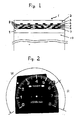
- Figs. 1 and 2 The image strength and adhesion of the meter panel thus obtained are shown in Table 3 and a vertical cross-sectional view and plane view of the meter panel are shown in Figs. 1 and 2.
- figs. 1 is a meter panel
- 2 is a photo-polymerizable image-receiving layer
- 3,4,5,6, are black, cyan, magenta and yellow image layers
- 9 is a photo-polymerizable adhesive layer
- 10 is a permanet support.
- a liquid photo-polymerizable adhesive having the following composition was applied to a polycarbonate resin plate which was the rigid light-transmitting permanent support to form a layer having a thickness of 5 ⁇ m:
- Liquid photo-polymerizable adhesive Trimethylolpropane triacrylate 50.0 g
- the image layer of the image-receiving material having the black, cyan, magenta and yellow color separation images formed in the same manner as that of Example 1 was superposed on the liquid adhesive layer of the polycarbonate and they were pressed with a roller so that no bubbles were formed between them.
- An image-receiving material having black, cyan, magenta and yellow images transferred thereonto prepared in the same manner as that of Example 1 was superposed on a polycarbonate resin plate which was a rigid light-transmitting permanent support so that the plate is brought into contact with the image layer.
- the lamination was conducted under the same conditions as those of Example 1 to form a laminate.
- a polycarbonate resin plate which was the rigid light-transmitting permanent support was laminated with a heat-sensitive adhesive sheet under the same conditions as those of Example 1.
- the image-receiving material having the black, cyan, magenta and yellow images transferred thereonto prepared in the same manner as that of Example 1 was placed on the polycarbonate resin plate so that the image layer was brought into contact with the heat-sensitive adhesive sheet.
- the lamination was conducted under the same conditions as those of Example 1 to form a laminate.
- the pencil hardness was determined according to JIS D-0212.
- the image on the meter panel was cross-cut to form squares (1 mm x 1 mm) with an NT cutter, it was peeled off with Nitto Polyester adhesive tape (No. 31; a product of Nitto Denko Co., Ltd.) and the degree of the image remaining on the support was examined according to JIS D-0202.
- the image on the meter panel was cross-cut to form squares (1 mm x 1 mm) with an NT cutter and it was left to stand at 60 °C at a relative humidity of 95% for 120 h. The peeling off and expansion in the image part were examined.
Landscapes
- Physics & Mathematics (AREA)
- General Physics & Mathematics (AREA)
- Photosensitive Polymer And Photoresist Processing (AREA)
- Laminated Bodies (AREA)
Applications Claiming Priority (2)
| Application Number | Priority Date | Filing Date | Title |
|---|---|---|---|
| JP25420989 | 1989-09-29 | ||
| JP254209/89 | 1989-09-29 |
Publications (2)
| Publication Number | Publication Date |
|---|---|
| EP0420276A2 true EP0420276A2 (fr) | 1991-04-03 |
| EP0420276A3 EP0420276A3 (en) | 1991-08-21 |
Family
ID=17261773
Family Applications (1)
| Application Number | Title | Priority Date | Filing Date |
|---|---|---|---|
| EP19900118697 Withdrawn EP0420276A3 (en) | 1989-09-29 | 1990-09-28 | Display and process for production thereof |
Country Status (3)
| Country | Link |
|---|---|
| US (1) | US5053300A (fr) |
| EP (1) | EP0420276A3 (fr) |
| JP (1) | JP2696264B2 (fr) |
Families Citing this family (7)
| Publication number | Priority date | Publication date | Assignee | Title |
|---|---|---|---|---|
| US5266427A (en) * | 1988-10-18 | 1993-11-30 | Nippondenso Co., Ltd. | Display board and method for producing the same |
| JP2648004B2 (ja) * | 1990-09-03 | 1997-08-27 | インダストリアル・テクノロジー・リサーチ・インステイテュート | エッチング耐性パターン形成方法 |
| JP3319651B2 (ja) * | 1994-04-26 | 2002-09-03 | 富士写真フイルム株式会社 | 感光性転写シート |
| JP4690721B2 (ja) * | 2004-12-28 | 2011-06-01 | 株式会社槌屋 | 光透過性表示部を有する接着性表示シート及びその製造方法 |
| US20080233053A1 (en) * | 2005-02-07 | 2008-09-25 | Pharmalight Inc. | Method and Device for Ophthalmic Administration of Active Pharmaceutical Ingredients |
| JP6107300B2 (ja) * | 2013-03-27 | 2017-04-05 | 日立化成株式会社 | 接着物の製造方法及び感光性接着剤シート |
| JP6432620B2 (ja) * | 2017-03-07 | 2018-12-05 | 日立化成株式会社 | 接着物の製造方法及び感光性接着剤シート |
Family Cites Families (5)
| Publication number | Priority date | Publication date | Assignee | Title |
|---|---|---|---|---|
| GB625425A (en) * | 1946-05-04 | 1949-06-28 | William Soby | Improvements relating to producing designs on support members |
| JPS5997140A (ja) * | 1982-11-26 | 1984-06-04 | Fuji Photo Film Co Ltd | カラ−プル−フイングシ−トの製法 |
| JPH0719052B2 (ja) * | 1985-02-19 | 1995-03-06 | 富士写真フイルム株式会社 | 画像形成法 |
| JPH0623845B2 (ja) * | 1986-06-23 | 1994-03-30 | 富士写真フイルム株式会社 | 感光性受像シート材料及び画像転写方法 |
| DE68927791T2 (de) * | 1988-10-18 | 1997-06-12 | Nippon Denso Co | Anzeigetafel und Herstellungsverfahren |
-
1990
- 1990-09-28 EP EP19900118697 patent/EP0420276A3/en not_active Withdrawn
- 1990-09-28 US US07/590,273 patent/US5053300A/en not_active Expired - Lifetime
- 1990-09-28 JP JP2259205A patent/JP2696264B2/ja not_active Expired - Fee Related
Also Published As
| Publication number | Publication date |
|---|---|
| JPH03228087A (ja) | 1991-10-09 |
| JP2696264B2 (ja) | 1998-01-14 |
| US5053300A (en) | 1991-10-01 |
| EP0420276A3 (en) | 1991-08-21 |
Similar Documents
| Publication | Publication Date | Title |
|---|---|---|
| US4482625A (en) | Process for preparing a color proofing sheet | |
| US4304836A (en) | Surlay proofing method | |
| JPS5914736B2 (ja) | 多色テストプリントの製法 | |
| US5856064A (en) | Dry peel-apart imaging or proofing system | |
| EP0365358B1 (fr) | Fabrication de matériaux pour couches réceptrices pour développement par arrachement, système d'épreuve en couleurs à couche unique | |
| US5534905A (en) | Thermal-transfer recording process | |
| US5053300A (en) | Display and process for production thereof | |
| JPS63147154A (ja) | 画像形成材料 | |
| KR19980080589A (ko) | 폴리비닐 아세탈 광접착층을 보유하는 음각 작용성이고 박리현상가능한 단일 시이트 착색 인화 시스템 | |
| JPH02123360A (ja) | 画像形成材料 | |
| JPH0658537B2 (ja) | 受像シ−ト | |
| US6177234B1 (en) | Process and preparation of monochrome and polychromatic color proofs from high resolution color separations using image carriers having a specified roughness | |
| JPS63147162A (ja) | プル−フイングシ−トによる画像形成方法 | |
| US5055375A (en) | Method of image formation using heated rollers | |
| JPS63282729A (ja) | 着色像を形成する方法、および該方法により製造された製品 | |
| JPH0258058A (ja) | 画像形成材料 | |
| JP2629043B2 (ja) | 画像形成材料 | |
| JPH06332186A (ja) | 画像形成材料 | |
| JPH06175361A (ja) | 画像形成材料 | |
| JPH04172352A (ja) | 着色画像形成材料 | |
| JPH06332187A (ja) | 画像形成材料 | |
| JPH10123704A (ja) | 画像形成材料 | |
| JPH03174159A (ja) | 画像形成材料及び転写像形成方法 | |
| JPH06210973A (ja) | 感光性画像形成シート | |
| WO1996010216A1 (fr) | Systeme de tirage d'epreuve pour verification des couleurs en mode surimpression a l'aide d'un procede negatif ou positif |
Legal Events
| Date | Code | Title | Description |
|---|---|---|---|
| PUAI | Public reference made under article 153(3) epc to a published international application that has entered the european phase |
Free format text: ORIGINAL CODE: 0009012 |
|
| AK | Designated contracting states |
Kind code of ref document: A2 Designated state(s): DE FR GB IT |
|
| PUAL | Search report despatched |
Free format text: ORIGINAL CODE: 0009013 |
|
| AK | Designated contracting states |
Kind code of ref document: A3 Designated state(s): DE FR GB IT |
|
| 17P | Request for examination filed |
Effective date: 19920205 |
|
| 17Q | First examination report despatched |
Effective date: 19950802 |
|
| STAA | Information on the status of an ep patent application or granted ep patent |
Free format text: STATUS: THE APPLICATION IS DEEMED TO BE WITHDRAWN |
|
| 18D | Application deemed to be withdrawn |
Effective date: 19970207 |