EP0425312A2 - Assemblage moteur dans l'axe d'un entraînement de disque - Google Patents
Assemblage moteur dans l'axe d'un entraînement de disque Download PDFInfo
- Publication number
- EP0425312A2 EP0425312A2 EP90311777A EP90311777A EP0425312A2 EP 0425312 A2 EP0425312 A2 EP 0425312A2 EP 90311777 A EP90311777 A EP 90311777A EP 90311777 A EP90311777 A EP 90311777A EP 0425312 A2 EP0425312 A2 EP 0425312A2
- Authority
- EP
- European Patent Office
- Prior art keywords
- spindle
- spindle hub
- disk
- fixed shaft
- disk drive
- Prior art date
- Legal status (The legal status is an assumption and is not a legal conclusion. Google has not performed a legal analysis and makes no representation as to the accuracy of the status listed.)
- Granted
Links
Images


Classifications
-
- G—PHYSICS
- G11—INFORMATION STORAGE
- G11B—INFORMATION STORAGE BASED ON RELATIVE MOVEMENT BETWEEN RECORD CARRIER AND TRANSDUCER
- G11B19/00—Driving, starting, stopping record carriers not specifically of filamentary or web form, or of supports therefor; Control thereof; Control of operating function ; Driving both disc and head
- G11B19/02—Control of operating function, e.g. switching from recording to reproducing
- G11B19/14—Control of operating function, e.g. switching from recording to reproducing by sensing movement or position of head, e.g. means moving in correspondence with head movements
-
- G—PHYSICS
- G11—INFORMATION STORAGE
- G11B—INFORMATION STORAGE BASED ON RELATIVE MOVEMENT BETWEEN RECORD CARRIER AND TRANSDUCER
- G11B19/00—Driving, starting, stopping record carriers not specifically of filamentary or web form, or of supports therefor; Control thereof; Control of operating function ; Driving both disc and head
- G11B19/20—Driving; Starting; Stopping; Control thereof
- G11B19/2009—Turntables, hubs and motors for disk drives; Mounting of motors in the drive
Definitions
- the present invention relates to a spindle motor assembly for use in a disk drive, and to a disk drive including a spindle motor assembly.
- Disk drives for modern desk top computer systems record and re-produce information on a recording medium.
- the medium generally takes the form of a stack of circular information storage disks having a multiplicity of concentric tracks.
- Conventional Winchester type disk drives include a disk stack having one or more vertically aligned information storage disks which are journaled about the hub portion of a single spindle assembly. Each disk has at least one associated magnetic head that is adapted to transfer information between the disk and an external system.
- the heads are typically arranged to move back and forth radially across the disks and a spindle motor assembly is provided to rotate the disks. The movements of the spindle and the magnetic heads co-operate to allow random access to any portion of each disk.
- FIG. 1 A conventional spindle motor assembly used in disk drive applications is shown in Figure 1.
- traditional spindle motor assemblies typically include a non-rotating spindle flange 100 that is securely fastenable to the drive housing.
- a rotatable spindle hub 106 is journaled about the spindle flange 100, and is carried by an elongated rotatable shaft 112 that extends co-axially with the hub and flange.
- a pair of spaced apart ball bearings 115 are coupled between the shaft and the flange to allow the spindle shaft 112 to rotate freely within the confines of the spindle flange 100.
- a motor 118 is disposed directly underneath the spindle arrangement such that the motor components are located outside of the disk housing when the drive is assembled.
- the motor 118 includes a stator assembly 121 and a rotor assembly 124.
- the stator assembly includes a plurality of lamination stacks each having a winding wrapped there-about.
- the rotor assembly 124 is attached to the spindle shaft by a lower hub 127, and includes a cup shaped rotor cap 130 having a raised annular flange portion 132 with a plurality of magnets 133 disposed about the interior surface of the flange portion.
- a cup shaped rotor cap 130 having a raised annular flange portion 132 with a plurality of magnets 133 disposed about the interior surface of the flange portion.
- Such an arrangement does not readily lend itself to miniaturisation when used in conventional disk drives, since it has numerous components having large air spaces therebetween. Further, mere reduction in component size tends to weaken the component structure, which tends to lead to faster wear and to lower the mechanical resonance frequencies of the motor. Such mechanical resonances generate acoustic noises which are irritating to users and therefore are preferably minimised.
- One spindle motor design that has better space utilisation than the traditional design incorporates an in-hub motor, as shown in Figure 2.
- a fixed shaft 150 is provided about which a spindle hub 152 is journaled.
- a pair of spaced apart ball bearings 154, 155 are mounted directly between the fixed shaft and the rotatable hub 152.
- the rotor magnets 156 are carried directly by the spindle hub 152, and the stator windings 157 are disposed between the spaced apart ball bearings 154 and 155.
- FIG. 3 Yet another recent approach is shown in Figure 3.
- a fixed shaft 170 is again used and the spindle hub 152 has a cup shaped radial cross section.
- the bearings 174, 175 are placed between the shaft 170 and an inner wall of the spindle hub 152.
- a motor housing base 172 which is also cup shaped, has a large U-shaped trough 176 outside the inner wall of the spindle hub 172, and motor components are positioned within the enlarged trough 176.
- the rotor magnets 178 are supported on an inner surface of an outer wall of the spindle hub, while the stator windings 181 are carried by a support ring 183 on a wall 171 extending upward from the motor housing base within the U-shaped trough. While such an arrangement allows adequately sized bearings and stator windings, it requires a disk with a large inner diameter, since the hub must be quite large.
- a spindle motor assembly for a disk drive, comprising a fixed shaft, a spindle hub journaled co-axially for rotation about the fixed shaft, the spindle hub having a flange portion for supporting at least one disk, a pair of spaced apart bearings for rotably coupling the spindle hub to the fixed shaft, each said bearing having an inner race secured to the fixed shaft and an outer race secured to an inner surface of the spindle hub, magnet means carried by the spindle hub, the magnet means having a plurality of poles and forming a rotor portion of the spindle motor, and stator means having plurality of fixed windings for co-operating with the magnet means to rotate the spindle hub with respect to the shaft, characterised in that the magnet means are carried by an outer surface of the spindle hub and are located adjacent at least one of the pair of spaced apart bearings.
- the invention provides a spindle motor assembly that utilises a fixed shaft and places the motor components on the outside wall of the spindle hub directly below a flange for supporting at least one disk.
- the disclosed spindle motor assembly includes the fixed shaft having the spindle hub journaled co-axially there-about.
- the spindle hub has several distinct portions including an enlarged thickness flange portion, which supports the drive's disk stack, and a reduced thickness rotor carrying portion located adjacent the side of the flange opposite the disk stack.
- a pair of spaced apart bearings rotatably couple the spindle hub to the fixed shaft, with each of the bearings having its inner race secured to the fixed shaft and its outer race secured to the inner surface of the spindle hub.
- the rotor assembly includes a magnet arrangement having a number of poles, and is carried by the outer surface of the rotor carrying portion of the spindle hub.
- the stator has a plurality of fixed windings that co-operate with the rotor to rotate the spindle hub (and thus the disk stack).
- the stator assembly is preferably substantially positioned within the space defined by the hub's flange portion and rotor carrying portion.
- Hall effect sensors are set in a fixed place adjacent the rotor magnet arrangement to detect the passage of the poles to control commutation.
- the magnet is magnetised to establish two non-parallel flux regions for each pole.
- a high torque spindle motor assembly may thus be provided, which is rugged, easy to manufacture, and has a small parts count.
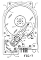
- a disk stack 10 is journaled about a spindle motor assembly 15 within a housing 5 having upper and lower casing members 7 and 9, respectively.
- the disk stack 10 includes a plurality of information storage disks 10 with a spacer 23 disposed between adjacent disks 10 to maintain their spacing. In the embodiment shown in Figure 4, only two information storage disks are used. However, it should be appreciated that any member of information storage disks may be incorporated into the disk stack with spacers between each pair of adjacent disks.
- a disk clamp 25 positioned above the top information storage disk firmly secures the disk stack to the hub portion of the spindle motor assembly 15.
- a head positioner assembly 28 is rotatably mounted between the upper and lower casings 7, 9 in one corner of the housing 5.
- the head positioner assembly 28 carries a plurality of head arm flexures 30 that each carry a magnetic read/write or servo head 32 for reading information from and writing information onto the magnetic disks 10.
- the head arms are each attached to the head positioner assembly 28 by individual flexure mounts 38.
- a voice coil motor 40 is adapted precisely to rotate the head positioner assembly back and forth such that the data and servo heads move across the magnetic disks.
- a magnetic latch 42 holds the head positioner assembly in place when the disk drive is not in use.
- Each magnetic disk 10 has a multiplicity of concentric circular information storage tracks for recording information.
- the first embodiment of the spindle motor 15 chosen for the purpose of illustration includes a fixed spindle shaft 52 that is secured to the drive housing 5 by a pair of opposing screws 54 and 55. It should be appreciated that an alternative spindle shaft mounting would work as well. By way of example, one end of the shaft could be press fit into a recess in either the upper or lower casing.
- a rotatable spindle hub 60 is co-axially journaled about the spindle shaft 52 and is supported by a pair of spaced apart ball bearings 62.
- the inner and outer races of the ball bearings 62 are fixedly attached, preferably adhesively bonded, to the spindle shaft and the inner surface of the spindle hub 60, respectively, and allow the spindle hub 60 to rotate freely about the spindle shaft 52.
- the ball bearings 62 are separated by a spacer 63 which is used axially to pre-load the bearings during fabrication.
- the spindle hub 60 has substantially cylindrical walls, which define an inner bore 65 that receives the spindle shaft 52 and the ball bearings 62.
- the wall is divided into three separate sections, and has an annular post ring 67 for supporting the disk clamp 25.
- the wall includes a thick upper section 70, an enlarged middle flange section 72, and a relatively thin magnet supporting lower section 74.
- a multiplicity of screw holes extend downward from the top portion of the hub through the upper and middle flange sections of the wall to receive the clamp screws 75 to secure the disk clamp 25 to the spindle motor 15.
- a small cover plate 76 is journaled about the hub below the flange 72 to seal the screw holes to prevent dust particles and metal flakes within the motor assembly from escaping into the main disk chamber.
- the flange 72 provides a support surface 77 upon which the information storage disks 10 can rest. Thus, the disk stack is held in place between the disk clamp 25 and the support surface 77 of the flange 72.
- An iron magnet support ring 80 is fixedly attached, preferably adhesively bonded, to the lower hub section 74.
- the spindle hub 60 is formed of aluminium.
- a ring magnet 82 is fixedly attached to the magnet support ring 80 to firmly secure the magnet to the spindle hub. Since the magnet 82 is carried by the spindle hub 60, it will rotate with the spindle hub and therefore forms the rotor portion of the spindle motor assembly.
- the disk stack 8 contains only two information storage disks, and the housing 5 is designed to minimise the drive's profile and the space consumed.
- the lower casing member 9 includes a cylindrical well recess 90 adapted to receive the stator and rotor portions of the spindle motor 15.
- a multiplicity of stator windings 92 are wound about ferric lamination stacks 94, which in turn are adhesively bonded to the inner walls of the well recess 90.
- a conventional ferro-fluidic seal 96 incorporating a fluid magnetic shield is positioned within the inner bore 65 of the spindle hub 60 to provide a seal against contamination by air flow from the bearing area to the head disk area.
- FIG. 5 an alternative embodiment of the invention will be described using like numbers to denote like parts.
- a Hall effect sensor arrangement is provided that monitors the rotations of the rotor to control commutation.
- Figure 5 also shows slightly different embodiments of several other components of the spindle motor as well to exemplify a few of the modifications contemplated within the scope of the invention.
- a single information storage disk 10 is contemplated, and thus the upper section 70 of the spindle hub is greatly reduced.
- a base plate 200 is provided which is coupled to part of the disk housing 5 by a plurality of screws, and which allows the stator and Hall effect sensor arrangement to be installed as a separate unit.
- Hall effect sensors 205 are mounted on a printed circuit board 207 that is carried by the base plate 200 and are positioned immediately below the ring magnet 82. Thus, every time a pole passes a sensor, the sensor detects the change of flux and so informs a controller (not shown) which is used to control commutation of the motor.
- a controller not shown
- Hall effect sensors may be situated about the base plate to detect incremental movements. By way of example, in the embodiment chosen for the purposes of illustration, three Hall effect sensors are used which are disposed at 120° angles with respect to one another.
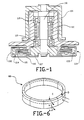
- the ring magnet 82 would typically be magnetised to provide the strongest field perpendicular to its outer surface (as suggested by flux lines A and B in Figure 6).
- Hall effect sensors mounted as described would typically be able to detect enough of a flux change to note the passage of a pole
- the magnetic rings may be magnetised such that each pole emits a field having two different orientations as seen in Figure 6.
- the lowest portion of the magnet immediately adjacent the Hall effect sensors is magnetised such that its flux lines C and D are parallel to the magnet's outer surface as shown in Figure 6, while the vast majority of the ring magnet 82 is magnetised in the traditional manner.
- the spindle flange in the described embodiment turns down to overlap a protruding ring 211 that extends upwardly from the base.
- the overlap serves better to isolate the spindle assembly to reduce the transfer of dust particles and metallic flakes between the air space about the spindle motor components and the air space within the main drive compartments.
- a printed circuit cable 215 extends from the printed circuit board 207 to the controller. The printed circuit cable is clamped to the base plate 200 by clamp 217.
- the actual number of poles in the rotor's ring magnet 82 and the number of windings in the stator may be widely varied depending upon the requirements of the motor.
- the ring magnet includes eight poles and the stator includes twelve windings 92.
- the described spindle motor structure has several advantages over conventional designs. Initially, the described structure is inherently very stiff which tends to reduce the drive's susceptibility to the excitation of structural mechanical resonances which, in turn, often produce undesirable acoustic noise.
- the design has a low profile, which saves space in the continuing quest to reduce the required overall drive size. It can also provide a high torque to a compact, light weight hub assembly, which allows rapid information access.
- the resultant design has a lower parts count than traditional spindle motors, which simplifies manufacturing and reduces the overall spindle motor cost.
Landscapes
- Rotational Drive Of Disk (AREA)
- Permanent Magnet Type Synchronous Machine (AREA)
- Brushless Motors (AREA)
Applications Claiming Priority (2)
| Application Number | Priority Date | Filing Date | Title |
|---|---|---|---|
| US42467389A | 1989-10-27 | 1989-10-27 | |
| US424673 | 1989-10-27 |
Publications (3)
| Publication Number | Publication Date |
|---|---|
| EP0425312A2 true EP0425312A2 (fr) | 1991-05-02 |
| EP0425312A3 EP0425312A3 (fr) | 1991-05-15 |
| EP0425312B1 EP0425312B1 (fr) | 1996-06-12 |
Family
ID=23683458
Family Applications (1)
| Application Number | Title | Priority Date | Filing Date |
|---|---|---|---|
| EP90311777A Expired - Lifetime EP0425312B1 (fr) | 1989-10-27 | 1990-10-26 | Assemblage moteur dans l'axe d'un entraînement de disque |
Country Status (7)
| Country | Link |
|---|---|
| US (3) | US5352947A (fr) |
| EP (1) | EP0425312B1 (fr) |
| JP (2) | JPH03212148A (fr) |
| KR (1) | KR950003566B1 (fr) |
| CA (1) | CA2027225A1 (fr) |
| DE (1) | DE69027396T2 (fr) |
| SG (1) | SG47719A1 (fr) |
Cited By (6)
| Publication number | Priority date | Publication date | Assignee | Title |
|---|---|---|---|---|
| EP0613134A1 (fr) * | 1993-02-23 | 1994-08-31 | Minebea Kabushiki-Kaisha | Unité à disque magnétique |
| EP0685843A1 (fr) * | 1994-06-03 | 1995-12-06 | Hewlett-Packard Company | Unité de disque de bas profil, entraîné par moteur, pour appareil d'enregistrement/reproduction |
| DE19644755A1 (de) * | 1995-10-31 | 1997-05-07 | Fujitsu Ltd | Struktur von Spindelmotor in einem Plattenlaufwerk und Verfahren zum Montieren des Plattenlaufwerks |
| EP0869494A1 (fr) * | 1997-04-01 | 1998-10-07 | Papst Licensing GmbH | Dispositif de mémoire à disques avec couple axial et accélération améliorés |
| RU2137217C1 (ru) * | 1995-05-22 | 1999-09-10 | Интернэшнл Бизнес Машинз Корпорейшн | Поворотный подшипник |
| US6005746A (en) * | 1997-04-01 | 1999-12-21 | Papst Licensing Gmbh & Co. Kg | Disk storage device with improved spindle torque and acceleration |
Families Citing this family (34)
| Publication number | Priority date | Publication date | Assignee | Title |
|---|---|---|---|---|
| US5528092A (en) * | 1992-06-23 | 1996-06-18 | Nippon Corporation | Spindle motor |
| US5459361A (en) * | 1992-07-14 | 1995-10-17 | Nippon Densan Corporation | Spindle motor |
| US5519270A (en) * | 1992-08-19 | 1996-05-21 | Fujitsu Limited | Spindle motor and disk drive having the same |
| US5698919A (en) * | 1992-11-09 | 1997-12-16 | Minebea Kabushiki-Kaisha | Integral bearing type electric motor |
| US5596235A (en) * | 1993-02-22 | 1997-01-21 | Nidec Corporation | Spindle motor with seal structure |
| US5555211A (en) * | 1995-01-23 | 1996-09-10 | Quantum Corporation | Improved spindle shaft for attaching a cover in a disk drive |
| US5694268A (en) * | 1995-02-10 | 1997-12-02 | Seagate Technology, Inc. | Spindle motor having overmolded stator |
| US5619389A (en) * | 1995-02-10 | 1997-04-08 | Seagate Technology, Inc. | Stator isolation for spindle motor |
| US5742450A (en) * | 1995-03-08 | 1998-04-21 | International Business Machines Corporation | Disk drive spindle motor with radial gap and field generating coils interconnected by ring flux guide |
| JPH11511638A (ja) * | 1995-08-18 | 1999-10-05 | インターナショナル マシナリー コーポレーション | 永久磁石ロータ交流発電機 |
| US5633545A (en) * | 1995-12-06 | 1997-05-27 | International Business Machines Corporation | Disk drive in-hub radial-gap spindle motor with coils generating axial fields |
| US5705868A (en) * | 1996-04-25 | 1998-01-06 | Seagate Technology, Inc. | Spindle motor connector having supported electrical leads |
| US6535475B1 (en) * | 1996-10-09 | 2003-03-18 | Samsung Electronics Co., Ltd. | Disk player, and turntable incorporating self-compensating dynamic balancer, clamper incorporating self-compensating dynamic balancer and spindle motor incorporating self-compensating dynamic balancer adopted for disk player |
| US6271988B1 (en) | 1997-01-04 | 2001-08-07 | Papst Licensing Gmbh & Co. Kg | Disk storage device with improved spindle torque and acceleration |
| US6344946B1 (en) | 1997-04-01 | 2002-02-05 | Papst Licensing Gmbh | Disk storage device with improved spindle torque and acceleration |
| US6356405B1 (en) | 1998-05-22 | 2002-03-12 | Seagate Technology Llc | Lubricant control in disc drive |
| US6104570A (en) * | 1998-09-18 | 2000-08-15 | Seagate Technology, Inc. | Disc drive spindle motor having tuned stator with adhesive grooves |
| US6545974B1 (en) | 1998-11-18 | 2003-04-08 | Seagate Technology Llc | Disc media and methods for fabricating |
| WO2000062404A1 (fr) * | 1999-04-07 | 2000-10-19 | International Business Machines Corporation | Moteur a axe et dispositif pour disque |
| US6702592B1 (en) | 1999-12-03 | 2004-03-09 | Seagate Technology Llc | Printed circuit board assembly with secondary side rigid electrical pin to mate with compliant contact |
| JP3804854B2 (ja) * | 2000-01-07 | 2006-08-02 | 日本ビクター株式会社 | 回転記録媒体駆動装置及びその製造方法 |
| US6930420B2 (en) * | 2001-03-21 | 2005-08-16 | Nsk Ltd. | Motor |
| US20030006658A1 (en) * | 2001-06-29 | 2003-01-09 | Gunhee Jang | Ultra-slim structure of disk-spindle motor |
| US6545382B1 (en) * | 2002-03-29 | 2003-04-08 | Western Digital Technologies, Inc. | Spindle motor including stator with magnetic flux guides |
| DE10259426A1 (de) * | 2002-12-06 | 2004-06-24 | Prodema Antriebstechnik Gmbh & Co. Kg | Gleichstrommotor, insbesondere für maritime Zwecke |
| JP2004266891A (ja) * | 2003-02-25 | 2004-09-24 | Matsushita Electric Ind Co Ltd | 動圧気体軸受モータ |
| US6961210B2 (en) * | 2003-03-28 | 2005-11-01 | Esgw Holdings Limited | Data storage device with a low profile spindle motor |
| US7116091B2 (en) * | 2004-03-04 | 2006-10-03 | Zircon Corporation | Ratiometric stud sensing |
| JP4343100B2 (ja) * | 2004-12-28 | 2009-10-14 | 日本電産株式会社 | モータユニットおよび記録ディスク駆動装置 |
| JP2007143379A (ja) * | 2005-11-22 | 2007-06-07 | Nippon Densan Corp | ブラシレスモータ |
| JP2009254044A (ja) * | 2008-04-02 | 2009-10-29 | Nippon Densan Corp | モータ |
| JP2012104169A (ja) * | 2010-11-08 | 2012-05-31 | Nippon Densan Corp | モータユニットおよびディスク駆動装置 |
| US20150263585A1 (en) * | 2014-03-13 | 2015-09-17 | Seagate Technology Llc | Fastener coupling radially inside a stator assembly |
| US9343101B2 (en) | 2014-06-19 | 2016-05-17 | HGST Netherlands B.V. | Hard disk drive low profile disk clamp to tied-shaft motor assembly |
Family Cites Families (31)
| Publication number | Priority date | Publication date | Assignee | Title |
|---|---|---|---|---|
| US4285016A (en) * | 1979-06-04 | 1981-08-18 | Microcomputer Systems Corp. | Disc, tape and hybrid disc-tape memory apparatus and drive assembly |
| CH670323A5 (fr) * | 1985-03-30 | 1989-05-31 | Papst Motoren Gmbh & Co Kg | |
| JPH036149Y2 (fr) * | 1981-01-13 | 1991-02-15 | ||
| JPS5917019A (ja) | 1982-07-20 | 1984-01-28 | Toshiba Corp | 回転体支持装置 |
| US4488076A (en) * | 1982-09-30 | 1984-12-11 | Applied Motion Products, Inc. | Tachometer assembly for magnetic motors |
| US4494028A (en) * | 1982-09-30 | 1985-01-15 | Rotron Incorporated | Integral coaxial commutation and rotor magnets and apparatus and method for making same |
| EP0124547A1 (fr) * | 1982-11-01 | 1984-11-14 | Storage Technology Partners Ii | Moteur sans balai a courant continu avec cuvette d'aimant inversee |
| JPS6026676U (ja) * | 1983-07-28 | 1985-02-22 | 日本精工株式会社 | 磁気ディスク記憶装置 |
| DE3434965A1 (de) * | 1983-09-22 | 1985-04-04 | Papst-Motoren GmbH & Co KG, 7742 St Georgen | Gekapselter kleinstmotor |
| JPS60173770A (ja) * | 1984-02-17 | 1985-09-07 | Nippon Telegr & Teleph Corp <Ntt> | 磁気デイスク装置 |
| JPH0782699B2 (ja) * | 1984-06-01 | 1995-09-06 | パプスト ライセンシング ゲーエムベーハー | デイスク駆動装置 |
| CA1266877A (fr) * | 1984-09-13 | 1990-03-20 | Erich Rabe | Machine a courant continu commutee electroniquement et son usage |
| JPS61154460A (ja) * | 1984-12-27 | 1986-07-14 | Mazda Motor Corp | エンジンの始動発電装置 |
| US4633110A (en) * | 1985-03-20 | 1986-12-30 | Rotron, Inc. | Motor with stator on printed circuit assembly |
| JPH0629610B2 (ja) * | 1985-04-19 | 1994-04-20 | 株式会社日立製作所 | 磁気デイスク装置のスピンドル機構 |
| US4686592A (en) * | 1985-05-02 | 1987-08-11 | Carroll Thomas D | Disk drive assembly |
| US4712146A (en) | 1985-06-04 | 1987-12-08 | Plus Development Corporation | Thin and compact micro-Winchester head and disk assembly |
| ATE54517T1 (de) | 1985-09-23 | 1990-07-15 | Siemens Ag | Elektromotor, insbesondere dauermagneterregter aussenlaeufermotor. |
| US4734606A (en) * | 1985-11-20 | 1988-03-29 | Hajec Chester S | Electric motor with ferrofluid bearing |
| JPH0528594Y2 (fr) | 1986-12-03 | 1993-07-22 | ||
| GB8705656D0 (en) * | 1987-03-10 | 1987-04-15 | Torin Ltd | Dc motors |
| JP2590334B2 (ja) * | 1987-05-08 | 1997-03-12 | 長野日本電産 株式会社 | カップ形ロ−タを有する磁気ディスク駆動用モ−タ |
| JPS63317977A (ja) * | 1987-06-22 | 1988-12-26 | Shinano Totsuki Kk | 磁気ディスク用モ−タの防塵シ−ル構造 |
| US4797762A (en) * | 1987-09-22 | 1989-01-10 | Micropolis Corporation | Stress free winchester drive shaft mounting |
| US4905110A (en) * | 1988-03-25 | 1990-02-27 | Magnetic Peripherals Inc. | Disk drive spindle motor |
| JPH0232731A (ja) * | 1988-07-16 | 1990-02-02 | Chubu Seimitsu:Kk | モータの構造 |
| US4949000A (en) * | 1988-07-18 | 1990-08-14 | Mueller And Smith, Lpa | D.C. motor |
| JP2573035B2 (ja) * | 1988-08-24 | 1997-01-16 | 日本電産株式会社 | スピンドルモータ及びスピンドルモータの製造方法 |
| US5157295A (en) | 1989-01-25 | 1992-10-20 | Conner Peripherals, Inc. | Under-the-hub disk drive spin motor |
| JPH02223365A (ja) * | 1989-02-22 | 1990-09-05 | Sony Corp | スピンドルモータ |
| US4965476A (en) * | 1989-04-20 | 1990-10-23 | Conner Peripherals, Inc. | Stabilized disk drive spin motor |
-
1990
- 1990-10-10 CA CA002027225A patent/CA2027225A1/fr not_active Abandoned
- 1990-10-26 SG SG1996004055A patent/SG47719A1/en unknown
- 1990-10-26 DE DE69027396T patent/DE69027396T2/de not_active Expired - Fee Related
- 1990-10-26 EP EP90311777A patent/EP0425312B1/fr not_active Expired - Lifetime
- 1990-10-26 KR KR1019900017219A patent/KR950003566B1/ko not_active Expired - Fee Related
- 1990-10-26 JP JP2290636A patent/JPH03212148A/ja active Pending
-
1991
- 1991-08-06 US US07/745,983 patent/US5352947A/en not_active Expired - Lifetime
-
1996
- 1996-10-24 US US08/738,467 patent/US6316853B1/en not_active Expired - Fee Related
- 1996-12-19 JP JP1996012941U patent/JP2559138Y2/ja not_active Expired - Fee Related
-
2001
- 2001-08-13 US US09/929,548 patent/US20020093256A1/en not_active Abandoned
Cited By (11)
| Publication number | Priority date | Publication date | Assignee | Title |
|---|---|---|---|---|
| EP0613134A1 (fr) * | 1993-02-23 | 1994-08-31 | Minebea Kabushiki-Kaisha | Unité à disque magnétique |
| US6078466A (en) * | 1993-02-23 | 2000-06-20 | Minebea Kabushiki-Kaisha | Magnetic disk unit |
| EP0685843A1 (fr) * | 1994-06-03 | 1995-12-06 | Hewlett-Packard Company | Unité de disque de bas profil, entraîné par moteur, pour appareil d'enregistrement/reproduction |
| RU2137217C1 (ru) * | 1995-05-22 | 1999-09-10 | Интернэшнл Бизнес Машинз Корпорейшн | Поворотный подшипник |
| DE19644755A1 (de) * | 1995-10-31 | 1997-05-07 | Fujitsu Ltd | Struktur von Spindelmotor in einem Plattenlaufwerk und Verfahren zum Montieren des Plattenlaufwerks |
| US5942820A (en) * | 1995-10-31 | 1999-08-24 | Fujitsu Limited | Structure of spindle motor in a disk drive and method of assembling the disk drive |
| DE19644755B4 (de) * | 1995-10-31 | 2005-07-28 | Fujitsu Ltd., Kawasaki | Struktur eines Plattenmotors in einem Plattenlaufwerk |
| EP0869494A1 (fr) * | 1997-04-01 | 1998-10-07 | Papst Licensing GmbH | Dispositif de mémoire à disques avec couple axial et accélération améliorés |
| WO1998044500A1 (fr) * | 1997-04-01 | 1998-10-08 | Papst Licensing Gmbh | Unite de disque possedant un couple et une acceleration de pivot ameliores |
| US5877916A (en) * | 1997-04-01 | 1999-03-02 | Papst; Georg F. | Disk storage device with stator-rotor positioning providing improved spindle torque and acceleration |
| US6005746A (en) * | 1997-04-01 | 1999-12-21 | Papst Licensing Gmbh & Co. Kg | Disk storage device with improved spindle torque and acceleration |
Also Published As
| Publication number | Publication date |
|---|---|
| US6316853B1 (en) | 2001-11-13 |
| US20020093256A1 (en) | 2002-07-18 |
| US5352947A (en) | 1994-10-04 |
| JPH03212148A (ja) | 1991-09-17 |
| JPH09496U (ja) | 1997-09-19 |
| CA2027225A1 (fr) | 1991-04-28 |
| KR910008698A (ko) | 1991-05-31 |
| JP2559138Y2 (ja) | 1998-01-14 |
| SG47719A1 (en) | 1998-04-17 |
| EP0425312B1 (fr) | 1996-06-12 |
| DE69027396D1 (de) | 1996-07-18 |
| KR950003566B1 (ko) | 1995-04-14 |
| EP0425312A3 (fr) | 1991-05-15 |
| DE69027396T2 (de) | 1996-10-10 |
Similar Documents
| Publication | Publication Date | Title |
|---|---|---|
| EP0425312B1 (fr) | Assemblage moteur dans l'axe d'un entraînement de disque | |
| US5668427A (en) | Spindle motor having recessed stator coils | |
| US4814652A (en) | Disk drive motor with thermally matched parts | |
| US4805055A (en) | Winchester disc drive actuator structure | |
| US5666239A (en) | Laminated base deck for a disc drive | |
| US4905110A (en) | Disk drive spindle motor | |
| US4928029A (en) | In-spindle motor assembly for disk drive and method for fabricating | |
| EP0535018B1 (fr) | Moteur d'entrainement a bruit reduit pour unite de disque | |
| US5528436A (en) | Low profile motor powered disk assembly for a recording/reproducing device | |
| US20080130169A1 (en) | Spindle motor and disk device provided with the same | |
| US8476793B2 (en) | Stiffener tab for a spindle motor base plate | |
| US7190549B2 (en) | Slim spindle motor and micro-drive apparatus comprising the same | |
| US5606475A (en) | Magnetic disc drive motor including a fixed shaft having mounted thereon a lower bearing member with a portion for mounting a rotor | |
| US5400197A (en) | Disc drive spindle motor | |
| US4829657A (en) | In-spindle motor assembly for disk drive and method for fabricating the same | |
| US7031116B2 (en) | Moving magnet voice coil motor using Halbach arrays | |
| US5726829A (en) | Axial spindle motor for hard disk drive assembly | |
| US7550883B2 (en) | Rotor hub, spindle motor, and recording disk driving apparatus | |
| US6876114B2 (en) | Apparatus for reducing spindle motor magnetic drag | |
| US5636084A (en) | Magnetic disk drive motor including a fixed shaft having mounted thereon a ball bearing with a rotor fixed at one end thereof and having a disc abutting the outer ring of the bearing | |
| JPH0246583A (ja) | ディスク装置 | |
| JPH02252180A (ja) | メモリーディスク装置 | |
| US20070271575A1 (en) | Disk Drive Unit | |
| JPH06215532A (ja) | ハードディスクアセンブリ | |
| JP2002329362A (ja) | 小型ディスクドライブ装置 |
Legal Events
| Date | Code | Title | Description |
|---|---|---|---|
| PUAI | Public reference made under article 153(3) epc to a published international application that has entered the european phase |
Free format text: ORIGINAL CODE: 0009012 |
|
| PUAL | Search report despatched |
Free format text: ORIGINAL CODE: 0009013 |
|
| AK | Designated contracting states |
Kind code of ref document: A2 Designated state(s): DE FR GB IT NL |
|
| AK | Designated contracting states |
Kind code of ref document: A3 Designated state(s): DE FR GB IT NL |
|
| 17P | Request for examination filed |
Effective date: 19911021 |
|
| 17Q | First examination report despatched |
Effective date: 19940215 |
|
| RAP1 | Party data changed (applicant data changed or rights of an application transferred) |
Owner name: SEAGATE TECHNOLOGY INTERNATIONAL |
|
| GRAH | Despatch of communication of intention to grant a patent |
Free format text: ORIGINAL CODE: EPIDOS IGRA |
|
| GRAH | Despatch of communication of intention to grant a patent |
Free format text: ORIGINAL CODE: EPIDOS IGRA |
|
| GRAA | (expected) grant |
Free format text: ORIGINAL CODE: 0009210 |
|
| AK | Designated contracting states |
Kind code of ref document: B1 Designated state(s): DE FR GB IT NL |
|
| REF | Corresponds to: |
Ref document number: 69027396 Country of ref document: DE Date of ref document: 19960718 |
|
| ET | Fr: translation filed | ||
| ITF | It: translation for a ep patent filed | ||
| PGFP | Annual fee paid to national office [announced via postgrant information from national office to epo] |
Ref country code: FR Payment date: 19960926 Year of fee payment: 7 |
|
| PGFP | Annual fee paid to national office [announced via postgrant information from national office to epo] |
Ref country code: NL Payment date: 19960930 Year of fee payment: 7 |
|
| PLBE | No opposition filed within time limit |
Free format text: ORIGINAL CODE: 0009261 |
|
| STAA | Information on the status of an ep patent application or granted ep patent |
Free format text: STATUS: NO OPPOSITION FILED WITHIN TIME LIMIT |
|
| 26N | No opposition filed | ||
| PG25 | Lapsed in a contracting state [announced via postgrant information from national office to epo] |
Ref country code: FR Free format text: THE PATENT HAS BEEN ANNULLED BY A DECISION OF A NATIONAL AUTHORITY Effective date: 19971031 |
|
| PG25 | Lapsed in a contracting state [announced via postgrant information from national office to epo] |
Ref country code: NL Free format text: LAPSE BECAUSE OF NON-PAYMENT OF DUE FEES Effective date: 19980501 |
|
| NLV4 | Nl: lapsed or anulled due to non-payment of the annual fee |
Effective date: 19980501 |
|
| REG | Reference to a national code |
Ref country code: FR Ref legal event code: ST |
|
| REG | Reference to a national code |
Ref country code: GB Ref legal event code: 732E |
|
| REG | Reference to a national code |
Ref country code: GB Ref legal event code: IF02 |
|
| PGFP | Annual fee paid to national office [announced via postgrant information from national office to epo] |
Ref country code: DE Payment date: 20031029 Year of fee payment: 14 |
|
| PG25 | Lapsed in a contracting state [announced via postgrant information from national office to epo] |
Ref country code: DE Free format text: LAPSE BECAUSE OF NON-PAYMENT OF DUE FEES Effective date: 20050503 |
|
| PG25 | Lapsed in a contracting state [announced via postgrant information from national office to epo] |
Ref country code: IT Free format text: LAPSE BECAUSE OF NON-PAYMENT OF DUE FEES;WARNING: LAPSES OF ITALIAN PATENTS WITH EFFECTIVE DATE BEFORE 2007 MAY HAVE OCCURRED AT ANY TIME BEFORE 2007. THE CORRECT EFFECTIVE DATE MAY BE DIFFERENT FROM THE ONE RECORDED. Effective date: 20051026 |
|
| PGFP | Annual fee paid to national office [announced via postgrant information from national office to epo] |
Ref country code: GB Payment date: 20071029 Year of fee payment: 18 |
|
| GBPC | Gb: european patent ceased through non-payment of renewal fee |
Effective date: 20081026 |
|
| PG25 | Lapsed in a contracting state [announced via postgrant information from national office to epo] |
Ref country code: GB Free format text: LAPSE BECAUSE OF NON-PAYMENT OF DUE FEES Effective date: 20081026 |