EP0426277A2 - Tuyau à vide pour accélérateur - Google Patents
Tuyau à vide pour accélérateur Download PDFInfo
- Publication number
- EP0426277A2 EP0426277A2 EP90308916A EP90308916A EP0426277A2 EP 0426277 A2 EP0426277 A2 EP 0426277A2 EP 90308916 A EP90308916 A EP 90308916A EP 90308916 A EP90308916 A EP 90308916A EP 0426277 A2 EP0426277 A2 EP 0426277A2
- Authority
- EP
- European Patent Office
- Prior art keywords
- vacuum pipe
- pipe
- sheets
- charged
- accelerator
- Prior art date
- Legal status (The legal status is an assumption and is not a legal conclusion. Google has not performed a legal analysis and makes no representation as to the accuracy of the status listed.)
- Withdrawn
Links
Images


Classifications
-
- H—ELECTRICITY
- H01—ELECTRIC ELEMENTS
- H01J—ELECTRIC DISCHARGE TUBES OR DISCHARGE LAMPS
- H01J41/00—Discharge tubes for measuring pressure of introduced gas or for detecting presence of gas; Discharge tubes for evacuation by diffusion of ions
- H01J41/12—Discharge tubes for evacuating by diffusion of ions, e.g. ion pumps, getter ion pumps
-
- H—ELECTRICITY
- H05—ELECTRIC TECHNIQUES NOT OTHERWISE PROVIDED FOR
- H05H—PLASMA TECHNIQUE; PRODUCTION OF ACCELERATED ELECTRICALLY-CHARGED PARTICLES OR OF NEUTRONS; PRODUCTION OR ACCELERATION OF NEUTRAL MOLECULAR OR ATOMIC BEAMS
- H05H7/00—Details of devices of the types covered by groups H05H9/00, H05H11/00, H05H13/00
- H05H7/14—Vacuum chambers
Definitions
- This invention relates to a vacuum pipe of an accelerator of a charged-particle acceleration and storage system for use in, for example, generating synchrotron radiation light (SOR) and more particularly to such a vacuum pipe having a higher degree of vacuum so as to provide a longer life for charged particles.
- SOR synchrotron radiation light
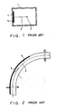
- Figures 1 and 2 illustrate a portion of a conventional SOR generator disclosed, for example, in Japanese unexamined Patent Publication No. SHO 62-276800.
- Figure 1 shows a transverse cross-section of a portion of a vacuum pipe of the SOR generator where deflection magnets (not shown) are disposed
- Figure 2 schematically shows a longitudinal cross-section of the portion of the vacuum pipe shown in Figure 1.
- the reference numeral 1 denotes the vacuum pipe through which charged particles travel along an orbit 2.
- SOR 3 is generated in a direction tangent to the orbit 2 and impinges on the inner wall of the vacuum pipe 1 at a position 4.
- a bulk getter 5 is disposed at the SOR impinging position 4.
- the material for the bulk getter 5 may be, for example, zirconium or a zirconium alloy, such as Zr-Al and Zr-V-Fe.
- the provision of the bulk getter 5 can suppress release of desorbed gas which would occur if the SOR 3 impinged directly on the structural material of the vacuum pipe 1.
- Impurities contained in the bulk getter 5 are ionized by the SOR 3 or by excited electrons generated by the SOR 3, and the thus produced ions diffuse inward of the bulk getter 5, whereby release of gas, desorbed in response to excitation by radiation, from the surface can be greatly suppressed.
- the bulk getter 5 acts as an exhaust pump and, accordingly, can not only completely suppress the release of gas desorbed by radiation-excitation but also adsorb residual gas within the vacuum pipe 1.
- the bulk getter 5 is disposed only at the SOR radiation impinging position 4 and in its vicinity. This arrangement cannot provide adequate suppression of outgassing in other portions where the bulk getter 5 is not disposed and, accordingly, the pressure within the vacuum pipe increases and the life of the stored charged-particles decreases.
- the object of the present invention is to provide an accelerator vacuum pipe free of the above-described defects of the conventional vacuum pipe.
- the vacuum pipe can be maintained at an ultra-high vacuum whereby a long storage life of charged particles can be obtained.
- An accelerator vacuum pipe which defines therein a vacuum space through which charged particles travel in an orbit includes a layer of getter material which can capture residual or generated gas molecules within the pipe.
- the getter material layer is disposed over the entire inner wall of the vacuum pipe at least in a deflection zone where the charged particles are deflected.
- the getter material layer is disposed over the entire inner wall of the entire vacuum pipe.
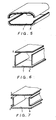
- Figure 3 shows a cross-section of a portion of an accelerator vacuum pipe according to one embodiment of the present invention
- Figures 4(a) and 4(b) shows steps of making the vacuum pipe of Figure 3.
- a sheet 6 of structural material of, for example, stainless steel or aluminum has its one surface coated with a layer 7 of getter material.
- the structural material sheet 6 with the layer 7 of getter material disposed on one surface thereof is bent, with the layer 7 facing inward, in such a manner as to form a pipe shape having a race-track shaped cross-section, as shown in Figure 4(b). Abutting edges of the bent sheets 6 are joined, and reinforcing ribs 8 are attached to, mechanically reinforce the structure.
- the accelerator vacuum pipe 1 shown in Figure 3 results.
- the getter material layer 7 is disposed to overlie the entire inner wall of the pipe, rather than to overlie only portions where SOR impinges as in the aforementioned conventional vacuum pipe.
- the vacuum pipe 1 is heated to activate the getter material. Then the getter material layer 7 adsorbs and exhausts the gas within the vacuum pipe 1 to keep the ultra-high vacuum in the pipe 1.
- Figure 5 shows another embodiment of the vacuum pipe of the present invention.
- Two structural material sheets 6 with respective getter material layers 7 disposed on one surfaces thereof are bent to form two halves, which are butt-joined together along their abutting edges to thereby form a pipe having a race-track shaped cross-section.
- Figure 6 shows a vacuum pipe according to a third embodiment of the present invention, which comprises four structural sheets 6 having respective getter material layers 7 thereon. The four sheets 6 are joined together along their adjoining edges.
- FIG 7 shows a vacuum pipe 1 according to a fourth embodiment of the present invention, which, as the vacuum pipe of Figure 6, comprises four sheets joined together at four corners.
- U-shaped sheets with their limbs extending outward are used as the side sheets.
- the use of U-shaped sheets provides a larger area available for joining the sheets, which not only facilitates the working for joining the two side sheets to the top and bottom sheets, but also provides strong joints.
- FIG 8 shows a fifth embodiment of the present invention.
- a vacuum pipe 1 according to this embodiment is formed of a structural material sheet 6 with a layer 7 of getter material disposed on one surface thereof, which is bent three times as shown so that the two edges of the sheet adjoin each other. The adjoining edges are joined together.
- the cross-sectional shape of the vacuum pipe of the present invention is not limited to the illustrated race-track or rectangular shapes, but it may be elliptical or circular.
- getter material layer 7 is described and shown to overlie the entire inner wall of the entire vacuum pipe 1, as illustrated in Figure 9, it may be disposed to overlie the entire inner wall portion at least in the deflection zone of the pipe 1 where charged-particles are deflected, so that the vacuum pipe can be maintained at an ultra-high vacuum.
- the entire inner wall of at least the charged-particle deflecting zone of an accelerator vacuum pipe is coated with a layer of getter material which can capture residual or generated gas molecules within the pipe.
- the vacuum pipe can be maintained at an ultra-high vacuum so that the life of stored charged particles can be extended.
Landscapes
- Physics & Mathematics (AREA)
- Engineering & Computer Science (AREA)
- Plasma & Fusion (AREA)
- Spectroscopy & Molecular Physics (AREA)
- Particle Accelerators (AREA)
Applications Claiming Priority (2)
| Application Number | Priority Date | Filing Date | Title |
|---|---|---|---|
| JP286191/89 | 1989-11-01 | ||
| JP1286191A JPH03147298A (ja) | 1989-11-01 | 1989-11-01 | 加速器用真空容器 |
Publications (2)
| Publication Number | Publication Date |
|---|---|
| EP0426277A2 true EP0426277A2 (fr) | 1991-05-08 |
| EP0426277A3 EP0426277A3 (en) | 1991-12-04 |
Family
ID=17701132
Family Applications (1)
| Application Number | Title | Priority Date | Filing Date |
|---|---|---|---|
| EP19900308916 Withdrawn EP0426277A3 (en) | 1989-11-01 | 1990-08-14 | Accelerator vacuum pipe |
Country Status (3)
| Country | Link |
|---|---|
| US (1) | US5101167A (fr) |
| EP (1) | EP0426277A3 (fr) |
| JP (1) | JPH03147298A (fr) |
Cited By (3)
| Publication number | Priority date | Publication date | Assignee | Title |
|---|---|---|---|---|
| WO1997049109A1 (fr) * | 1996-06-19 | 1997-12-24 | Organisation Europeenne Pour La Recherche Nucleaire | Dispositif de pompage par getter non evaporable et procede de mise en oeuvre de ce getter |
| WO2002045112A1 (fr) * | 2000-11-28 | 2002-06-06 | Saes Getters S.P.A. | Unite d'acceleration et de focalisation a vide ameliore pour implanteurs ioniques |
| US7888891B2 (en) | 2004-03-29 | 2011-02-15 | National Cerebral And Cardiovascular Center | Particle beam accelerator |
Families Citing this family (7)
| Publication number | Priority date | Publication date | Assignee | Title |
|---|---|---|---|---|
| US6744226B2 (en) * | 2002-09-30 | 2004-06-01 | Duly Research Inc. | Photoelectron linear accelerator for producing a low emittance polarized electron beam |
| JP4714884B2 (ja) * | 2004-03-29 | 2011-06-29 | 独立行政法人国立循環器病研究センター | 粒子線加速器 |
| JP2008021487A (ja) * | 2006-07-12 | 2008-01-31 | Mitsubishi Electric Corp | 真空容器及びその製造方法 |
| US8487556B2 (en) * | 2011-03-08 | 2013-07-16 | Duly Research Inc. | Ultra-high vacuum photoelectron linear accelerator |
| JP6527016B2 (ja) * | 2015-05-12 | 2019-06-05 | 株式会社日立製作所 | 真空容器、円形加速器、ビーム輸送装置及び粒子線治療システム |
| CN116575005B (zh) * | 2023-05-10 | 2024-01-16 | 中国科学院近代物理研究所 | 一种TiZrCo真空吸气剂薄膜及其制备方法与应用 |
| CN119767508B (zh) * | 2025-01-02 | 2026-01-13 | 中子科学(重庆)研究院有限公司 | 吸气薄壁件及制备方法、真空室组件及真空调控方法 |
Family Cites Families (10)
| Publication number | Priority date | Publication date | Assignee | Title |
|---|---|---|---|---|
| US3554150A (en) * | 1969-01-30 | 1971-01-12 | Air Preheater | Method of forming heat exchange tubes |
| ZA731045B (en) * | 1973-02-14 | 1974-06-26 | African Gate & Fence Works | Improvements in the manufacture of tubular members |
| IT1009546B (it) * | 1974-01-07 | 1976-12-20 | Getters Spa | Struttura di parete per involucri sotto vuoto particolarmente per val vole termoioniche e acceleratori di particell |
| JPS6020500A (ja) * | 1983-07-14 | 1985-02-01 | 株式会社東芝 | 気密容器 |
| DE3703938A1 (de) * | 1986-02-12 | 1987-09-10 | Mitsubishi Electric Corp | Teilchenbeschleuniger |
| JPS62276800A (ja) * | 1986-05-26 | 1987-12-01 | 日本電信電話株式会社 | シンクロトロン放射光発生装置 |
| US4808941A (en) * | 1986-10-29 | 1989-02-28 | Siemens Aktiengesellschaft | Synchrotron with radiation absorber |
| EP0278504B1 (fr) * | 1987-02-12 | 1994-06-15 | Hitachi, Ltd. | Source de radiation synchrotron |
| JP2657061B2 (ja) * | 1987-08-31 | 1997-09-24 | 三洋電機株式会社 | 電子部品の自動装着装置 |
| US4992746A (en) * | 1988-04-26 | 1991-02-12 | Acctek Associates | Apparatus for acceleration and application of negative ions and electrons |
-
1989
- 1989-11-01 JP JP1286191A patent/JPH03147298A/ja active Pending
-
1990
- 1990-08-14 EP EP19900308916 patent/EP0426277A3/en not_active Withdrawn
- 1990-10-30 US US07/605,760 patent/US5101167A/en not_active Expired - Fee Related
Cited By (5)
| Publication number | Priority date | Publication date | Assignee | Title |
|---|---|---|---|---|
| WO1997049109A1 (fr) * | 1996-06-19 | 1997-12-24 | Organisation Europeenne Pour La Recherche Nucleaire | Dispositif de pompage par getter non evaporable et procede de mise en oeuvre de ce getter |
| FR2750248A1 (fr) * | 1996-06-19 | 1997-12-26 | Org Europeene De Rech | Dispositif de pompage par getter non evaporable et procede de mise en oeuvre de ce getter |
| US6468043B1 (en) | 1996-06-19 | 2002-10-22 | European Organization For Nuclear Research | Pumping device by non-vaporisable getter and method for using this getter |
| WO2002045112A1 (fr) * | 2000-11-28 | 2002-06-06 | Saes Getters S.P.A. | Unite d'acceleration et de focalisation a vide ameliore pour implanteurs ioniques |
| US7888891B2 (en) | 2004-03-29 | 2011-02-15 | National Cerebral And Cardiovascular Center | Particle beam accelerator |
Also Published As
| Publication number | Publication date |
|---|---|
| JPH03147298A (ja) | 1991-06-24 |
| US5101167A (en) | 1992-03-31 |
| EP0426277A3 (en) | 1991-12-04 |
Similar Documents
| Publication | Publication Date | Title |
|---|---|---|
| EP0426277A2 (fr) | Tuyau à vide pour accélérateur | |
| US5036290A (en) | Synchrotron radiation generation apparatus | |
| JPH08501651A (ja) | 電子ビーム出口窓 | |
| JPH10144251A (ja) | 透過型2次電子面及び電子管 | |
| US3980446A (en) | Wall structure for vacuum enclosure | |
| US4751470A (en) | Charged particle accelerating apparatus | |
| KR910007831B1 (ko) | 수상관 장치 | |
| CN1279567C (zh) | 阴极射线显像管的阴罩支架 | |
| US3469139A (en) | Apparatus for electron beam control | |
| JPH03155480A (ja) | 部分真空電子ビーム溶接装置 | |
| US3973157A (en) | Charged-particle trapping electrode | |
| JP2562552B2 (ja) | カラー陰極線管用シャドーマスクフレームとインナーシールドとの組立構造 | |
| US4931690A (en) | Color picture tube with an electron shield | |
| US5179351A (en) | Vacuum pipe for synchrotron orbit radiation device | |
| JP2000182800A (ja) | 真空容器 | |
| JPH0693400B2 (ja) | 荷電ビ−ム装置 | |
| KR100215955B1 (ko) | 개선된 섀도 마스크 프레임을 가지는 칼라 수상관 | |
| JPS57103785A (en) | Production of box column | |
| JP2511991B2 (ja) | シンクロトロン放射光発生装置 | |
| JPH06101902A (ja) | 消音ダクト | |
| JP2646789B2 (ja) | 陰極線管装置 | |
| US20060039535A1 (en) | X-ray generating method and X-ray generating apparatus | |
| CN115172123A (zh) | 一种X-ray真空光管结构 | |
| JPH09204994A (ja) | 粒子加速装置用ポンプ内蔵型真空チェンバ | |
| JPH03134600A (ja) | 電子線照射装置のターミナル |
Legal Events
| Date | Code | Title | Description |
|---|---|---|---|
| PUAI | Public reference made under article 153(3) epc to a published international application that has entered the european phase |
Free format text: ORIGINAL CODE: 0009012 |
|
| 17P | Request for examination filed |
Effective date: 19901207 |
|
| AK | Designated contracting states |
Kind code of ref document: A2 Designated state(s): DE GB IT |
|
| PUAL | Search report despatched |
Free format text: ORIGINAL CODE: 0009013 |
|
| AK | Designated contracting states |
Kind code of ref document: A3 Designated state(s): DE GB IT |
|
| 17Q | First examination report despatched |
Effective date: 19940324 |
|
| STAA | Information on the status of an ep patent application or granted ep patent |
Free format text: STATUS: THE APPLICATION IS DEEMED TO BE WITHDRAWN |
|
| 18D | Application deemed to be withdrawn |
Effective date: 19940804 |