EP0427244A2 - Schervorrichtung mit rotierendem Messer - Google Patents
Schervorrichtung mit rotierendem Messer Download PDFInfo
- Publication number
- EP0427244A2 EP0427244A2 EP90121335A EP90121335A EP0427244A2 EP 0427244 A2 EP0427244 A2 EP 0427244A2 EP 90121335 A EP90121335 A EP 90121335A EP 90121335 A EP90121335 A EP 90121335A EP 0427244 A2 EP0427244 A2 EP 0427244A2
- Authority
- EP
- European Patent Office
- Prior art keywords
- sheet
- cutting apparatus
- severed
- rotary drum
- drum
- Prior art date
- Legal status (The legal status is an assumption and is not a legal conclusion. Google has not performed a legal analysis and makes no representation as to the accuracy of the status listed.)
- Granted
Links
Images



Classifications
-
- B—PERFORMING OPERATIONS; TRANSPORTING
- B26—HAND CUTTING TOOLS; CUTTING; SEVERING
- B26D—CUTTING; DETAILS COMMON TO MACHINES FOR PERFORATING, PUNCHING, CUTTING-OUT, STAMPING-OUT OR SEVERING
- B26D1/00—Cutting through work characterised by the nature or movement of the cutting member or particular materials not otherwise provided for; Apparatus or machines therefor; Cutting members therefor
- B26D1/56—Cutting through work characterised by the nature or movement of the cutting member or particular materials not otherwise provided for; Apparatus or machines therefor; Cutting members therefor involving a cutting member which travels with the work otherwise than in the direction of the cut, i.e. flying cutter
- B26D1/62—Cutting through work characterised by the nature or movement of the cutting member or particular materials not otherwise provided for; Apparatus or machines therefor; Cutting members therefor involving a cutting member which travels with the work otherwise than in the direction of the cut, i.e. flying cutter and is rotating about an axis parallel to the line of cut, e.g. mounted on a rotary cylinder
- B26D1/626—Cutting through work characterised by the nature or movement of the cutting member or particular materials not otherwise provided for; Apparatus or machines therefor; Cutting members therefor involving a cutting member which travels with the work otherwise than in the direction of the cut, i.e. flying cutter and is rotating about an axis parallel to the line of cut, e.g. mounted on a rotary cylinder for thin material, e.g. for sheets, strips or the like
-
- B—PERFORMING OPERATIONS; TRANSPORTING
- B26—HAND CUTTING TOOLS; CUTTING; SEVERING
- B26D—CUTTING; DETAILS COMMON TO MACHINES FOR PERFORATING, PUNCHING, CUTTING-OUT, STAMPING-OUT OR SEVERING
- B26D11/00—Combinations of several similar cutting apparatus
-
- B—PERFORMING OPERATIONS; TRANSPORTING
- B26—HAND CUTTING TOOLS; CUTTING; SEVERING
- B26D—CUTTING; DETAILS COMMON TO MACHINES FOR PERFORATING, PUNCHING, CUTTING-OUT, STAMPING-OUT OR SEVERING
- B26D11/00—Combinations of several similar cutting apparatus
- B26D2011/005—Combinations of several similar cutting apparatus in combination with different kind of cutters, e.g. two serial slitters in combination with a transversal cutter
Definitions
- the present invention relates to a rotary drum type cutting apparatus for cutting a continuously fed sheet-like article such as, for example, a corrugated cardboard sheet, various kinds of paper sheets, a thin steel sheet or the like into predetermined lengths.
- a rotary drum type cutting apparatus for cutting a continuously fed sheet-like article such as, for example, a corrugated cardboard sheet, various kinds of paper sheets, a thin steel sheet or the like into predetermined lengths.
- FIG. 5 A general structure and functions of a cut-off section of the known type equipped in a corrugate machine are shown in Figs. 5 to 8.
- Rotary type drum shears 3, 3 equipped at a cut-off section are apparatuses for cutting a corrugated cardboard sheet 1 continuously fed from the preceding stage nearly at right angles to the direction of traveling, and its general structure is as shown in Fig. 8.
- the rotary type drum shear 3 in the prior art includes a pair of upper and lower hollow knife cylinders 4 and 5 disposed rotatably, onto the circumferential surfaces of these knife cylinders 4 and 5 are fixedly secured elongated knives 6 and 7, respectively, of linear or spiral shape nearly in parallel to their axial directions, also the upper and lower knife cylinders 4 and 5 are rotated in the opposite directions to each other so that the respective knives 6 and 7 may engage once during one revolution, and thereby the corrugated cardboard sheet 1 fed between the upper and lower knife cylinders 4 and 5 can be sheared.
- the knife cylinders 4 and 5 having the knives 6 and 7 fixedly secured thereto are rotatably mounted to their respective shafts 9 and 10 via bearings 8 interposed at the opposite end portions of the cylinders, and these shafts 9 and 10 are supported via taper sleeves 11 from frames 12 and 13 provided uprightly at the opposite ends of the width of the apparatus.
- Figs. 5 to 7 illustrate the case where two kinds of product sheets 2a and 2b having different lengths are produced from a single corrugated cardboard sheet 1.
- a continuously traveling corrugated cardboard sheet 1 is subjected to scoring work (K) by scoring rolls 25 in a slitter-scorer just preceding the cut-off section, and thereafter it is slitted by slitter knives 26 to be severed into two sheets 2a and 2b.
- the severed sheet 2a on one side is fed in the horizontal direction through a lower traveling route, and is cut into lengths l2 in Fig. 5 by a rotary type drum shear 3a at the lower position.
- the severed sheet 2b on the other side has its traveling route diverted upwards by an assorting device 27, and then it is cut into lengths l1 in Fig. 5 by the other rotary type drum shear 3b positioned at the upper level.
- reference numeral 22a and 22b designate rollers having predetermined diameters for measuring traveling speeds of the severed respective sheets 2a and 2b, which rollers pinch the corrugated cardboard sheets 2a and 2b, respectively, jointly with opposed receiver rolls 28, numbers of revolutions per unit time of the revolving rollers 22a and 22b are detected by encoders 29a and 29b, and fed back to the prime mover 16, and thereby drive and stoppage of the prime mover 16 are controlled so that the knives 6 and 7 may act at the timing corresponding to the respective product lengths l1 and l2, respectively.
- the product sheets 2a and 2b cut into the predetermined lengths l1 and l2 are transported to the next step of the process via transport conveyors 23a and 23b, respectively, and at an auto-stacker which forms the final stage, they are carried out to the outside as a bundle of stacked sheets.
- the rotary type drum shear equipped at the cut-off section in the prior art is provided with long knives constructed so as to be able to cut the maximum width of a corrugated cardboard sheet which can travel through the shear, and for instance, in the case of making two kinds of sheets having different lengths, not only an assorting device for diverting a traveling route of the sheet is necessitated, but also two sets of cutting apparatuses to be disposed at two, upper and lower levels become necessary. Furthermore, in this connection, sheet transport means such as sheet guide rolls, belt conveyors and the like are all necessitated to be installed two sets, and this was the cause of great rise of the installation expense.
- a more specific object of the present invention is to provide an improved rotary drum type cutting apparatus in which an installation expense is reduced and space saving can be achieved.
- a rotary drum type cutting apparatus in which a continuously traveling sheet-like article is cut into predetermined lengths by making the sheet-like article pass between a pair of drums which have elongated knives on their circumferential surfaces and are synchronously rotating in the opposite directions to each other, and in which the respective drums are severed in their axial directions into two drum sections, respectively, and the two, left and right pairs of severed drum sections are respectively driven in an independent manner.
- the above-featured rotary drum type cutting apparatus is fixedly secured to a movable member, and the movable member can be set as moved in the widthwise direction of the cutting apparatus so as to be adapted to a slitted slot position on the traveling sheet-like article.
- the main body of the rotary drum type cutting apparatus is preset so as to be aligned with a slitting position (position of a slitted slot) on the sheet-like article, and the two, left and right pairs of severed drum sections are actuated so as to match with the lengths of the respective products. Then in the same sheet traveling route, two kinds of products having different lengths can be produced simultaneously. Thereby, simplification of various equipments which may be associated as a result of change of the traveling route of the sheet, as well as reduction of an installation space can be realized.
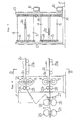
- Figs. 1 to 4 illustrate a general structure and functions of a cut-off section provided in a corrugate machine according to one preferred embodiment of the present invention.
- the illustrated cut-off section is similar to the already described apparatus in the prior art with respect to the point that it cuts a corrugated cardboard sheet 1 continuously fed from the preceding stage nearly at right angles to the traveling direction of the sheet 1.
- a characteristic feature of the present invention resides in that the cutting apparatus has such construction that when two kinds of product sheets 2a and 2b having different lengths are to be produced from a traveling single corrugated cardboard sheet 1, it can be achieved without branching the traveling route of the sheet into upper and lower routes as is the case with the heretofore known apparatus.
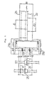
- a rotary type drum shear 3 is provided with two sets of drum shears 3a and 3b severed nearly at the center as illustrated in Fig. 4, and the respective drum shears can be driven individually.
- the respective ones of the two sets of rotary type drum shears 3a and 3b comprise pairs of upper and lower hollow cylinders 4a, 5a and 4b, 5b, onto their circumferential surfaces are fixedly secured linear or spiral knives 6a, 7a and 6b, 7b, respectively, nearly in parallel to their axial directions, the respective knives 6a, 7a and 6b, 7b are engaged with each other by rotating the respective upper and lower hollow cylinders 4a, 5a and 4b, 5b in the opposite directions to each other, and thereby the corrugated cardboard sheet 1 can be sheared.
- the respective hollow knife cylinders 4a, 5a and 4b, 5b having the knives 6a, 7a and 6b, 7b fixedly secured thereto, are rotatably supported from two upper and lower shafts 9 and 10 via bearings 8, 8, 8, 8 interposed at the both end portions of the respective cylinders, and the respective shafts 9 and 10 are supported via taper sleeves 11 from frames 12 and 13 provided uprightly at the opposite ends of the width of the apparatus.
- gears 14a, 14b and 15a, 15b are respectively mounted to the respective frame side end portions of the above-mentioned left and right knife cylinders 4a, 4b and 5a, 5b, and the respective upper and lower gears 14a, 15a and 14b, 15b are meshed with each other.
- the lower gears 15a and 15b are respectively meshed with drive gears 19a, 19b fixedly secured to the tip ends of shafts 18 which are connected via couplings 17 to shafts of separate prime moves 16a, 16b.
- the above-mentioned gears 14a and 15a, and the gears 14b and 15b respectively have equal numbers of teeth.
- the rotary type drum shear 3 constructed in the above-described manner is installed on a base 21 which is movable via traversing means such as traveling wheels 20 or the like, so that it can move in the widthwise direction of the traveling corrugated cardboard sheet 1 to make setting of a slitting position.
- traversing means such as traveling wheels 20 or the like
- scoring rolls 25 and slitter knives 26 similar to those in the heretofore known apparatus shown in Figs. 5 to 8 are provided on the upstream side in the sheet traveling direction of the drum shear 3.
- Figs. 1 to 4 illustrate the case of double size production where two kinds of product sheets 2a, 2b having different lengths are produced from a single corrugated cardboard sheet 1.
- a continuously traveling corrugated cardboard sheet 1 has been subjected to scoring work (K) in a slitter-scorer, it is severed into two slitted sheets.
- the severed sheet on one side has its traveling speed detected by means of a measuring roller 22a, and it is cut into the lengths l2 by actuation of the rotary type drum shear 3a as controlled by feedback of the detection signal.
- the severed sheet on the other side has its traveling speed detected by a measuring roller 22b disposed in juxtaposition to the above-mentioned measuring roller 22a, and it is cut into the lengths l1 by actuation of the rotary type drum shear 3b on the other side as controlled by feedback of the detection signal.
- the product sheets 2a and 2b cut in the above-described manner are transported to the subsequent stage at the downstream via transport conveyors 23a and 23b.
- the cutting apparatus Since the cutting apparatus according to the present invention is constructed and operates in the above-described manner, if the position in the sheet widthwise direction of the rotary type drum shear 3 is preset so as to be adapted to the position of the slitting slot S on the sheet, then many kinds of different product sheets 2a, 2b can be produced simultaneously. In addition, as a matter of course, if the operation timings of the two sets of drum shears 3a and 3b are adjusted, it is also possible to achieve cutting over the entire width of the corrugated cardboard sheets.
- the rotary drum type cutting apparatus is equivalent in structure to two, left and right sets of rotary drum type cutting apparatus having a pair of upper and lower shafts used in common and placed in juxtaposition to each other, if the cutting apparatus mainbody is disposed at the slitting slot position on the traveling sheet-like article and the respective ones of two pairs of upper and lower drums are operated independently in correspondence to the respective sheet traveling speeds and the product lengths, then two kinds of products can be produced simultaneously in the same sheet traveling route.
- the present invention affords the following advantages:
Landscapes
- Life Sciences & Earth Sciences (AREA)
- Forests & Forestry (AREA)
- Engineering & Computer Science (AREA)
- Mechanical Engineering (AREA)
- Making Paper Articles (AREA)
- Gripping Jigs, Holding Jigs, And Positioning Jigs (AREA)
- Shearing Machines (AREA)
- Unwinding Webs (AREA)
Applications Claiming Priority (2)
| Application Number | Priority Date | Filing Date | Title |
|---|---|---|---|
| JP1293117A JP2706332B2 (ja) | 1989-11-10 | 1989-11-10 | 回転ドラム式切断装置 |
| JP293117/89 | 1989-11-10 |
Publications (3)
| Publication Number | Publication Date |
|---|---|
| EP0427244A2 true EP0427244A2 (de) | 1991-05-15 |
| EP0427244A3 EP0427244A3 (en) | 1991-11-06 |
| EP0427244B1 EP0427244B1 (de) | 1993-03-10 |
Family
ID=17790650
Family Applications (1)
| Application Number | Title | Priority Date | Filing Date |
|---|---|---|---|
| EP90121335A Expired - Lifetime EP0427244B1 (de) | 1989-11-10 | 1990-11-07 | Schervorrichtung mit rotierendem Messer |
Country Status (5)
| Country | Link |
|---|---|
| EP (1) | EP0427244B1 (de) |
| JP (1) | JP2706332B2 (de) |
| AU (1) | AU6582590A (de) |
| DE (1) | DE69001061T2 (de) |
| ES (1) | ES2038476T3 (de) |
Cited By (2)
| Publication number | Priority date | Publication date | Assignee | Title |
|---|---|---|---|---|
| EP0627285A3 (de) * | 1991-02-12 | 1995-09-06 | Cremona Angelo & Figlio | Vorrichtung zum Querschneiden von Holzfurnier. |
| EP2388114A1 (de) | 2010-05-17 | 2011-11-23 | Hunkeler AG | Vorrichtung zum Querperforieren oder Querschneiden von bewegten Materialbahnen |
Family Cites Families (2)
| Publication number | Priority date | Publication date | Assignee | Title |
|---|---|---|---|---|
| US3107589A (en) * | 1961-01-11 | 1963-10-22 | Samuel M Langston Co | Board feed squaring device for rotary cutoff machines |
| US4493235A (en) * | 1983-04-15 | 1985-01-15 | Merrill David Martin | Axially adjustable helical cutting blades for rotary web shearing machine |
-
1989
- 1989-11-10 JP JP1293117A patent/JP2706332B2/ja not_active Expired - Fee Related
-
1990
- 1990-11-05 AU AU65825/90A patent/AU6582590A/en not_active Abandoned
- 1990-11-07 DE DE9090121335T patent/DE69001061T2/de not_active Expired - Fee Related
- 1990-11-07 ES ES199090121335T patent/ES2038476T3/es not_active Expired - Lifetime
- 1990-11-07 EP EP90121335A patent/EP0427244B1/de not_active Expired - Lifetime
Cited By (3)
| Publication number | Priority date | Publication date | Assignee | Title |
|---|---|---|---|---|
| EP0627285A3 (de) * | 1991-02-12 | 1995-09-06 | Cremona Angelo & Figlio | Vorrichtung zum Querschneiden von Holzfurnier. |
| EP2388114A1 (de) | 2010-05-17 | 2011-11-23 | Hunkeler AG | Vorrichtung zum Querperforieren oder Querschneiden von bewegten Materialbahnen |
| CH703163A1 (de) * | 2010-05-17 | 2011-11-30 | Hunkeler Ag | Vorrichtung zum Querperforieren oder Querschneiden von bewegten Materialbahnen. |
Also Published As
| Publication number | Publication date |
|---|---|
| JP2706332B2 (ja) | 1998-01-28 |
| AU6582590A (en) | 1991-05-16 |
| ES2038476T3 (es) | 1993-07-16 |
| JPH03154783A (ja) | 1991-07-02 |
| DE69001061D1 (de) | 1993-04-15 |
| EP0427244B1 (de) | 1993-03-10 |
| DE69001061T2 (de) | 1993-06-17 |
| EP0427244A3 (en) | 1991-11-06 |
Similar Documents
| Publication | Publication Date | Title |
|---|---|---|
| US5230268A (en) | Device for cross cutting and/or perforating of a web | |
| US5152205A (en) | Rotary shear | |
| EP0534177B1 (de) | Rotierende Schneidvorrichtung | |
| US6139003A (en) | Process and device for producing multi-layered newspaper products with a tabloid section | |
| JPH06210772A (ja) | コルゲートマシンのオーダーチェンジシステム | |
| DE69532531T2 (de) | Gerät zum wenden und zum hintereinander angeordnet bereitstellen von bogenmaterial und entsprechendes verfahren | |
| JPS6186351A (ja) | 包装機用原反リール切換方法およびその装置 | |
| US6019714A (en) | Folding apparatus with signature divider | |
| US4184392A (en) | Web cutting machines | |
| US6949062B2 (en) | Apparatus for adjusting pull rollers and/or cutting knives in folders | |
| EP0088314A1 (de) | Rollenträger mit Schneidevorrichtung | |
| US5953971A (en) | Dual web singulating cutter | |
| AU620758B2 (en) | Slitterscorer | |
| US4491310A (en) | Adjustable folding apparatus | |
| US4190243A (en) | Folder assembly for book folding | |
| DE69219381T2 (de) | Bogenschneidmaschine für geschältes Holzfurnier | |
| EP0345418A3 (de) | Bogenausgabesystem | |
| DE69919530T2 (de) | Vorrichtung zum vereinzeln von gegenständen | |
| US4109902A (en) | Apparatus for the continuous zigzag folding of a material web | |
| EP0427244B1 (de) | Schervorrichtung mit rotierendem Messer | |
| EP0763492A2 (de) | Papierschneidegerät in einer Papierfalzvorrichtung für eine Formulardruckmaschine und Papierschneidverfahren | |
| EP0890538B1 (de) | Rollenschneider | |
| JPH0569390A (ja) | 回転ドラム式切断装置 | |
| EP0752299A1 (de) | Rotationsschlitzvorrichtung | |
| US4416652A (en) | Unit for scoring webs of paper in the lengthways direction |
Legal Events
| Date | Code | Title | Description |
|---|---|---|---|
| PUAI | Public reference made under article 153(3) epc to a published international application that has entered the european phase |
Free format text: ORIGINAL CODE: 0009012 |
|
| 17P | Request for examination filed |
Effective date: 19901204 |
|
| AK | Designated contracting states |
Kind code of ref document: A2 Designated state(s): CH DE ES FR GB IT LI |
|
| PUAL | Search report despatched |
Free format text: ORIGINAL CODE: 0009013 |
|
| AK | Designated contracting states |
Kind code of ref document: A3 Designated state(s): CH DE ES FR GB IT LI |
|
| 17Q | First examination report despatched |
Effective date: 19920803 |
|
| GRAA | (expected) grant |
Free format text: ORIGINAL CODE: 0009210 |
|
| AK | Designated contracting states |
Kind code of ref document: B1 Designated state(s): CH DE ES FR GB IT LI |
|
| ET | Fr: translation filed | ||
| REF | Corresponds to: |
Ref document number: 69001061 Country of ref document: DE Date of ref document: 19930415 |
|
| ITF | It: translation for a ep patent filed | ||
| REG | Reference to a national code |
Ref country code: ES Ref legal event code: FG2A Ref document number: 2038476 Country of ref document: ES Kind code of ref document: T3 |
|
| PLBE | No opposition filed within time limit |
Free format text: ORIGINAL CODE: 0009261 |
|
| STAA | Information on the status of an ep patent application or granted ep patent |
Free format text: STATUS: NO OPPOSITION FILED WITHIN TIME LIMIT |
|
| 26N | No opposition filed | ||
| REG | Reference to a national code |
Ref country code: GB Ref legal event code: IF02 |
|
| PGFP | Annual fee paid to national office [announced via postgrant information from national office to epo] |
Ref country code: GB Payment date: 20021106 Year of fee payment: 13 |
|
| PGFP | Annual fee paid to national office [announced via postgrant information from national office to epo] |
Ref country code: FR Payment date: 20021108 Year of fee payment: 13 |
|
| PGFP | Annual fee paid to national office [announced via postgrant information from national office to epo] |
Ref country code: CH Payment date: 20021115 Year of fee payment: 13 |
|
| PG25 | Lapsed in a contracting state [announced via postgrant information from national office to epo] |
Ref country code: GB Free format text: LAPSE BECAUSE OF NON-PAYMENT OF DUE FEES Effective date: 20031107 |
|
| PG25 | Lapsed in a contracting state [announced via postgrant information from national office to epo] |
Ref country code: CH Free format text: LAPSE BECAUSE OF NON-PAYMENT OF DUE FEES Effective date: 20031130 Ref country code: LI Free format text: LAPSE BECAUSE OF NON-PAYMENT OF DUE FEES Effective date: 20031130 |
|
| GBPC | Gb: european patent ceased through non-payment of renewal fee |
Effective date: 20031107 |
|
| REG | Reference to a national code |
Ref country code: CH Ref legal event code: PL |
|
| PG25 | Lapsed in a contracting state [announced via postgrant information from national office to epo] |
Ref country code: FR Free format text: LAPSE BECAUSE OF NON-PAYMENT OF DUE FEES Effective date: 20040730 |
|
| REG | Reference to a national code |
Ref country code: FR Ref legal event code: ST |
|
| PGFP | Annual fee paid to national office [announced via postgrant information from national office to epo] |
Ref country code: DE Payment date: 20061102 Year of fee payment: 17 |
|
| PG25 | Lapsed in a contracting state [announced via postgrant information from national office to epo] |
Ref country code: DE Free format text: LAPSE BECAUSE OF NON-PAYMENT OF DUE FEES Effective date: 20080603 |
|
| PGFP | Annual fee paid to national office [announced via postgrant information from national office to epo] |
Ref country code: ES Payment date: 20081127 Year of fee payment: 19 |
|
| PGFP | Annual fee paid to national office [announced via postgrant information from national office to epo] |
Ref country code: IT Payment date: 20081126 Year of fee payment: 19 |
|
| PG25 | Lapsed in a contracting state [announced via postgrant information from national office to epo] |
Ref country code: IT Free format text: LAPSE BECAUSE OF NON-PAYMENT OF DUE FEES Effective date: 20091107 |
|
| REG | Reference to a national code |
Ref country code: ES Ref legal event code: FD2A Effective date: 20110408 |
|
| PG25 | Lapsed in a contracting state [announced via postgrant information from national office to epo] |
Ref country code: ES Free format text: LAPSE BECAUSE OF NON-PAYMENT OF DUE FEES Effective date: 20110328 |
|
| PG25 | Lapsed in a contracting state [announced via postgrant information from national office to epo] |
Ref country code: ES Free format text: LAPSE BECAUSE OF NON-PAYMENT OF DUE FEES Effective date: 20091108 |