EP0432986B1 - Imprimante avec dispositif pour éliminer le coincement du papier - Google Patents
Imprimante avec dispositif pour éliminer le coincement du papier Download PDFInfo
- Publication number
- EP0432986B1 EP0432986B1 EP90313376A EP90313376A EP0432986B1 EP 0432986 B1 EP0432986 B1 EP 0432986B1 EP 90313376 A EP90313376 A EP 90313376A EP 90313376 A EP90313376 A EP 90313376A EP 0432986 B1 EP0432986 B1 EP 0432986B1
- Authority
- EP
- European Patent Office
- Prior art keywords
- housing portion
- printer
- platen
- top portion
- latch
- Prior art date
- Legal status (The legal status is an assumption and is not a legal conclusion. Google has not performed a legal analysis and makes no representation as to the accuracy of the status listed.)
- Expired - Lifetime
Links
- 230000008901 benefit Effects 0.000 description 5
- 210000003811 finger Anatomy 0.000 description 3
- 238000001816 cooling Methods 0.000 description 2
- 210000004935 right thumb Anatomy 0.000 description 2
- 238000010586 diagram Methods 0.000 description 1
- 230000005484 gravity Effects 0.000 description 1
- 210000004936 left thumb Anatomy 0.000 description 1
- 238000012423 maintenance Methods 0.000 description 1
- 238000000034 method Methods 0.000 description 1
- 210000003813 thumb Anatomy 0.000 description 1
Images



Classifications
-
- B—PERFORMING OPERATIONS; TRANSPORTING
- B41—PRINTING; LINING MACHINES; TYPEWRITERS; STAMPS
- B41J—TYPEWRITERS; SELECTIVE PRINTING MECHANISMS, i.e. MECHANISMS PRINTING OTHERWISE THAN FROM A FORME; CORRECTION OF TYPOGRAPHICAL ERRORS
- B41J11/00—Devices or arrangements of selective printing mechanisms, e.g. ink-jet printers or thermal printers, for supporting or handling copy material in sheet or web form
- B41J11/48—Apparatus for condensed record, tally strip, or like work using two or more papers, or sets of papers, e.g. devices for switching over from handling of copy material in sheet form to handling of copy material in continuous form and vice versa or point-of-sale printers comprising means for printing on continuous copy material, e.g. journal for tills, and on single sheets, e.g. cheques or receipts
- B41J11/54—Apparatus for condensed record, tally strip, or like work using two or more papers, or sets of papers, e.g. devices for switching over from handling of copy material in sheet form to handling of copy material in continuous form and vice versa or point-of-sale printers comprising means for printing on continuous copy material, e.g. journal for tills, and on single sheets, e.g. cheques or receipts in which one paper or set is fed towards printing position from the front of the apparatus
-
- B—PERFORMING OPERATIONS; TRANSPORTING
- B41—PRINTING; LINING MACHINES; TYPEWRITERS; STAMPS
- B41J—TYPEWRITERS; SELECTIVE PRINTING MECHANISMS, i.e. MECHANISMS PRINTING OTHERWISE THAN FROM A FORME; CORRECTION OF TYPOGRAPHICAL ERRORS
- B41J29/00—Details of, or accessories for, typewriters or selective printing mechanisms not otherwise provided for
- B41J29/02—Framework
Definitions
- the present invention relates to a printer.
- a recent trend making business machines more versatile relates to making them conducive to being used by an operator when the operator is standing or sitting at the machine.
- Some prior art business machines have too high a profile for use in such sit/stand operations.
- EP-A-0271090 AND EP-A-0281109 each disclose a printer apparatus which includes a housing having upper and lower portions, the upper portion being pivotable relative to the lower portion so as to provide access into the printer.
- the upper portion is pivoted by way of two levers.
- the access available is disadvantageously restricted in each case and so only limited maintenance operations can be carried out.
- An object of the present invention is to provide a compact printer which facilitates the easy removal of a document which has become jammed within the printer.
- a printer having a first housing portion and a second housing portion which is positioned above said first housing portion and which is pivotably mounted with respect to said first housing portion so as to be movable between a lowered position and a raised position, platen means mounted in said first housing portion, first and second feed roller means which are respectively mounted in said first and second housing portions and which cooperate with each other for the purpose of feeding a document to be printed to said platen means when said second housing portion is in said lowered position, characterized by a printer head and ink ribbon means which are mounted in said second housing portion and which cooperate with said platen for the purpose of a print operation when said second housing portion is in said lowered position, and latch means for selectively latching said second housing portion in said lowered position or said raised position, and in that said second housing portion is provided with a panel movable between open and closed positions, said panel when in said open position, permitting operation of said latch means to permit said second housing portion to be moved to said raised position.
- the present invention benefits from the advantages of providing easy access to the printer for removal of a jammed document, and easy for access changing the ink ribbon.
- the printer 10 includes a bottom portion 12 and a top portion 14 which are shown in the normal operating or assembled position.
- the top portion 14 of the printer 10 also includes a panel 16 which includes a keyboard 18 and a display 20.
- the printer 10 has the associated print station 22 (Fig. 2) and a document path 24 (Fig. 1) leading to the print station 22 lying between the bottom portion 12 and the top portion 14 of the printer cabinet 26.
- the document path 24 has a guide rail 28 which provides a means for aligning a document as it is moved towards the print station 22.
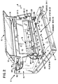
- a pivot 30 is provided for the bottom and top portions 12 and 14 of the cabinet 26 so as to enable the top portion 14 to be pivoted from the assembled position shown in Fig. 1 to the opened position shown in Fig. 2. In the opened position, the print station 22 is exposed, permitting a jammed document (not shown) which may be stuck at the print station 22 to be removed.
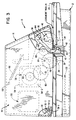
- the pivot 30 is conventional, and it includes a pair of upright portions 30-1, extending upwardly from the bottom portion 12, with only one upright portion 30-1 shown in Fig. 3.
- the top portion 14 has a rod 30-2 mounted therein, with the rod 30-2 being supported in the pair of upright portions 30-1.
- Each of the upright portions 30-1 also has a slotted circular recess 30-3 therein to enable the rod 30-2 to be mounted therein as is conventionally done.
- the bottom portion 12 is made as small as it can be so as to make the printer 10 adaptable for sit/stand operations as previously discussed.
- the overall height of the bottom portion 12 is small compared to the overall height of the top portion 14, and the absolute overall height of the bottom portion 12 is less than two inches (5.08 cm) in the embodiment described. Having the bottom portion 12 small as described facilitates using the printer 10 when an operator sits down to use the printer.
- the bottom portion 12 houses a first bank of pinch rollers 32 which are rotatably mounted on a rod 34 (Fig. 3) and also houses a second bank of pinch rollers 36 which are rotatably mounted on a rod 38.
- the first bank of pinch rollers 32 is mounted on one side of the print station 22 as shown in Fig. 2, and the second bank of pinch rollers 36 is mounted on the other side of the print station 22.
- a rectangularly shaped platen 40 is mounted between the first and second banks of pinch rollers 32 and 36 as shown best in Fig. 2.
- the first and second banks of pinch rollers 32 and 36 and the platen 40 are conventionally biased upwardly as shown in Fig. 3 by suitable springs (not shown).
- the platen 40 is mounted in a generally "U"-shaped member 42 (Fig. 3) which extends along the length of the platen 40.
- the first and second banks of pinch rollers 32 and 36, just described, are part of a conventional document transport 44, shown schematically in Fig. 4.
- the printer 10 is provided with drive rollers (46, 48) associated with the document transport 44 in the top portion 14 of the printer 10.
- the drive rollers of the document transport 44 are in operative relationship with the first and second banks of pinch rollers 36 and 38.
- the drive rollers of the document transport 44 include a first bank of drive rollers 46 and a second bank of drive rollers 48 which are aligned with the first and second banks of pinch rollers 32 and 36, respectively, as shown in Fig. 3.
- the first bank of drive rollers 46 is mounted on a shaft 50
- the second bank of drive rollers 48 is mounted on a shaft 52.
- the shafts 50 and 52 are mounted in the side frames 54 and 56 which are shown in diagrammatic form in Fig. 2.
- the document transport 44 also includes a bi-directional motor 58 (Fig. 3) which is used to power the first and second banks of drive rollers 46 and 48 to drive a document towards and away from the print station 22.
- the motor 58 has an output gear 60 which drives or rotates an intermediate gear 62, which in turn, rotates a gear 64 which is fixed to the shaft 52 to rotate it and the drive rollers 48 mounted thereon.
- a drive gear 66 is similarly fixed to the shaft 50 to rotate it and the first bank of drive rollers 46 fixed to the shaft 50.
- a gear 68 in mesh with both the gears 64 and 66, is used to rotate gear 66 in the same direction as gear 64 is rotated to drive or rotate the first and second banks of drive rollers 46 and 48 in the same direction.
- the gear 68 is mounted on a rod 70, and the intermediate gear 62 is also mounted on a rod 72.
- the rods 70 and 72 are mounted between the side frames 54 and 56.
- the flange 58-1 of the motor 58 is secured to the side frame 54 by suitable fasteners 58-2. Because the document transport means 44 just described is conventional, it need not be described in any further detail.
- the printing mechanism of the printer is located in the top portion 14.
- This printing mechanism includes a print head 74, an indexing mechanism 76 (Fig. 4) to move the print head 74 along the length of the platen 40, and a motor 78 to power the indexing mechanism 76.
- the indexing mechanism 76 is conventional and includes a carriage 80 and traversing screw (not shown) which are used to move the print head 74 along the length of the platen 40 Because this aspect is conventional, it need not be described in any further detail.
- the print head also includes a ribbon bracket 82 which attaches to the lower end (as viewed in Fig. 2) of the print head 74 and guides a ribbon 84 from the ribbon cassette 86 around the printing end of the printer 74.
- a ribbon bracket 82 attaches to the lower end (as viewed in Fig. 2) of the print head 74 and guides a ribbon 84 from the ribbon cassette 86 around the printing end of the printer 74.
- the platen 40 associated with the printer head 74 is located in the bottom portion 12 as previously described.
- the platen 40 has a ramp portion 90 on the right side of the platen as viewed in Fig. 2.
- a roller (not shown) on the print head 74 engages the ramp portion 90 when the print head 74 is moved to a home position or the right side of the platen 40 as viewed in Fig. 2.
- the roller rides up the ramp portion 90 to lower the platen 40 below the surface 24-1 of the document path 24 to enable a document to be moved to the print station 22.
- the platen 40 is a "free floating" variety so that when the print head 74 moves off the ramp portion 90, platen 40 moves towards the print head 74 to accommodate different thicknesses of documents or media.
- a moveable panel 16 is provided for the top portion 14. This feature also facilitates clearing a document which may be jammed at the print station 22, and it also facilitates changing a ribbon cassette 86, especially when the top portion 14 is in the position shown in Fig. 2. When in this position, the bracket 82 on the end of the print head 74 is spaced from the print station 22, permitting easy access to the ribbon 84.
- the moveable panel 16 has generally "L"-shaped arms 92 and 94 extending from the inside of the moveable cover 16 as shown best in Fig. 2.
- Each arm, like 92 is pivotally mounted on a stud 96 which extends from the interior of the top portion 14 to enable the moveable panel 16 to be pivoted from the closed position shown in Fig. 1 to the opened position shown in Fig. 2.
- Each arm, like 92 has a projection 98 extending therefrom to which one end of a tension spring 100 is secured, with the remaining end of the spring 100 being secured to a post 102 depending from the top portion 14.
- arms 92 and 94 provide a conventional "over-the-centre" linkage to enable the moveable cover to be resiliently held in the open position shown in Fig. 2 and to be resiliently held in the closed position shown in Fig. 1.
- a latching means is provided for detachably latching the bottom and top portions 12 and 14 in the assembled relationship shown in Fig. 1 and the open position shown in Fig. 2.
- there is a first set of latches for detachably holding the top portion 14 and the bottom portion 12 in the assembled position shown in Fig. 1.
- the latches 104 and 106 are mirror images of each other, so consequently, only a description of latch 104 need be given.
- the latch member 104 is generally "L"-shaped in outline as shown in Fig. 5.
- the latch member 104 is pivotally joined to side frame 54 by a suitable means, shown as a pin 108, and it has a shoulder 110 which abuts under a stop 112 located in the bottom portion 12.
- the lower end of the latch member 104 passes through an opening 114 in the bottom portion 12, and this member is kept in the position shown in Fig. 5 by a resilient pad 116 (secured to the side frame 54) which resiliently biases the member in a counter-clockwise direction as viewed in Fig. 5.
- the latch member 106 shown in Fig. 7 is a mirror image of the latch member 104 just described.
- the latch member 106 is pivotally mounted in the side frame 56 (represented by a pin 118) and is resiliently biased in a clockwise direction (as viewed in Fig. 7) by a resilient pad 120 which is secured to the side frame 56.
- the lower end 106-1 of the latch member 106 engages a stop 122 in the bottom portion 12, and the upper end 106-2 engages the resilient pad 120.
- an operator moves the panel 16 from the position shown in Fig. 1 to the opened position shown in Fig. 2, exposing the interior of the top portion 14.
- the operator places his/her left thumb under the top portion 14 in the area shown by arrow 124 in Fig. 2, and, correspondingly, places the right thumb under the top portion 14 in the area shown by arrow 126.
- the operator's thumb nails would be contacting the bottom portion 12 at this time.
- the operator places the left index finger on the upper end 104-1 (Fig. 6) of the latch lever 104 and compresses the resilient member 116 to thereby rotate the latch lever 104 in a clockwise direction as viewed in Fig. 5.
- the second latch means includes a latch 124 (Figs. 7 and 8) having its lower end 124-1 pivotally joined to a pivot member 126 upstanding from the bottom portion 12.
- the latch member 124 has an elongated slot 124-2 therein to receive a stud 128 which extends from the side frame 56.
- the elongated slot 124-2 has a radius of curvature whose origin lies at the centre of the pivot 30 (Fig. 3)
- the stud 128 rides up the slot 124-2 (as viewed in Fig.
- the upper portion of the latch 124 has a handle 124-5 to facilitate lowering the top portion 14 of the printer 10. To do this, an operator simply raises the top portion 14 slightly, and then pulls the handle 124-5 of the latch 124 towards the front of the printer 10 (a counter-clockwise direction as viewed in Fig. 7) to permit the stud 128 to pass over the point 124-3. Thereafter, the stud 128 rides down the slot 124-2, as viewed in Fig. 7, until the latch members 104 and 106 become latched to the stops 112 and 122 as previously described.
- the handles 104-1, 106-2, and 124-5 of the various latches just described are colored green according to color coding standards to make such handles visible to an operator when panel is moved to the position shown in Fig. 2. The color green indicates operator controlled elements.
- Locating the power supply 130 here meant that normal convection cooling techniques could be used to cool the supply 130 instead of having to use a cooling fan when a power supply is located in the bottom portion, like 12, of a printer.
- the printer 10 has a control board 132, including a microprocessor (MP) 134 for controlling the operations of the printer 10 as is conventionally done.
- the control board 132 is located in the bottom portion 12 as seen in Fig. 3 which facilitates having a low profile for the printer 10.
- the various elements of the printer 10 are conventionally interconnected as shown schematically in Fig. 4.
- Another advantage of the printer 10 is that its design enables a redesign of the bottom portion 12 to add another printer, like a journal printer, for example, without having to redesign the top portion 14 where most of the elements of the printer reside.
- Another advantage is that the printer benefits from compactness by virtue of the low profile nature of the bottom portion (12) compared with that of the top portion (14), and is suitable for operation by an operator sitting or standing.
Landscapes
- Accessory Devices And Overall Control Thereof (AREA)
- Handling Of Cut Paper (AREA)
Claims (5)
- Une imprimante ayant une première partie de boîtier (12) et une deuxième partie de boîtier (14) qui est positionnée au-dessus de ladite première partie de boîtier (12) et qui est montée de façon à pouvoir pivoter par rapport à ladite première partie de boîtier de façon à pouvoir être déplacée entre une position abaissée et une position relevée, un moyen plateau (40) monté dans ladite première partie de boîtier, des premier et deuxième moyens rouleaux d'alimentation (32, 36; 46, 48) qui sont respectivement montés dans lesdites première et deuxième parties de boîtier et qui coopèrent l'un avec l'autre aux fins de l'alimentation d'un document à imprimer audit moyen plateau (40) lorsque ladite deuxième partie de boîtier (14) est dans ladite position abaissée, caractérisée par une tête d'imprimante (74) et un moyen ruban encreur (86) qui sont montés dans ladite deuxième partie de boîtier et qui coopèrent avec ledit plateau (40) aux fins d'une opération d'impression lorsque ladite deuxième partie de boîtier est dans ladite position abaissée, et un moyen verrou (104, 106, 124) pour verrouiller sélectivement ladite deuxième partie de boîtier (14) dans ladite position abaissée ou dans ladite position relevée, et en ce que ladite deuxième partie de boîtier (14) est dotée d'un panneau (16) pouvant être déplacé entre des positions ouverte et fermée, ledit panneau, lorsqu'il est dans ladite position ouverte, permettant la manoeuvre dudit moyen verrou (104, 106) pour permettre de faire passer ladite deuxième partie de boîtier à ladite position relevée.
- Une imprimante conformément à la revendication 1, caractérisée en ce que ladite deuxième partie de boîtier (14) loge un moteur électrique (58) et un moyen d'entraînement (60, 62, 64, 66, 68) pour entraîner ledit deuxième moyen rouleau d'alimentation (46, 48).
- Une imprimante conformément à la revendication 2, caractérisée en ce qu'une alimentation (130) est logée dans ladite deuxième partie de boîtier (14).
- Une imprimante conformément à l'une quelconque des revendications précédentes, caractérisée en ce que ledit panneau (16) supporte un clavier (18) et un moyen d'affichage (20).
- Une imprimante conformément à l'une quelconque des revendications précédentes, caractérisée en ce que ladite première partie de boîtier (12) a une hauteur hors tout qui est petite par rapport à la hauteur hors tout de ladite deuxième partie de boîtier (14).
Applications Claiming Priority (2)
| Application Number | Priority Date | Filing Date | Title |
|---|---|---|---|
| US07/448,389 US5017033A (en) | 1989-12-11 | 1989-12-11 | Method of producing a printer which facilitates clearing a jammed document |
| US448389 | 1989-12-11 |
Publications (2)
| Publication Number | Publication Date |
|---|---|
| EP0432986A1 EP0432986A1 (fr) | 1991-06-19 |
| EP0432986B1 true EP0432986B1 (fr) | 1994-04-27 |
Family
ID=23780125
Family Applications (1)
| Application Number | Title | Priority Date | Filing Date |
|---|---|---|---|
| EP90313376A Expired - Lifetime EP0432986B1 (fr) | 1989-12-11 | 1990-12-10 | Imprimante avec dispositif pour éliminer le coincement du papier |
Country Status (5)
| Country | Link |
|---|---|
| US (1) | US5017033A (fr) |
| EP (1) | EP0432986B1 (fr) |
| JP (1) | JP2811604B2 (fr) |
| CA (1) | CA2028452C (fr) |
| DE (1) | DE69008497T2 (fr) |
Cited By (1)
| Publication number | Priority date | Publication date | Assignee | Title |
|---|---|---|---|---|
| US7343220B2 (en) | 1998-04-29 | 2008-03-11 | Automated Merchandising Systems Inc. | Optical vend-sensing system for control of vending machine |
Families Citing this family (23)
| Publication number | Priority date | Publication date | Assignee | Title |
|---|---|---|---|---|
| USD324234S (en) | 1989-04-27 | 1992-02-25 | Seiko Epson Corporation | Printer for electronic computer |
| DE4008541C1 (fr) * | 1990-03-16 | 1991-11-21 | Siemens Nixdorf Informationssysteme Ag, 4790 Paderborn, De | |
| IT1239396B (it) * | 1990-03-20 | 1993-10-20 | Printax | Apparecchiatura stampante portatile |
| GB2247647B (en) * | 1990-08-20 | 1995-01-18 | Seikosha Kk | Dot printer |
| US5187374A (en) * | 1991-03-21 | 1993-02-16 | Ncr Corporation | Optical paper sensing method and apparatus having light source and detector moveable in pivotal relation |
| JPH06122247A (ja) * | 1992-08-26 | 1994-05-06 | Brother Ind Ltd | プリンタ |
| USD354303S (en) | 1993-06-17 | 1995-01-10 | Taurus Impressions, Inc. | Hot debossing stamper machine |
| JP2991596B2 (ja) * | 1993-09-03 | 1999-12-20 | キヤノン株式会社 | 記録装置 |
| SG73372A1 (en) * | 1993-09-08 | 2000-06-20 | Hitachi Ltd | An ink jet printing apparatus and a printing head for such an ink jet printing apparatus |
| JP2863978B2 (ja) * | 1993-09-14 | 1999-03-03 | 松下電器産業株式会社 | 電子機器装置 |
| KR960029111A (ko) * | 1995-01-13 | 1996-08-17 | 스즈키 아끼오 | 프린터 |
| US6588869B1 (en) * | 1998-11-05 | 2003-07-08 | Gateway, Inc. | Front accessible, stackable, printer/scanner/fax |
| US6132122A (en) * | 1999-08-23 | 2000-10-17 | Hewlett-Packard Company | Low profile architecture for internet appliance printing |
| US6340256B1 (en) * | 2000-01-05 | 2002-01-22 | Hewlett-Packard Company | Media channel and method of clearing media jams |
| US6290409B1 (en) * | 2000-01-05 | 2001-09-18 | Hewlett-Packard Company | Media observation frame and method of using same |
| US6287032B1 (en) | 2000-01-05 | 2001-09-11 | Hewlett-Packard Company | Media tray supporter and method of using same |
| US6276852B1 (en) * | 2000-01-05 | 2001-08-21 | Hewlett-Packard Company | Low profile printer with open bottom paper path |
| US6296407B1 (en) * | 2000-01-05 | 2001-10-02 | Hewlett-Packard Company | Stackable low profile printer with an input and output media telescoping tray cassette |
| US20050146591A1 (en) * | 2004-01-07 | 2005-07-07 | Matsushita Electric Industrial Co., Ltd. | Recording apparatus |
| JP4556890B2 (ja) * | 2005-05-16 | 2010-10-06 | パナソニック株式会社 | 画像形成装置 |
| JP1591417S (fr) * | 2017-04-21 | 2017-11-20 | ||
| JP1593606S (fr) * | 2017-07-31 | 2018-11-19 | ||
| JP1597537S (fr) * | 2017-09-19 | 2018-02-13 |
Citations (1)
| Publication number | Priority date | Publication date | Assignee | Title |
|---|---|---|---|---|
| EP0281109A1 (fr) * | 1987-03-03 | 1988-09-07 | Siemens Nixdorf Informationssysteme Aktiengesellschaft | Appareil à écrire comprenant un assemblage avec tête d'écriture et un support d'écriture |
Family Cites Families (12)
| Publication number | Priority date | Publication date | Assignee | Title |
|---|---|---|---|---|
| GB2046671B (en) * | 1979-04-10 | 1983-08-03 | Shinshu Seiki Kk | Electronic calculator with printer |
| IT1144422B (it) * | 1981-07-23 | 1986-10-29 | Olivetti & Co Spa | Dispositivo per schermare circuiti elettrici |
| DE3208111C2 (de) * | 1982-03-06 | 1984-05-30 | Kienzle Apparate Gmbh, 7730 Villingen-Schwenningen | Druckeinrichtung in modularer Bauweise |
| US4549825A (en) * | 1983-02-08 | 1985-10-29 | Post Technologies, Inc. | Thermal printer for a low cost electronic mail terminal |
| DE3420981A1 (de) * | 1983-08-31 | 1985-03-14 | Kienzle Apparate Gmbh, 7730 Villingen-Schwenningen | Farbvorrichtung mit kassette fuer einen drucker |
| JPS60192668A (ja) * | 1984-03-14 | 1985-10-01 | Toshiba Corp | 画像形成装置 |
| JPS62164551A (ja) * | 1986-01-17 | 1987-07-21 | Ricoh Co Ltd | ライン熱転写プリンタ |
| US4773772A (en) * | 1986-06-13 | 1988-09-27 | Ncr Corporation | Printing apparatus |
| JPS6337970A (ja) * | 1986-08-01 | 1988-02-18 | Alps Electric Co Ltd | ドツトプリンタ |
| US4795282A (en) * | 1987-10-08 | 1989-01-03 | Ncr Corporation | Paper guide and stop for multi-function printer |
| US4851812A (en) * | 1988-06-07 | 1989-07-25 | Basics Corporation | Portable data system |
| US4827282A (en) * | 1988-09-01 | 1989-05-02 | Eastman Kodak Company | Print head assembly acceleration control method |
-
1989
- 1989-12-11 US US07/448,389 patent/US5017033A/en not_active Expired - Fee Related
-
1990
- 1990-10-24 CA CA002028452A patent/CA2028452C/fr not_active Expired - Fee Related
- 1990-11-27 JP JP2321371A patent/JP2811604B2/ja not_active Expired - Fee Related
- 1990-12-10 DE DE69008497T patent/DE69008497T2/de not_active Expired - Fee Related
- 1990-12-10 EP EP90313376A patent/EP0432986B1/fr not_active Expired - Lifetime
Patent Citations (1)
| Publication number | Priority date | Publication date | Assignee | Title |
|---|---|---|---|---|
| EP0281109A1 (fr) * | 1987-03-03 | 1988-09-07 | Siemens Nixdorf Informationssysteme Aktiengesellschaft | Appareil à écrire comprenant un assemblage avec tête d'écriture et un support d'écriture |
Non-Patent Citations (1)
| Title |
|---|
| PATENT ABSTRACTS OF JAPAN, vol. 6, no. 146, (M-147)(129), August 5, 1982; JP A 57 066 988 * |
Cited By (1)
| Publication number | Priority date | Publication date | Assignee | Title |
|---|---|---|---|---|
| US7343220B2 (en) | 1998-04-29 | 2008-03-11 | Automated Merchandising Systems Inc. | Optical vend-sensing system for control of vending machine |
Also Published As
| Publication number | Publication date |
|---|---|
| DE69008497T2 (de) | 1994-12-15 |
| US5017033A (en) | 1991-05-21 |
| JPH03187770A (ja) | 1991-08-15 |
| CA2028452C (fr) | 1995-12-05 |
| CA2028452A1 (fr) | 1991-06-12 |
| EP0432986A1 (fr) | 1991-06-19 |
| DE69008497D1 (de) | 1994-06-01 |
| JP2811604B2 (ja) | 1998-10-15 |
Similar Documents
| Publication | Publication Date | Title |
|---|---|---|
| EP0432986B1 (fr) | Imprimante avec dispositif pour éliminer le coincement du papier | |
| EP0661163B1 (fr) | Imprimante d'étiquettes et cassette pour bande d'impression et ruban d'encrage utilisés dans cette imprimante | |
| US5393152A (en) | Printing device having opening and shutting mechanism | |
| JPH0442197B2 (fr) | ||
| US5137385A (en) | Printer for use with electronic cash register | |
| EP0063589A1 (fr) | Dispositif de montage d'une roue d'impression pour un ensemble de tete d'impression et de cartouche de ruban. | |
| CA1243894A (fr) | Imprimante matricielle par points | |
| JPH04506188A (ja) | 少なくとも2つの空間的に互いに分離された印刷ステーションを備えた印刷装置 | |
| EP0449237B1 (fr) | Imprimante pour transfert | |
| US5180236A (en) | Transfer printer | |
| US4446790A (en) | Printer with removable print carriage | |
| EP0026890A2 (fr) | Mécanisme d'avance pour feuilles de papier dans une imprimante | |
| US5238314A (en) | Transfer printer with ribbon lock | |
| CA1184866A (fr) | Alimentation d'appareil d'impression | |
| JP3354732B2 (ja) | 原稿読取り確認機構及びそれを組み込んだ原稿読取り装置 | |
| JPH04213531A (ja) | 情報読み取り・書き込み装置 | |
| JP2792154B2 (ja) | プリンタカバー | |
| JPH11106096A (ja) | プリンタ | |
| JP3234680B2 (ja) | プリンタ | |
| JPS62220056A (ja) | 画像形成装置 | |
| JP2551016Y2 (ja) | プリンタ | |
| US8408542B2 (en) | Media processing device | |
| JP2723537B2 (ja) | 金融端末装置 | |
| JPH03294985A (ja) | カード供給装置及びカード製造装置 | |
| JPH0726116Y2 (ja) | 簡易プリンタ |
Legal Events
| Date | Code | Title | Description |
|---|---|---|---|
| PUAI | Public reference made under article 153(3) epc to a published international application that has entered the european phase |
Free format text: ORIGINAL CODE: 0009012 |
|
| AK | Designated contracting states |
Kind code of ref document: A1 Designated state(s): DE FR GB |
|
| 17P | Request for examination filed |
Effective date: 19911115 |
|
| 17Q | First examination report despatched |
Effective date: 19930604 |
|
| RAP1 | Party data changed (applicant data changed or rights of an application transferred) |
Owner name: NCR INTERNATIONAL INC. |
|
| GRAA | (expected) grant |
Free format text: ORIGINAL CODE: 0009210 |
|
| AK | Designated contracting states |
Kind code of ref document: B1 Designated state(s): DE FR GB |
|
| REF | Corresponds to: |
Ref document number: 69008497 Country of ref document: DE Date of ref document: 19940601 |
|
| ET | Fr: translation filed | ||
| PLBE | No opposition filed within time limit |
Free format text: ORIGINAL CODE: 0009261 |
|
| STAA | Information on the status of an ep patent application or granted ep patent |
Free format text: STATUS: NO OPPOSITION FILED WITHIN TIME LIMIT |
|
| 26N | No opposition filed | ||
| PGFP | Annual fee paid to national office [announced via postgrant information from national office to epo] |
Ref country code: FR Payment date: 19991015 Year of fee payment: 10 |
|
| PGFP | Annual fee paid to national office [announced via postgrant information from national office to epo] |
Ref country code: DE Payment date: 19991029 Year of fee payment: 10 |
|
| PGFP | Annual fee paid to national office [announced via postgrant information from national office to epo] |
Ref country code: GB Payment date: 19991203 Year of fee payment: 10 |
|
| PG25 | Lapsed in a contracting state [announced via postgrant information from national office to epo] |
Ref country code: GB Free format text: LAPSE BECAUSE OF NON-PAYMENT OF DUE FEES Effective date: 20001210 |
|
| GBPC | Gb: european patent ceased through non-payment of renewal fee |
Effective date: 20001210 |
|
| PG25 | Lapsed in a contracting state [announced via postgrant information from national office to epo] |
Ref country code: FR Free format text: LAPSE BECAUSE OF NON-PAYMENT OF DUE FEES Effective date: 20010831 |
|
| REG | Reference to a national code |
Ref country code: FR Ref legal event code: ST |
|
| PG25 | Lapsed in a contracting state [announced via postgrant information from national office to epo] |
Ref country code: DE Free format text: LAPSE BECAUSE OF NON-PAYMENT OF DUE FEES Effective date: 20011002 |