EP0433059A2 - Appareil à entraînement à disque avec servo-mécanisme d'alignement - Google Patents
Appareil à entraînement à disque avec servo-mécanisme d'alignement Download PDFInfo
- Publication number
- EP0433059A2 EP0433059A2 EP90313549A EP90313549A EP0433059A2 EP 0433059 A2 EP0433059 A2 EP 0433059A2 EP 90313549 A EP90313549 A EP 90313549A EP 90313549 A EP90313549 A EP 90313549A EP 0433059 A2 EP0433059 A2 EP 0433059A2
- Authority
- EP
- European Patent Office
- Prior art keywords
- data
- servo
- head
- track
- signal
- Prior art date
- Legal status (The legal status is an assumption and is not a legal conclusion. Google has not performed a legal analysis and makes no representation as to the accuracy of the status listed.)
- Granted
Links
Images





Classifications
-
- G—PHYSICS
- G11—INFORMATION STORAGE
- G11B—INFORMATION STORAGE BASED ON RELATIVE MOVEMENT BETWEEN RECORD CARRIER AND TRANSDUCER
- G11B21/00—Head arrangements not specific to the method of recording or reproducing
- G11B21/02—Driving or moving of heads
- G11B21/10—Track finding or aligning by moving the head ; Provisions for maintaining alignment of the head relative to the track during transducing operation, i.e. track following
-
- G—PHYSICS
- G11—INFORMATION STORAGE
- G11B—INFORMATION STORAGE BASED ON RELATIVE MOVEMENT BETWEEN RECORD CARRIER AND TRANSDUCER
- G11B5/00—Recording by magnetisation or demagnetisation of a record carrier; Reproducing by magnetic means; Record carriers therefor
- G11B5/48—Disposition or mounting of heads or head supports relative to record carriers ; arrangements of heads, e.g. for scanning the record carrier to increase the relative speed
- G11B5/58—Disposition or mounting of heads or head supports relative to record carriers ; arrangements of heads, e.g. for scanning the record carrier to increase the relative speed with provision for moving the head for the purpose of maintaining alignment of the head relative to the record carrier during transducing operation, e.g. to compensate for surface irregularities of the latter or for track following
- G11B5/596—Disposition or mounting of heads or head supports relative to record carriers ; arrangements of heads, e.g. for scanning the record carrier to increase the relative speed with provision for moving the head for the purpose of maintaining alignment of the head relative to the record carrier during transducing operation, e.g. to compensate for surface irregularities of the latter or for track following for track following on disks
- G11B5/59633—Servo formatting
- G11B5/59655—Sector, sample or burst servo format
-
- G—PHYSICS
- G11—INFORMATION STORAGE
- G11B—INFORMATION STORAGE BASED ON RELATIVE MOVEMENT BETWEEN RECORD CARRIER AND TRANSDUCER
- G11B21/00—Head arrangements not specific to the method of recording or reproducing
- G11B21/02—Driving or moving of heads
- G11B21/08—Track changing or selecting during transducing operation
- G11B21/081—Access to indexed tracks or parts of continuous track
- G11B21/083—Access to indexed tracks or parts of continuous track on discs
- G11B21/085—Access to indexed tracks or parts of continuous track on discs with track following of accessed part
-
- G—PHYSICS
- G11—INFORMATION STORAGE
- G11B—INFORMATION STORAGE BASED ON RELATIVE MOVEMENT BETWEEN RECORD CARRIER AND TRANSDUCER
- G11B5/00—Recording by magnetisation or demagnetisation of a record carrier; Reproducing by magnetic means; Record carriers therefor
- G11B5/48—Disposition or mounting of heads or head supports relative to record carriers ; arrangements of heads, e.g. for scanning the record carrier to increase the relative speed
- G11B5/54—Disposition or mounting of heads or head supports relative to record carriers ; arrangements of heads, e.g. for scanning the record carrier to increase the relative speed with provision for moving the head into or out of its operative position or across tracks
- G11B5/55—Track change, selection or acquisition by displacement of the head
- G11B5/5521—Track change, selection or acquisition by displacement of the head across disk tracks
- G11B5/5552—Track change, selection or acquisition by displacement of the head across disk tracks using fine positioning means for track acquisition separate from the coarse (e.g. track changing) positioning means
- G11B5/5556—Track change, selection or acquisition by displacement of the head across disk tracks using fine positioning means for track acquisition separate from the coarse (e.g. track changing) positioning means with track following after a "seek"
Definitions
- the present invention relates to a tracking servomechanism for a disc drive apparatus having a playback head and a recording head individually attached to a rotary support arm.
- the conventional head displacement means known heretofore for use in a disc drive apparatus are generally classified into a linear type which moves a support arm linearly to displace a head in the radial direction of a disc, and a rotary type which rotates a support arm to displace a head in the radial direction of a disc.
- the rotary type is considered to be preferable.
- magnetoresistive type head capable of exhibiting excellent playback sensitivity characteristics even in a narrow track width has been developed to meet the requirement of achieving a higher track density.
- the magnetoresistive type head cannot function as a recording head and, therefore, when such magnetoresistive type head is employed as a read head, it is necessary to provide a recording head in addition thereto.
- Figure 1 schematically illustrates the structure of a conventional disc drive apparatus equipped with a rotary actuator, in which a base end of a support arm 1 is held rotatably by a rotary shaft 2. This shaft 2 is rotated by a driving force of a motor (not shown) to control the position of the support arm 1.
- a slider 3 is attached to a distal end of the support arm 1, and a magnetoresistive type playback head Hp and, a coil type recording head Hr are secured to the slider 3 as illustrated in figure 2.
- the playback head Hp and the recording head Hr are disposed on a centre line C1 of the support arm 1 while being spaced apart by a predetermined distance from each other, in such a manner that the recording head Hr is set in a front position while the playback head Hp is set in a rear position.
- the playback head Hp and the recording head Hr are so arranged as to be both in a just-tracking state at an innermost servo signal track Ti on a disc 4. Therefore at any other track, the recording head Hr is placed in an off-tracking state when the playback head Hp is at a just-tracking position.
- Figure 1 represents an exemplary case where a directional coincidence is attained therebetween at the innermost track position Ti.
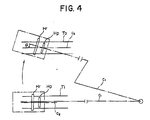
- the above angle gradually increases in accordance with the displacement of the slider 3 toward the periphery of the disc and finally reaches a maximum value ⁇ at the outermost track position T o .
- the centre of the playback head Hp can be exactly positioned with respect to the track centre, but there exists a positional deviation between the centre of the recording head Hr and any other track centre except the innermost track. Consequently, if a recording mode is executed in a state where merely the playback head Hp alone is aligned with the track centre line as shown in figure 3, a newly recorded data track is formed with a positional deviation from the preceding data track.
- Another object of the present invention is to provide a disc drive apparatus with a tracking servomechanism which enables a recording head to scan each data track in a just-tracking state to consequently record data signal properly even by the use of a discrete track disc as a recording medium.
- a disc drive apparatus with a tracking servomechanism comprising at least one disc medium having data surfaces on which a plurality of concentric data tracks are formed, wherein servo signal is recorded on at least one of the data surfaces as well as data signal; transducer means having a first head for reproducing the data signal from the data tracks in a playback mode, and a second head for recording the data signal on the data tracks in a recording mode; a rotary arm for supporting the transducer means at one end thereof while being held rotatably around an axis; actuator motor means for driving the rotary arm in a manner to move the transducer means over the data tracks; servo signal processing means for receiving and processing the servo signal reproduced by the transducer means and outputting a first servo control signal and a second servo control signal; and positioning control means for receiving the first and second servo control signals and controlling the actuator motor means in the playback and recording modes respectively in accordance with the first and second servomechanism
- a disc drive apparatus with a tracking servomechanism comprising at least one disc medium having data surfaces on which a plurality of concentric tracks are formed, each of the tracks being divided into plural data tracks and plural servo tracks, wherein data signal is recorded and reproduced by transducer means on and from the data tracks, while servo signal is prerecorded and reproduced by the transducer means on and from the servo tracks; the transducer means having a first head for reproducing the data signal from the data tracks in a playback mode, and a second head for recording the data signal on the data tracks in a recording mode; a rotary arm for supporting the transducer means at one end thereof while being held rotatably around an axis; actuator motor means for driving the rotary arm in a manner to move the transducer means over the data tracks; servo signal processing means for receiving and processing the servo signal reproduced from the servo tracks and outputting a servo control signal; and positioning control means
- Fig. 1 schematically illustrates the structure of a known disc drive apparatus
- Fig. 2 illustrates a positional state of heads disposed with respect to track position in a conventional example
- Fig. 3(a) illustrates a scanning state of heads in a recording mode in the conventional example
- Fig. 3(b) illustrates a recording state in the conventional example
- Fig. 4 illustrates a positional state of heads disposed with regard to the rotational positions of a support arm in the conventional example
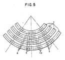
- Fig. 5 illustrates a format on a disc employed in the present invention
- Fig. 6 illustrates a servo pattern of a servo area in the disc format
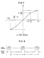
- Fig. 7 graphically shows the off-tracking characteristic of a fine address servo
- Fig. 8 is a timing chart of receiving track addresses in a track seek mode
- Fig. 9 is a circuit block diagram of a tracking servomechanism in an embodiment of the present invention.
- Fig. 10 graphically shows a speed profile characteristic curve obtained in the embodiment of Fig. 9;
- Fig. 11 illustrates how a shift length is calculated in the embodiment of Fig. 9;
- Fig. 12(a) illustrates a scanning state of heads in a recording mode in the embodiment
- Fig. 12(b) illustrates a recording state in the embodiment
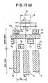
- Fig. 13 (a) illustrates a pattern of an innermost track
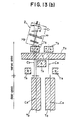
- Fig. 13(b) illustrates a pattern of a track other than the innermost track
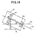
- Fig. 14 illustrates how a shift length is calculated in another embodiment of the present invention.
- Fig. 5 illustrates a format on a disc employed in a disc drive apparatus to which the present invention is applied.
- This format is based on a sector servo system where a multiplicity of tracks T of mutually different radii are formed around the rotation center of the disc 4, and servo areas 5 are formed at equal intervals on each track T of the same radius.
- one sector is constituted of the servo area 5 and a data area 6 posterior thereto, and several tens of sectors are existent in such track.
- Fig. 6 shows a servo pattern of the servo areas 5, and Fig. 7 graphically shows the off-tracking characteristics of a fine address servo.
- a sector head ST with a recorded sector start signal is formed in a head portion of the servo area 5, and address portions SD1 and AD2 with recorded track addresses are formed posterior to the sector head ST.
- address portion AD1 there is formed a portion X where a burst signal representing an odd track is recorded; and immediately posterior to the address portion AD2, there is formed a portion Y where a burst signal representing an even track is recorded.
- the portions A and B are formed at different positions in the longitudinal direction of the track while being spaced apart slightly from the track center line C2 and are provided integrally with the portions A and B of the adjacent track. Meanwhile the portion C is formed continuously with the corresponding portion of the adjacent track so as to be picked up without fail by the playback head Hp regardless of the scanning course thereof.
- a calculation of (A-B)/C is executed and then a value FA proportional to the off-track deviation from the track center line C2 as shown in Fig. 7 is computed to detect a fine address FA.
- TP stands for a track pitch
- TW for a track width.
- the present address of the playback head Hp can be obtained by combining the aforementioned track address with the fine address thus detected.
- Fig. 8 is a timing chart of receiving track addresses in a track seek mode.
- track addresses outputted from the playback head Hp are received synchronously with sector servo pulses in the track seek mode, and the head displacement speed V can be obtained by executing a calculation of (
- Fig. 9 is a circuit block diagram of a track servomechanism.
- an output signal of the playback head Hp is fed via an amplifier 7 to an address sampling circuit 8, which then samples a track address and a fine address.
- the fine address is obtained from a calculation of (A-B)/C as described above, and the resultant value (C to ⁇ 1) is converted into a digital percent value for example by means of an A-D (analog-to-digital) converter.
- Both the track address and the fine address are fed to an adder 9, where the values are added to each other so that the present address is obtained.
- the present address is supplied to a subtracter 10 and a speed calculating circuit 11.
- the subtracter 10 is supplied also with a desired address, and an address difference obtained by subtracting the present address from the desired address is supplied to a root curve generator 12.
- This generator 12 has speed information which corresponds to the address difference and represents the speed profile characteristic shown graphically in Fig. 10.
- the desired speed based on such characteristic is supplied to a subtracter 13.
- the speed calculating circuit 11 receives the present address in synchronism with the sector servo pulse and executes a calculation of
- the present speed thus obtained is supplied to the subtracter 13, which substracts the present speed from the desired speed to calculate the speed difference and then supplies the speed difference data to a gain control amplifier 14.
- a correction value generating circuit 15 which calculates the corrected fine address in accordance with the input track address.
- the calculation of the corrected fine address is executed in the following manner.
- l represents the distance between the playback head Hp and the recording head Hr
- the fine address corresponding to a position S is displaced by such shift length X in the reverse direction is determined to be the corrected fine address.
- the corrected fine address thus obtained is outputted to a subtracter 16; and in a playback mode, a zero value (just-tracking position) is outputted continuously as the corrected fine address.
- the fine address (present fine address) from the address sampling circuit 8 is inputted to the subtracter 16, and the fine address difference obtained by subtracting the present fine address from the desired fine address is outputted to a PID (proportional-integral-derivative) circuit 17.
- Either the output of such PID circuit 17 or the output of the aforementioned gain control amplifier 14 is selected by a selector switch 18, and the selected output is fed via an amplifier 19 to a motor 20 provided for driving the support arm.
- the action of the selector switch 18 is controlled by a switching control circuit 21 which receives the track address difference information from the subtracter 10.
- a control signal is outputted for selectively turning the switch 18 to the side of the gain control amplifier 14.
- another control signal is outputted for changing the switch 18 to the side of the PID circuit 17.
- the selector switch 18 Upon start of the track seek mode during the operation in the recording mode, the selector switch 18 is changed to connect the gain control amplifier 14. And the address sampling circuit 8 samples a track address and a fine address from the playback output picked up by the playback head Hp, whereby the present address is obtained as an output of the adder 9.
- the desired speed data based on the speed profile characteristic is calculated from the address difference data and then is outputted to the subtracter 13. Meanwhile in the speed calculating circuit 11, the present speed is calculated from the present address fed thereto sequentially and then is outputted also to the subtracter 13.
- a driving control signal proportional to the speed difference is outputted from the gain control amplifier 14 to thereby control the rotation speed of the support arm 1.
- This rotation speed corresponding to the displacement speed of the playback head Hp is linearly increased to be approximate to the initial speed in the speed profile characteristic curve as indicated by a one-dot chained line in Fig. 10.
- the control action is so executed as to attain a coincidence between the desired speed and the present speed, whereby the rotation speed is reduced in conformity with the speed profile characteristic.
- the selector switch 18 is changed to the position of the PID circuit 17 by the control signal fed from the switching control circuit 21.
- the decrease of the track address difference to a range of ⁇ 1/2 TP signifies that the playback head Hp has arrived at the desired track, so that the address of the corrected track is inputted from the address sampling circuit 8 to the correction value generating circuit 15. Then this circuit 15 outputs a corrected fine address corresponding to the input track address, and the PID circuit 17 outputs a driving control signal corresponding to the position difference, thereby controlling the rotational position of the support arm 1.
- the center position of the playback head Hp is set properly at the corrected fine address, so that the recording head Hr comes to scan the just-track position exactly on the desired track.
- the data signal is recorded at the position coincident with the track center line C2 as illustrated in Fig. 12(b).
- the correction value generating circuit 15 continuously outputs a zero value as the corrected fine address, so that the playback head Hp can be kept at the just-track position on the track contact line C2 to consequently reproduce a proper playback signal.
- the present invention is applicable also to a different servo system for recording a servo signal in a deep layer of a disc. Also, the present invention is further applicable to another servo system which uses a reference track with calculation of linear interpolation as disclosed in U.S. Patent 4,122,503.
- a playback head and a recording head are secured individually to a rotary support arm in a disc drive apparatus, and such playback head and recording head are moved substantially in the radial direction of a disc by the rotation of the support arm, wherein, during a recording mode, a shift length of the recording head in the radial direction of the disc is calculated with respect to the playback head at a desired track position, and a control action is so executed as to cause off-tracking of the playback head by the calculated shift length in the reverse direction. Consequently, the recording head scans the center line of the servo signal track and writes a data signal at a position coincident with the center of the servo signal track.
- the playback mode there is attainable a remarkable effect of eliminating any noise or read error that may result from the off-track scanning.
- the disc used in this embodiment also has a format pattern of Fig. 5 with servo sectors and data sectors arrayed alternately.
- Fig. 13 illustrates the detail of such format pattern, wherein each servo area E S includes a servo track T S , and each data area E D includes a data track T D .
- the servo tracks T S and the data tracks T D denoted with oblique lines are composed of a magnetic layer, while any other region is composed of a nonmagnetic layer.
- the servo track T S comprises a track address portion T A and three fine address portions A, B, C.
- a track address signal is recorded in the track address portion T S , while burst signals of one frequency are recorded in the fine address portions A, B, C.
- the off-track deviation from the center line C3 of the servo track T S is obtained by calculating an expression (A-B)/C in accordance with the burst signal outputs picked up, and when the width d3 of the fine address portions A and B is rendered equal to the width d2 of the playback head Hp, the servo characteristics can be enhanced to bring about a satisfactory result.
- the data track T D is a region for recording a data signal, and its width is determined to be smaller than the width d1 of the recording head Hr but greater than the width d2 of the playback head Hp.
- the center line C3 of the servo track T S becomes coincident with the center line C2 of the data track T D .
- the center line C3 of the servo track T S is shifted from the center line C2 of the data track T D .
- Such shifted position is denoted by S in Fig. 14 and is set by calculating a shift length X of the recording head Hr in the radial direction of the disc with respect to the playback head Hp at each rotational position of the support arm 1 and then shifting the center line C3 by such calculated length X in the reverse direction.
- the shift length X becomes greater toward the outermost track.
- the playback head Hp When the playback head Hp scans the servo track T S in a playback mode, the playback head Hp picks up a track address signal and a burst signal. The present track address being scanned is identified from the track address signal thus picked up, while the off-track deviation is detected from the burst signal, whereby the playback head Hp is kept scanning the servo track T S in a just-tracking state.
- the playback head Hp and the recording head Hr At the innermost track Ti, as shown in Fig. 13(a), the playback head Hp and the recording head Hr are not shifted in the radial direction of the disc, so that the center line C3 of the servo track T S and the center line C2 of the data track T D are positionally coincident with each other.
- both the playback head Hp and the recording head Hr scan the data track Tp in a just-tracking state. Meanwhile at any track other than the innermost track Ti, the playback head Hp and the recording head Hr are shifted in the radial direction of the disc as shown in Fig. 13(b), but since the center line C3 of the servo track T S is shifted from the center line C2 of the data track T D correspondingly to the above shift length, the playback head Hp scans the off-track position while the recording head Hr scans the just-track position. Consequently, the recording head Hr keeps scanning the just-track position on the data track T D and therefore records data signal properly on the data track T D without any exudation or incomplete erasure in the recording mode.
- the playback head Hp scans the off-track position on the data track T D .
- the playback head Hp is formed to be narrower than the data track width, the end of the playback head Hp never protrudes outside the data track T D to eventually induce none of impediments to the signal reproduction.
- the head positioning system of the present invention calculates a shift length of the recording head in the radial direction of the disc with respect to the playback head at each rotational position of the support arm, and then shifts the center of the servo track in the reverse direction by the calculated shift length from the center of the data track. Therefore the recording head scans the data track in a just-tracking state to eventually ensure a proper data signal recording operation without causing any exudation or incomplete erasure in the recording mode. Meanwhile the playback head scans the data track with an off-track deviation.
- the playback head is generally formed to be narrower than the data track, it is possible for the playback head to scan the data track without protrusion therefrom, hence attaining an advantageous effect that eliminates any impediment to the signal reproduction.
Landscapes
- Moving Of The Head To Find And Align With The Track (AREA)
- Moving Of Head For Track Selection And Changing (AREA)
Priority Applications (1)
| Application Number | Priority Date | Filing Date | Title |
|---|---|---|---|
| EP95107210A EP0670572B1 (fr) | 1989-12-15 | 1990-12-13 | Appareil à entraínement de disque avec servomécanisme d'alignement |
Applications Claiming Priority (4)
| Application Number | Priority Date | Filing Date | Title |
|---|---|---|---|
| JP32521589A JP2697210B2 (ja) | 1989-12-15 | 1989-12-15 | ディスクドライブ装置のトラックサーボ機構 |
| JP325215/89 | 1989-12-15 | ||
| JP32521689A JP2699594B2 (ja) | 1989-12-15 | 1989-12-15 | 磁気ディスク装置のヘッド位置決めシステム |
| JP325216/89 | 1989-12-15 |
Related Child Applications (2)
| Application Number | Title | Priority Date | Filing Date |
|---|---|---|---|
| EP95107210.7 Division-Into | 1990-12-13 | ||
| EP95107210A Division EP0670572B1 (fr) | 1989-12-15 | 1990-12-13 | Appareil à entraínement de disque avec servomécanisme d'alignement |
Publications (3)
| Publication Number | Publication Date |
|---|---|
| EP0433059A2 true EP0433059A2 (fr) | 1991-06-19 |
| EP0433059A3 EP0433059A3 (en) | 1992-03-11 |
| EP0433059B1 EP0433059B1 (fr) | 1996-08-21 |
Family
ID=26571766
Family Applications (2)
| Application Number | Title | Priority Date | Filing Date |
|---|---|---|---|
| EP95107210A Expired - Lifetime EP0670572B1 (fr) | 1989-12-15 | 1990-12-13 | Appareil à entraínement de disque avec servomécanisme d'alignement |
| EP90313549A Expired - Lifetime EP0433059B1 (fr) | 1989-12-15 | 1990-12-13 | Appareil à entraînement à disque avec servo-mécanisme d'alignement |
Family Applications Before (1)
| Application Number | Title | Priority Date | Filing Date |
|---|---|---|---|
| EP95107210A Expired - Lifetime EP0670572B1 (fr) | 1989-12-15 | 1990-12-13 | Appareil à entraínement de disque avec servomécanisme d'alignement |
Country Status (4)
| Country | Link |
|---|---|
| US (1) | US5235478A (fr) |
| EP (2) | EP0670572B1 (fr) |
| KR (1) | KR100215943B1 (fr) |
| DE (2) | DE69028186T2 (fr) |
Cited By (3)
| Publication number | Priority date | Publication date | Assignee | Title |
|---|---|---|---|---|
| EP0611208A3 (fr) * | 1993-02-09 | 1995-07-19 | Sony Corp | Disque de mémorisation d'information et appareil d'enregistrement et de reproduction d'information. |
| EP0777901A4 (fr) * | 1994-08-26 | 1998-03-18 | Quantum Corp | Conformation d'une piste de donnees comprenant des secteurs de commande incorpores correspondant a la structure de la tete magnetoresistive d'une unite de disque |
| EP1093118A3 (fr) * | 1999-10-15 | 2003-12-17 | International Business Machines Corporation | Tête de lecture/écriture et dispositif de stockage |
Families Citing this family (40)
| Publication number | Priority date | Publication date | Assignee | Title |
|---|---|---|---|---|
| JPH04232610A (ja) * | 1990-10-02 | 1992-08-20 | Internatl Business Mach Corp <Ibm> | 情報の読み取り・書き込み装置 |
| EP0564181B1 (fr) * | 1992-03-30 | 1996-11-20 | General Electric Company | Construction d'un dÔme de chambre de combustion |
| US5715105A (en) | 1992-09-28 | 1998-02-03 | Hitachi, Ltd. | Method of and apparatus for recording on and reproducing from disk-type recording medium having recording tracks with sectors each having an ID area and a data area |
| JPH06111502A (ja) * | 1992-09-30 | 1994-04-22 | Sony Corp | 磁気ディスク装置 |
| JPH06150565A (ja) * | 1992-10-30 | 1994-05-31 | Sony Corp | データ記録媒体および記録再生装置 |
| KR0155737B1 (ko) * | 1992-12-23 | 1998-12-15 | 김광호 | 브시알의 트래킹제어방법 및 장치 |
| JP2635942B2 (ja) * | 1994-02-10 | 1997-07-30 | インターナショナル・ビジネス・マシーンズ・コーポレイション | 直接アクセス記憶装置のサーボ位置決めの方法及び装置 |
| US5654842A (en) * | 1994-08-30 | 1997-08-05 | Sony Corporation | Head displacement measuring method and apparatus and data recording/reproducing method and apparatus |
| JPH08147908A (ja) * | 1994-11-17 | 1996-06-07 | Fujitsu Ltd | 記録再生方法及び記録再生装置 |
| BR9609032A (pt) * | 1995-06-06 | 1999-09-14 | Maxtor Corp | Micro posicionador diferencial para cabeçote mr. |
| US5691857A (en) * | 1995-09-29 | 1997-11-25 | Quantum Corporation | Method using matched filters for determining head positioner micro-jog in hard disk drive employing magneto-resistive heads |
| US5771131A (en) * | 1996-07-18 | 1998-06-23 | Quantum Corporation | Tracking in hard disk drive using magnetoresistive heads |
| US5986847A (en) * | 1996-10-18 | 1999-11-16 | Samsung Electronics Co., Ltd. | Method and apparatus for providing read and write skew offset information for a magneto-resistive head |
| US6014283A (en) * | 1997-05-15 | 2000-01-11 | Western Digital Corporation | Non-quadrature servo burst pattern for micro-jogging a magnetoresistive head in a magnetic disk drive |
| JPH1145523A (ja) * | 1997-07-25 | 1999-02-16 | Toshiba Corp | 磁気ディスク装置及び同装置に適用するヘッド位置決め制御システム |
| US6104568A (en) * | 1997-11-14 | 2000-08-15 | Castlewod Systems, Inc. | Servo-burst gray code pattern |
| US6191904B1 (en) | 1997-11-14 | 2001-02-20 | Castlewood Systems, Inc. | Data sector timing compensation technique based upon drive eccentricity |
| US6092195A (en) * | 1997-11-14 | 2000-07-18 | Castlewood Systems, Inc. | Encryption of defects map |
| US6226142B1 (en) | 1997-11-14 | 2001-05-01 | Castlewood Systems, Inc. | Burst pattern for detecting the position of a read/write head relative to a magnetic disk |
| KR100518514B1 (ko) | 1998-02-20 | 2005-11-24 | 삼성전자주식회사 | 하드 디스크 드라이브에서 엑츄에이터 온트랙 제어장치및 그방법 |
| US6429994B1 (en) | 1998-08-14 | 2002-08-06 | Samsung Electronics Co., Ltd | Method and apparatus for providing servo gain linearization for a magneto-resistive head |
| US6441988B2 (en) | 1998-10-07 | 2002-08-27 | Samsung Electronics Co., Ltd. | Method and apparatus for reducing acoustic noise in a hard disk drive |
| US6704354B1 (en) | 1998-10-16 | 2004-03-09 | Samsung Electronics Co., Ltd. | Method and apparatus of providing adaptive equalization using sign permutation filtering |
| US6687079B1 (en) | 1999-10-08 | 2004-02-03 | Samsung Electronics Co., Ltd | Apparatus and method for providing servo gain linearization for a magneto-resistive head |
| US6549364B1 (en) | 1999-12-15 | 2003-04-15 | Samsung Electronics Co., Ltd. | Optimization method and apparatus for a generalized fourier seek trajectory for a hard disk drive servomechanism |
| US6501613B1 (en) | 1999-12-15 | 2002-12-31 | Samsung Electronics Co., Ltd. | Generalized Fourier seek method and apparatus for a hard disk drive servomechanism |
| US6801384B2 (en) | 2000-09-14 | 2004-10-05 | Samsung Electronics Co., Ltd. | Voltage-constrained sinusoidal seek servo in hard disk drives |
| US6982849B2 (en) * | 2000-09-14 | 2006-01-03 | Samsung Electronics Co., Ltd. | Method and apparatus for providing positional information on a disk |
| US6744590B2 (en) | 2000-09-14 | 2004-06-01 | Samsung Electronics Co., Inc. | Seek trajectory adaptation in sinusoidal seek servo hard disk drives |
| US6762902B2 (en) | 2000-12-15 | 2004-07-13 | Samsung Electronics Co., Ltd. | Time-varying, non-synchronous disturbance identification and cancellation in a rotating disk storage device |
| US6724553B2 (en) | 2001-03-26 | 2004-04-20 | Samsung Electronics Co., Ltd. | Method and apparatus for generating the optimum read timing for read and write offset of a magneto resistive head |
| US6700731B2 (en) * | 2001-05-31 | 2004-03-02 | Samsung Electronics Co., Inc. | In-situ linearization of magnetic read/write head transducer position error signal |
| US7430091B2 (en) * | 2005-10-21 | 2008-09-30 | Microsoft Corporation | Method and apparatus for improving the performance of a disk drive |
| JP2007234070A (ja) * | 2006-02-27 | 2007-09-13 | Fujitsu Ltd | ディスリートトラック記録方法、記憶装置及びその製造方法 |
| JP2008016065A (ja) * | 2006-06-30 | 2008-01-24 | Toshiba Corp | ディスク記憶装置及びヘッド位置決め制御方法 |
| JP2008204502A (ja) * | 2007-02-16 | 2008-09-04 | Fujitsu Ltd | 書き込みヘッドの位置決め方法 |
| JP4625816B2 (ja) * | 2007-02-19 | 2011-02-02 | 株式会社東芝 | 原盤の作製方法、磁気記録媒体の製造方法および磁気記録媒体 |
| US8381526B2 (en) * | 2010-02-15 | 2013-02-26 | General Electric Company | Systems and methods of providing high pressure air to a head end of a combustor |
| KR20190115232A (ko) | 2018-04-02 | 2019-10-11 | 송유진 | 거푸집 고정용 브라켓 |
| US11404078B1 (en) * | 2021-08-12 | 2022-08-02 | International Business Machines Corporation | Measuring amplitudes of written tracks in a tape drive to determine errors in read and write elements in the tape drive |
Family Cites Families (6)
| Publication number | Priority date | Publication date | Assignee | Title |
|---|---|---|---|---|
| DE3374731D1 (en) * | 1983-06-30 | 1988-01-07 | Ibm | Track following servo system for a disk file |
| JPS61172282A (ja) * | 1985-01-28 | 1986-08-02 | Seiko Epson Corp | 磁気デイスク用サ−ボ方式 |
| US4701815A (en) * | 1985-03-11 | 1987-10-20 | Sony Corporation | Tracking servo system for disc memory |
| US4802033A (en) * | 1986-11-07 | 1989-01-31 | Eastman Kodak Company | Predictive positioning offset compensation for high TPI disk systems |
| US4912585A (en) * | 1988-04-28 | 1990-03-27 | International Business Machines Corporation | Discrete track thin film magnetic recording disk with embedded servo information |
| JPH06247885A (ja) * | 1993-02-26 | 1994-09-06 | Dainippon Ink & Chem Inc | 4−アルキル−3,5−ジフルオロベンゼン誘導体 |
-
1990
- 1990-12-11 US US07/625,487 patent/US5235478A/en not_active Expired - Lifetime
- 1990-12-13 DE DE69028186T patent/DE69028186T2/de not_active Expired - Fee Related
- 1990-12-13 EP EP95107210A patent/EP0670572B1/fr not_active Expired - Lifetime
- 1990-12-13 DE DE69032955T patent/DE69032955T2/de not_active Expired - Fee Related
- 1990-12-13 EP EP90313549A patent/EP0433059B1/fr not_active Expired - Lifetime
- 1990-12-14 KR KR1019900020573A patent/KR100215943B1/ko not_active Expired - Fee Related
Cited By (4)
| Publication number | Priority date | Publication date | Assignee | Title |
|---|---|---|---|---|
| EP0611208A3 (fr) * | 1993-02-09 | 1995-07-19 | Sony Corp | Disque de mémorisation d'information et appareil d'enregistrement et de reproduction d'information. |
| US5859740A (en) * | 1993-02-09 | 1999-01-12 | Sony Corporation | Information storage disc and information recording and reproducing apparatus |
| EP0777901A4 (fr) * | 1994-08-26 | 1998-03-18 | Quantum Corp | Conformation d'une piste de donnees comprenant des secteurs de commande incorpores correspondant a la structure de la tete magnetoresistive d'une unite de disque |
| EP1093118A3 (fr) * | 1999-10-15 | 2003-12-17 | International Business Machines Corporation | Tête de lecture/écriture et dispositif de stockage |
Also Published As
| Publication number | Publication date |
|---|---|
| EP0670572B1 (fr) | 1999-02-17 |
| DE69032955T2 (de) | 1999-08-26 |
| DE69028186T2 (de) | 1997-02-06 |
| EP0670572A2 (fr) | 1995-09-06 |
| US5235478A (en) | 1993-08-10 |
| EP0433059A3 (en) | 1992-03-11 |
| KR100215943B1 (ko) | 1999-08-16 |
| EP0433059B1 (fr) | 1996-08-21 |
| KR910013170A (ko) | 1991-08-08 |
| EP0670572A3 (fr) | 1996-01-10 |
| DE69028186D1 (de) | 1996-09-26 |
| DE69032955D1 (de) | 1999-03-25 |
Similar Documents
| Publication | Publication Date | Title |
|---|---|---|
| US5235478A (en) | Disc drive apparatus with servo tracks offset from data tracks | |
| US6529341B1 (en) | Magnetic recording/reproduction device using preformat information | |
| JPS61144781A (ja) | デイスク装置 | |
| US6373648B2 (en) | Disk head assembly with multiple read and/or write transducers for improved performance | |
| JPH04274064A (ja) | グレイコードを用いたディスクドライブサーボシステム | |
| US5748398A (en) | Method for writing servo signals onto a magnetic disk and magnetic disk drive equipped with magnetic disk(s) having servo pattern recorded by the method | |
| US8559125B2 (en) | Seamless and untrimmed primary servo burst with multiple secondary servo bursts | |
| KR930001151B1 (ko) | 자기 기록 재생장치 | |
| AU630335B2 (en) | Tracking servo control for disc drive | |
| KR930003469B1 (ko) | 기록장치 | |
| JP3292741B2 (ja) | 磁気ディスク装置 | |
| JPH09282818A (ja) | 磁気ディスク装置及びそれに適用するヘッド位置決め制御システム | |
| JP2835763B2 (ja) | 磁気ディスク装置 | |
| JP2697210B2 (ja) | ディスクドライブ装置のトラックサーボ機構 | |
| JP2553721B2 (ja) | トラック追従制御装置 | |
| JP2699594B2 (ja) | 磁気ディスク装置のヘッド位置決めシステム | |
| EP0250138B1 (fr) | Servosystème pour un entraînement de disque rigide | |
| JPS6212970A (ja) | デイスク装置 | |
| JP2695486B2 (ja) | データ面サーボ制御方式のディスク装置 | |
| JP2539029B2 (ja) | 磁気ディスク装置 | |
| JPS6356884A (ja) | デイスク装置 | |
| JPH06139733A (ja) | ハードディスク装置 | |
| JPS6332772A (ja) | デイスク装置 | |
| JPH09161249A (ja) | 磁気ディスク装置 | |
| JPH081693B2 (ja) | 磁気再生装置 |
Legal Events
| Date | Code | Title | Description |
|---|---|---|---|
| PUAI | Public reference made under article 153(3) epc to a published international application that has entered the european phase |
Free format text: ORIGINAL CODE: 0009012 |
|
| AK | Designated contracting states |
Kind code of ref document: A2 Designated state(s): DE FR GB |
|
| PUAL | Search report despatched |
Free format text: ORIGINAL CODE: 0009013 |
|
| AK | Designated contracting states |
Kind code of ref document: A3 Designated state(s): DE FR GB |
|
| 17P | Request for examination filed |
Effective date: 19920814 |
|
| 17Q | First examination report despatched |
Effective date: 19940915 |
|
| GRAH | Despatch of communication of intention to grant a patent |
Free format text: ORIGINAL CODE: EPIDOS IGRA |
|
| GRAH | Despatch of communication of intention to grant a patent |
Free format text: ORIGINAL CODE: EPIDOS IGRA |
|
| GRAA | (expected) grant |
Free format text: ORIGINAL CODE: 0009210 |
|
| AK | Designated contracting states |
Kind code of ref document: B1 Designated state(s): DE FR GB |
|
| XX | Miscellaneous (additional remarks) |
Free format text: TEILANMELDUNG 95107210.7 EINGEREICHT AM 13/12/90. |
|
| REF | Corresponds to: |
Ref document number: 69028186 Country of ref document: DE Date of ref document: 19960926 |
|
| ET | Fr: translation filed |
Free format text: CORRECTIONS |
|
| PLBE | No opposition filed within time limit |
Free format text: ORIGINAL CODE: 0009261 |
|
| STAA | Information on the status of an ep patent application or granted ep patent |
Free format text: STATUS: NO OPPOSITION FILED WITHIN TIME LIMIT |
|
| 26N | No opposition filed | ||
| REG | Reference to a national code |
Ref country code: GB Ref legal event code: IF02 |
|
| PGFP | Annual fee paid to national office [announced via postgrant information from national office to epo] |
Ref country code: DE Payment date: 20021219 Year of fee payment: 13 |
|
| PGFP | Annual fee paid to national office [announced via postgrant information from national office to epo] |
Ref country code: GB Payment date: 20031210 Year of fee payment: 14 Ref country code: FR Payment date: 20031210 Year of fee payment: 14 |
|
| PG25 | Lapsed in a contracting state [announced via postgrant information from national office to epo] |
Ref country code: DE Free format text: LAPSE BECAUSE OF NON-PAYMENT OF DUE FEES Effective date: 20040701 |
|
| PG25 | Lapsed in a contracting state [announced via postgrant information from national office to epo] |
Ref country code: GB Free format text: LAPSE BECAUSE OF NON-PAYMENT OF DUE FEES Effective date: 20041213 |
|
| GBPC | Gb: european patent ceased through non-payment of renewal fee |
Effective date: 20041213 |
|
| PG25 | Lapsed in a contracting state [announced via postgrant information from national office to epo] |
Ref country code: FR Free format text: LAPSE BECAUSE OF NON-PAYMENT OF DUE FEES Effective date: 20050831 |
|
| REG | Reference to a national code |
Ref country code: FR Ref legal event code: ST |