EP0433532A1 - Capuchon pour instruments à écrire à encre - Google Patents
Capuchon pour instruments à écrire à encre Download PDFInfo
- Publication number
- EP0433532A1 EP0433532A1 EP90104659A EP90104659A EP0433532A1 EP 0433532 A1 EP0433532 A1 EP 0433532A1 EP 90104659 A EP90104659 A EP 90104659A EP 90104659 A EP90104659 A EP 90104659A EP 0433532 A1 EP0433532 A1 EP 0433532A1
- Authority
- EP
- European Patent Office
- Prior art keywords
- cap
- axial
- retaining clip
- cap according
- ventilation
- Prior art date
- Legal status (The legal status is an assumption and is not a legal conclusion. Google has not performed a legal analysis and makes no representation as to the accuracy of the status listed.)
- Granted
Links
Images






Classifications
-
- B—PERFORMING OPERATIONS; TRANSPORTING
- B43—WRITING OR DRAWING IMPLEMENTS; BUREAU ACCESSORIES
- B43K—IMPLEMENTS FOR WRITING OR DRAWING
- B43K23/00—Holders or connectors for writing implements; Means for protecting the writing-points
- B43K23/08—Protecting means, e.g. caps
- B43K23/12—Protecting means, e.g. caps for pens
- B43K23/122—Protecting means, e.g. caps for pens with means for preventing choking
- B43K23/124—Protecting means, e.g. caps for pens with means for preventing choking comprising an air passage
-
- B—PERFORMING OPERATIONS; TRANSPORTING
- B43—WRITING OR DRAWING IMPLEMENTS; BUREAU ACCESSORIES
- B43K—IMPLEMENTS FOR WRITING OR DRAWING
- B43K23/00—Holders or connectors for writing implements; Means for protecting the writing-points
- B43K23/08—Protecting means, e.g. caps
- B43K23/12—Protecting means, e.g. caps for pens
- B43K23/126—Protecting means, e.g. caps for pens with clips
Definitions
- the invention relates generally to an improvement to caps for writing instruments containing ink and in particular to a cap with a safety ventilation device in order to facilitate an air flow along the cap, if the latter has lodged in a person's windpipe, for example of a child, when swallowed accidentally.
- a cap of the type mentioned at the beginning should be provided by the invention, which with a simple construction, which is favourable from the manufacturing point of view, on the one hand can prevent drying up of the writing part of writing instruments containing ink, in a problem-free manner and on the other hand offers the guarantee that if swallowed, sufficient air for breathing may flow along the cap.
- the cap according to the invention is characterised by the fact that with the exception of its insertion end, the cap is closed on all sides and the safety ventilation device comprises at least one axial ventilation path on the outside of the cap, which along at least part of its axial extent has a peripherally open cross-sectional configuration such that in conjunction with a covering placed around the cap, a cross-sectional area is defined in each radial plane for the ventilation with a throughflow capacity corresponding to the air requirement of a person.
- the high sealing function of the cap according to the invention with respect to the writing part of a writing instrument inserted therein results from the fact that with the exception of its insertion end, in contrast to the known solutions with a safety function, the cap is closed on all sides, i.e. it is free from perforations leading into the inside of the cap.
- the cap therefore corresponds in its sealing function to the caps used hitherto in writing instruments without a safety ventilation device.
- the existing caps can therefore be replaced without modification of the writing instruments, by safety caps according to the invention.
- the ventilation path extends exclusively on the outside of the cap and indeed in the form of an air passage, which has an open cross-sectional configuration, i.e.
- the passage when considered in a radial plane is not closed on its periphery such as for example in the case of a tube, but is open and thus accessible from outside.
- the passage also has such a cross-sectional configuration that if a wrapper is wrapped around the cap, an air way with a cross-sectional area, which is adapted to the air requirement of a person, is always available.
- the basically open air passage on the outer side of the cap cannot be blocked by the windpipe, since the covering corresponding to the windpipe only covers the open side of the air passage or thus closes the latter peripherally, so that a path always remains for the flow of air for breathing along the cap.
- the construction of the safety ventilation device according to the invention has advantages both as regards manufacturing techniques, since it is not necessary to form any cavities which are not easily accessible, as well as an improved safety function, in that the regions which are critical for this, can be checked at a glance as regards their functional state, for example for blocking deposits and the like.
- a further advantage of the cap according to the invention is the relatively high freedom as regards the respective design of the cap.
- a cap comprises a substantially plate-shaped retaining clip, which is attached close to the closed axial end of the cap and whereof the spring deflection with respect to the cap is limited by maintaining a minimum spacing with respect to the cap surface.
- the retaining clip in its base attachment region, the retaining clip comprises a perforation aligned substantially axially, so that a ventilation path is provided, which comprises the perforation and the gap below the retaining clip which is open (in the peripheral direction of the cap).
- the free end of the retaining clip i.e. the end remote from the base attachment region, is located on or at a short distance from the insertion end of the cap.
- the perforation may be constructed so that it forms a pair of web-like areas in the base attachment region, which provide a resilient connection between the retaining clip and cap.
- the cap with the aforedescribed construction is placed on a writing instrument containing ink, for example a fountain pen, then the sensitive writing part arrives in an interior space, which as in the case of conventional caps, is sealed hermetically with respect to the atmosphere at the time of insertion of the writing instrument.
- the writing instrument consequently remains in a usable state without any risk of drying-up, so that one can immediately begin to write after removing the cap.
- a child should accidentally swallow the cap there is no danger that the cap will block the windpipe, since the axial perforation in the base attachment region and the gap between the retaining clip and the surface of the cap cannot be closed by the windpipe.
- the resilient connecting webs in the base attachment region contribute to preventing injuries to the windpipe or gullet by the retaining clip of a swallowed cap or at least to substantially alleviate such injuries, since due to this the retaining clip acquires adequate flexibility.
- At least one axial rib projecting substantially radially from the outer side of the cap may be provided.
- the ventilation path is defined by the side faces of the ribs and the adjoining surface of the cap.
- the effect of the rib is that when the cap is swallowed, the windpipe is kept away from its surface in certain regions, so that an air passage remains, which has a quasi tent-shaped cross-section, when considered in a radial plane.
- the rib may also have a substantially T-shaped or mushroom-shaped cross-section and consequently defines an airway, which is open in the peripheral direction.
- a development of this embodiment also provides that a pair of axial ribs arranged in parallel one beside the other at a short distance apart are provided, which define a channel-like ventilation path therebetween.
- these ribs may form a pair of airways on the outside of the ribs and an airway with a channel-shaped cross-section formed between the ribs.
- the outer side faces of the pair of ribs pass substantially continuously, for example tangentially into the surface of the cap. In this case, the airway is defined by the region between the pair of ribs.
- a further embodiment of the invention provides a plurality of axial indentations or grooves provided in the outer surface of the cap and spaced apart peripherally. These grooves, which extend from one axial end to the other axial end of the cap, have a similar effect to the aforementioned ribs, in that they prevent a covering placed around them or the inner wall of the windpipe along the entire periphery of the cap from bearing in a tight manner against its surface.
- the grooves may co-operate with a substantially plate-shaped retaining clip, which is defined laterally by an adjoining pair of axial grooves. A transverse connection between the adjoining pair of grooves is additionally created by the gap between the retaining clip and cap surface.
- One common feature of all the embodiments of the invention is that, when considered in any radial plane of the cap, the cross-sectional area of the ventilation paths created is greater than or equal to approximately 3.4 mm2, in order to ensure the minimum necessary air requirement of a person, in particular of a child, along the cap.
- a further common feature consists in that the ventilation path ends at a distance less than or equal to approximately 2 mm from the insertion end of the cap, since otherwise it is not ensured that even at the insertion end of the cap, the windpipe is kept at a suitable distance from its surface.
- the cap bears the general reference numeral 1.
- the cap 1 has a substantially tubular or cylindrical shape with an outer diameter of normally up to 16 mm.
- the cap is closed at one axial end, whereas the other axial end is provided with an insertion opening 4.
- the writing part 9 of the writing instrument 8 supporting the writing point 10 is inserted by way of the insertion opening 4.
- a retaining clip 2 extending coaxially to the cap 1 is attached by its base region 12 to the closed top of the cap 1.
- the base region 12 may be curved and contains a perforation 3 aligned substantially axially.
- the airway of the present embodiment comprises the perforation 3 and the gap 6 connected thereto between the retaining clip 2 and the outer surface of the cap 1.
- the airway should have a cross-sectional area of at least 3.4 mm2, preferably greater equal to 6.8 mm2, at any axial point along the cap.
- the retaining clip 2 extends along the outside of the cap 1 as far as a point close to the insertion opening 4. In order that an adequate airway is guaranteed between the edge of the insertion opening 4 and the free end of the retaining clip 2, the spacing m of the free axial end of the retaining clip 2 from the insertion opening 4 should amount to less than 2 mm.
- the reference numeral 5 relates to the inside of the cap, which when the writing part 9 is inserted, is sealed with respect to the atmosphere by a peripheral region of the writing instrument 8.
- the reference numerals 13 relate to web-like areas, which are formed by the perforation 3 provided in the base attachment region 12 of the retaining clip 2 and which connect the retaining clip 2 resiliently to the cap.
- the cap 1 with the inserted writing instrument 8 can be clipped to an article of clothing by means of the retaining clip 2.
- the perforation 3 in the base attachment region 12 and the gap 6 between the retaining clip 2 and outer surface of the cap 1 form an airway, so that the air passage necessary for the child to breathe is ensured and the danger of asphyxiation does not exist. Furthermore, since the retaining clip extends close up to the insertion opening 4 of the cap, even close to this end of the cap, the airway is not closed by the windpipe. Since the retaining clip is held resiliently by the connecting webs 13, even in the case of contact of the tip of the retaining clip 2 with the gullet or windpipe, the danger of asphyxiation is substantially reduced.
- the reference numeral 7 relates to a projection, which keeps the retaining clip at a suitable distance from the surface of the cap 1.
- the second embodiment of the invention is illustrated in Figures 5 to 8.
- the difference from the embodiment according to Figures 1 to 4 consists in that the retaining clip 2 is attached by way of a radial base attachment region 12 to the top of the cap 1.
- the retaining clip 2 extends along the cap 1.
- an axial perforation 3 Provided in the attachment base region 12 of the retaining clip 2 is an axial perforation 3, which is in axial alignment with the gap 6 between the retaining clip 2 and outer side of the cap, so that an airway is formed, which extends as far as the insertion opening 4 of the cap 1.
- resilient connecting webs 13 are formed in the base attachment region 12 of the retaining clip 2 on both sides of the perforation 3, which connecting webs facilitate clipping of the cap to an article of clothing and at the same time alleviate the danger of injury to the windpipe, if the cap is accidentally swallowed.
- the third embodiment of the invention is illustrated in Figures 9 to 12.
- This embodiment differs from the embodiment according to Figures 5 to 8 substantially solely in that between the gap 6 and the perforation 3 in the base attachment region 12, an enlarged air space 14 is provided at the top of the cap 1.
- the perforation 3 can consequently be offset somewhat radially with respect to the gap 6.
- the resilient connecting webs 13 are provided in the base region 12 at the sides of the perforation 3.
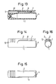
- the base attachment region 12 of the retaining clip 2 is constructed as an annular wall part extending axially, close to the closed top of the cap 1, which defines an axial through passage 3 together with the cap surface.
- the through passage 3 and the gap 6 below the retaining clip 2 form the axial airway.
- FIGS 17 to 19 show the fifth embodiment of the invention.
- the reference numeral 101 relates to the cap, which is substantially cigar-shaped and whereof the outer diameter normally amounts to no more than 16 mm.
- the reference numeral 102 relates to a pair of projecting ribs formed on the outer surface of the cap 101, which extend axially along the cap at diametrically opposed points of its periphery.
- the reference numeral 105 designates a flat portion of the surface of the cap 101 associated with each rib 102, close to its closed top end.
- the open insertion end of the cap 101 bears the reference numeral 104.
- an outer annular end face may remain between the insertion opening 104 and the facing end of the ribs 102, which end face has an axial length which should not exceed 2 mm.
- the flat portions 105 allow a reduction in the height of the ribs 102.
- the interior of the cap is hermetically sealed and consequently drying-up of the writing point is effectively prevented. If the cap 101 is accidentally swallowed, an axial airway remains between the side faces of each rib 102 and the adjacent outer surface of the cap 101 on account of the spreading action of the ribs, which is indicated at 106. In conjunction with a covering placed around it, the airway creates a cross-sectional area for the passage of air, which due to suitable dimensions of the ribs 102 is designed such that it amounts to at least 3.4 mm2 , preferably 6.8 mm2 at each axial point of the cap 101.
- Figures 20 to 22 show the sixth embodiment of the invention.
- This embodiment differs from the aforedescribed fifth embodiment substantially solely due to the fact that instead of a pair of diametrically opposed ribs, a pair of axial ribs 102 lying parallel one beside the other with a suitable short spacing is provided.
- the ribs 102 therefore define between them an axial air passage 106 with a suitable cross-sectional area in addition to the airways along the outer side faces of the ribs 102.
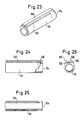
- Figures 23 to 26 show the seventh embodiment of the invention.
- a rib 102 extending axially, with a substantially T-shaped or mushroom-shaped cross-section.
- the rib 102 has a flat, plate-like upper part 108, which is connected by way of a radial web 109 to the surface of the cap 101.
- gaps 106 are provided on both sides of the web 109 between the plate-shaped upper part 108 and the cap surface, which define axial airways.
- the cap 101 itself has a substantially cylindrical configuration with a closed end and an open insertion end 104 for the writing part of a writing instrument.
- Air may also flow through the air gap below the plate-like upper part 108 on both sides of the web 109 of the rib 102 extending from the top end as far as the insertion end 104 of the cap 101, if the cap lodges in the windpipe as a result of being swallowed accidentally. Since, under these circumstances, the surface of the plate-like upper part 108 bears against the inner wall of the windpipe, the risk of injury is substantially reduced.
- Figures 27 to 30 show the eighth embodiment of the invention.
- This embodiment is a modification of the embodiment according to Figures 20 to 22, in which the outer side faces 110 of the pair of ribs 102 extending in parallel one beside the other at a distance apart are shaped so that they pass tangentially or continuously into the outer surface of the cap 101, so that the airway is defined substantially solely by the passage 106 enclosed between the ribs 102.
- the shaping of the side faces 110 of the ribs 102 together with the chamfering of the axial ends of the ribs reduces the danger of injury to the windpipe or gullet, if the cap 101 is swallowed accidentally.
- the cap 101 in the present embodiment may have a substantially cylindrical shape.
- a ninth embodiment of the invention is illustrated in Figures 31 to 34.
- the reference numeral 201 relates to a substantially cylindrical cap with a closed axial top and an open insertion end bearing the reference numeral 204.
- the outer diameter of the cap 201 normally amounts to no more than 16 mm.
- Attached close to the top end of the cap 201 is a retaining clip 202, which is held by way of a projection 207 formed on the surface of the cap 201, at a suitable distance from the surface of the cap 201. If the writing part of a writing instrument (not shown) is inserted in the insertion opening 204 of the cap 201, consequently the interior of the cap 201 is hermetically sealed. If desired, there may be provided within the cap 201 an additional inner cap, which receives the front part of the writing instrument.
- the reference numeral 206 relates to indentations or grooves in the outer surface of the cap 201, which extend along the cap from its top end to the insertion opening 204 and are distributed peripherally at a suitable distance from each other.
- the free end of the retaining clip 2 may terminate at a distance m from the insertion opening 204, which distance should not amount to more than 2 mm.
- a covering H placed around the cap 201 is indicated by the broken line in Figure 34.
- the course of the covering H corresponds substantially to that of the inner surface of the windpipe in the region of a swallowed cap 201.
- axial airways are formed between the covering H and the grooves or indentations 206, through which airways air for breathing may flow, since at these points direct contact of the windpipe with the surface of the cap 201 is prevented.
- the cross-sectional area of the airway should amount to at least 3.4 mm2.
- a pair of indentations or grooves 206 are provided adjoining the retaining clip 202 laterally, so that the gap between the retaining clip 202 and the surface of the cap 201 may serve as a transverse passage for an airflow between the adjoining pair of grooves 206.
- a covering H is shown solely in Figure 34, it will be understood that similar coverings can also be shown in the other embodiments, in order to define the free cross-sectional areas, which remain for a person to breathe, if this person has accidentally swallowed a cap of the type according to the invention.
- the cross-sectional area available as a whole for the ventilation in a radial plane of the cap does not need to be the same along the cap between the axial ends. It is important that a cross-sectional area for the ventilation is available at each axial point of the cap, which area has a throughflow capacity which corresponds at least to the minimum air requirement of a person.
- the minimum cross-sectional area should amount to 3.4 mm2 , preferably 6.8 mm2
- the axial airways on the outside of the cap according to the invention have axial, open ends, which cannot be closed by a covering H placed around them, respectively by the inner wall of the windpipe of a person.
Landscapes
- Clips For Writing Implements (AREA)
- Coating Apparatus (AREA)
- Pens And Brushes (AREA)
Priority Applications (2)
| Application Number | Priority Date | Filing Date | Title |
|---|---|---|---|
| EP95103513A EP0679538B1 (fr) | 1989-12-16 | 1990-03-12 | Capuchon pour instruments à écrire contenant de l'encre |
| EP94113647A EP0630761B1 (fr) | 1989-12-16 | 1990-03-12 | Capuchon pour instruments à écrire contenant de l'encre |
Applications Claiming Priority (6)
| Application Number | Priority Date | Filing Date | Title |
|---|---|---|---|
| JP1324901A JPH0825353B2 (ja) | 1989-12-16 | 1989-12-16 | インキを内蔵する筆記具用キャップ |
| JP324901/89 | 1989-12-16 | ||
| JP1325960A JP2539275B2 (ja) | 1989-12-18 | 1989-12-18 | インキ内蔵筆記具用キャップ |
| JP1989144989U JP2512711Y2 (ja) | 1989-12-18 | 1989-12-18 | インキを内蔵する筆記具用キャップ |
| JP325960/89 | 1989-12-18 | ||
| JP144989/89 | 1989-12-18 |
Related Child Applications (2)
| Application Number | Title | Priority Date | Filing Date |
|---|---|---|---|
| EP95103513.8 Division-Into | 1990-03-12 | ||
| EP94113647.5 Division-Into | 1990-03-12 |
Publications (2)
| Publication Number | Publication Date |
|---|---|
| EP0433532A1 true EP0433532A1 (fr) | 1991-06-26 |
| EP0433532B1 EP0433532B1 (fr) | 1996-07-03 |
Family
ID=27318920
Family Applications (3)
| Application Number | Title | Priority Date | Filing Date |
|---|---|---|---|
| EP94113647A Expired - Lifetime EP0630761B1 (fr) | 1989-12-16 | 1990-03-12 | Capuchon pour instruments à écrire contenant de l'encre |
| EP19900104659 Expired - Lifetime EP0433532B1 (fr) | 1989-12-16 | 1990-03-12 | Capuchon pour instruments à écrire à encre |
| EP95103513A Expired - Lifetime EP0679538B1 (fr) | 1989-12-16 | 1990-03-12 | Capuchon pour instruments à écrire contenant de l'encre |
Family Applications Before (1)
| Application Number | Title | Priority Date | Filing Date |
|---|---|---|---|
| EP94113647A Expired - Lifetime EP0630761B1 (fr) | 1989-12-16 | 1990-03-12 | Capuchon pour instruments à écrire contenant de l'encre |
Family Applications After (1)
| Application Number | Title | Priority Date | Filing Date |
|---|---|---|---|
| EP95103513A Expired - Lifetime EP0679538B1 (fr) | 1989-12-16 | 1990-03-12 | Capuchon pour instruments à écrire contenant de l'encre |
Country Status (3)
| Country | Link |
|---|---|
| EP (3) | EP0630761B1 (fr) |
| DE (3) | DE69027657T2 (fr) |
| ES (3) | ES2105796T3 (fr) |
Cited By (4)
| Publication number | Priority date | Publication date | Assignee | Title |
|---|---|---|---|---|
| DE9115124U1 (de) * | 1991-12-05 | 1992-04-02 | Pelikan Ag, 3000 Hannover | Verschlußkappe für ein Schreibgerät |
| EP0481479A1 (fr) * | 1990-10-17 | 1992-04-22 | Tombow Pencil Co., Ltd. | Capuchon de sécurité pour stylo |
| US5316402A (en) * | 1991-12-13 | 1994-05-31 | Tombow Pencil Co., Ltd. | Penholder cap |
| US5632565A (en) * | 1995-09-07 | 1997-05-27 | Colleague Iowa, Inc. | Removable cap with fluid passage |
Citations (5)
| Publication number | Priority date | Publication date | Assignee | Title |
|---|---|---|---|---|
| GB2174374A (en) * | 1985-04-12 | 1986-11-05 | Platignum Plc | Closure cap |
| EP0319311A1 (fr) * | 1987-12-04 | 1989-06-07 | Douglas E.J. Ashpole | Capuchon pour instrument à écrire |
| DE8908065U1 (de) * | 1989-07-01 | 1989-09-14 | J. S. Staedtler GmbH & Co, 8500 Nürnberg | Schreibgerätekappe |
| DE8907626U1 (de) * | 1989-06-22 | 1990-07-26 | J. S. Staedtler GmbH & Co, 8500 Nürnberg | Vorrichtung zum Verhindern des Erstickens bei Schreibgerätekappen |
| EP0395797A1 (fr) * | 1989-04-29 | 1990-11-07 | A.W. Faber - Castell GmbH & Co. | Capuchon pour instruments à écrire ou analogues |
Family Cites Families (1)
| Publication number | Priority date | Publication date | Assignee | Title |
|---|---|---|---|---|
| JPH01169386U (fr) * | 1988-05-21 | 1989-11-29 |
-
1990
- 1990-03-12 EP EP94113647A patent/EP0630761B1/fr not_active Expired - Lifetime
- 1990-03-12 DE DE1990627657 patent/DE69027657T2/de not_active Expired - Fee Related
- 1990-03-12 EP EP19900104659 patent/EP0433532B1/fr not_active Expired - Lifetime
- 1990-03-12 ES ES95103513T patent/ES2105796T3/es not_active Expired - Lifetime
- 1990-03-12 ES ES94113647T patent/ES2111222T3/es not_active Expired - Lifetime
- 1990-03-12 DE DE1990631182 patent/DE69031182T2/de not_active Expired - Fee Related
- 1990-03-12 EP EP95103513A patent/EP0679538B1/fr not_active Expired - Lifetime
- 1990-03-12 ES ES90104659T patent/ES2088912T3/es not_active Expired - Lifetime
- 1990-03-12 DE DE1990631741 patent/DE69031741T2/de not_active Expired - Fee Related
Patent Citations (5)
| Publication number | Priority date | Publication date | Assignee | Title |
|---|---|---|---|---|
| GB2174374A (en) * | 1985-04-12 | 1986-11-05 | Platignum Plc | Closure cap |
| EP0319311A1 (fr) * | 1987-12-04 | 1989-06-07 | Douglas E.J. Ashpole | Capuchon pour instrument à écrire |
| EP0395797A1 (fr) * | 1989-04-29 | 1990-11-07 | A.W. Faber - Castell GmbH & Co. | Capuchon pour instruments à écrire ou analogues |
| DE8907626U1 (de) * | 1989-06-22 | 1990-07-26 | J. S. Staedtler GmbH & Co, 8500 Nürnberg | Vorrichtung zum Verhindern des Erstickens bei Schreibgerätekappen |
| DE8908065U1 (de) * | 1989-07-01 | 1989-09-14 | J. S. Staedtler GmbH & Co, 8500 Nürnberg | Schreibgerätekappe |
Cited By (4)
| Publication number | Priority date | Publication date | Assignee | Title |
|---|---|---|---|---|
| EP0481479A1 (fr) * | 1990-10-17 | 1992-04-22 | Tombow Pencil Co., Ltd. | Capuchon de sécurité pour stylo |
| DE9115124U1 (de) * | 1991-12-05 | 1992-04-02 | Pelikan Ag, 3000 Hannover | Verschlußkappe für ein Schreibgerät |
| US5316402A (en) * | 1991-12-13 | 1994-05-31 | Tombow Pencil Co., Ltd. | Penholder cap |
| US5632565A (en) * | 1995-09-07 | 1997-05-27 | Colleague Iowa, Inc. | Removable cap with fluid passage |
Also Published As
| Publication number | Publication date |
|---|---|
| EP0630761A2 (fr) | 1994-12-28 |
| EP0630761B1 (fr) | 1997-11-19 |
| ES2088912T3 (es) | 1996-10-01 |
| DE69031182T2 (de) | 1998-01-08 |
| DE69031741T2 (de) | 1998-04-09 |
| EP0679538A1 (fr) | 1995-11-02 |
| DE69031741D1 (de) | 1998-01-02 |
| DE69031182D1 (de) | 1997-09-04 |
| EP0630761A3 (fr) | 1995-02-01 |
| ES2111222T3 (es) | 1998-03-01 |
| EP0679538B1 (fr) | 1997-07-30 |
| ES2105796T3 (es) | 1997-10-16 |
| EP0433532B1 (fr) | 1996-07-03 |
| DE69027657D1 (de) | 1996-08-08 |
| DE69027657T2 (de) | 1996-10-31 |
Similar Documents
| Publication | Publication Date | Title |
|---|---|---|
| US5066156A (en) | Writing instrument cap | |
| US5076721A (en) | Writing instrument cap suitable to let a flow of air pass through it | |
| US5127754A (en) | Writing instrument's cap with safety vent | |
| EP0319311A1 (fr) | Capuchon pour instrument à écrire | |
| EP0433532A1 (fr) | Capuchon pour instruments à écrire à encre | |
| US5054949A (en) | Cap for writing implement with air vent | |
| US5000603A (en) | Removable cap of writing instrument | |
| JPH0712062Y2 (ja) | キャップ | |
| US5927888A (en) | Cap for writing instruments | |
| KR940005251Y1 (ko) | 잉크 내장 필기구용 캡 | |
| JPH03187796A (ja) | インキ内蔵筆記具用キャップ | |
| EP0481479A1 (fr) | Capuchon de sécurité pour stylo | |
| JPH02301497A (ja) | 筆記用具類に用いられる閉鎖キヤツプ | |
| JPH0721391U (ja) | 筆記具のキャップ | |
| JPH10166785A (ja) | 筆記具等のキャップ | |
| JP3786496B2 (ja) | 筆記具のキャップ | |
| KR930008473Y1 (ko) | 잉크 내장 필기구용 캡 | |
| KR920003778Y1 (ko) | 필기구 등의 안전캡 | |
| JP3611221B2 (ja) | 筆記具の口先具 | |
| EP2429832B1 (fr) | Capuchon de fermeture | |
| JPH0732138Y2 (ja) | 筆記具用キャップ | |
| JPH0939479A (ja) | 筆記具用キャップ | |
| JPH0755117Y2 (ja) | 筆記具用キャップ | |
| JPH10272888A (ja) | 筆記具用キャップ | |
| JPH11301170A (ja) | 筆記具用キャップ |
Legal Events
| Date | Code | Title | Description |
|---|---|---|---|
| PUAI | Public reference made under article 153(3) epc to a published international application that has entered the european phase |
Free format text: ORIGINAL CODE: 0009012 |
|
| AK | Designated contracting states |
Kind code of ref document: A1 Designated state(s): CH DE ES FR GB IT LI |
|
| 17P | Request for examination filed |
Effective date: 19911022 |
|
| 17Q | First examination report despatched |
Effective date: 19930716 |
|
| GRAA | (expected) grant |
Free format text: ORIGINAL CODE: 0009210 |
|
| AK | Designated contracting states |
Kind code of ref document: B1 Designated state(s): CH DE ES FR GB IT LI |
|
| XX | Miscellaneous (additional remarks) | ||
| REG | Reference to a national code |
Ref country code: CH Ref legal event code: NV Representative=s name: ROTTMANN, ZIMMERMANN + PARTNER AG |
|
| REF | Corresponds to: |
Ref document number: 69027657 Country of ref document: DE Date of ref document: 19960808 |
|
| ITF | It: translation for a ep patent filed | ||
| ET | Fr: translation filed | ||
| REG | Reference to a national code |
Ref country code: ES Ref legal event code: FG2A Ref document number: 2088912 Country of ref document: ES Kind code of ref document: T3 |
|
| REG | Reference to a national code |
Ref country code: ES Ref legal event code: FG2A Ref document number: 2088912 Country of ref document: ES Kind code of ref document: T3 |
|
| PGFP | Annual fee paid to national office [announced via postgrant information from national office to epo] |
Ref country code: FR Payment date: 19970129 Year of fee payment: 8 |
|
| PGFP | Annual fee paid to national office [announced via postgrant information from national office to epo] |
Ref country code: CH Payment date: 19970303 Year of fee payment: 8 |
|
| PGFP | Annual fee paid to national office [announced via postgrant information from national office to epo] |
Ref country code: ES Payment date: 19970311 Year of fee payment: 8 |
|
| PLBE | No opposition filed within time limit |
Free format text: ORIGINAL CODE: 0009261 |
|
| STAA | Information on the status of an ep patent application or granted ep patent |
Free format text: STATUS: NO OPPOSITION FILED WITHIN TIME LIMIT |
|
| 26N | No opposition filed | ||
| PG25 | Lapsed in a contracting state [announced via postgrant information from national office to epo] |
Ref country code: ES Free format text: LAPSE BECAUSE OF EXPIRATION OF PROTECTION Effective date: 19980313 |
|
| PG25 | Lapsed in a contracting state [announced via postgrant information from national office to epo] |
Ref country code: LI Free format text: LAPSE BECAUSE OF NON-PAYMENT OF DUE FEES Effective date: 19980331 Ref country code: FR Free format text: THE PATENT HAS BEEN ANNULLED BY A DECISION OF A NATIONAL AUTHORITY Effective date: 19980331 Ref country code: CH Free format text: LAPSE BECAUSE OF NON-PAYMENT OF DUE FEES Effective date: 19980331 |
|
| REG | Reference to a national code |
Ref country code: CH Ref legal event code: PL |
|
| REG | Reference to a national code |
Ref country code: FR Ref legal event code: ST |
|
| PGFP | Annual fee paid to national office [announced via postgrant information from national office to epo] |
Ref country code: GB Payment date: 19990311 Year of fee payment: 10 |
|
| PG25 | Lapsed in a contracting state [announced via postgrant information from national office to epo] |
Ref country code: GB Free format text: LAPSE BECAUSE OF NON-PAYMENT OF DUE FEES Effective date: 20000312 |
|
| PGFP | Annual fee paid to national office [announced via postgrant information from national office to epo] |
Ref country code: DE Payment date: 20000324 Year of fee payment: 11 |
|
| REG | Reference to a national code |
Ref country code: ES Ref legal event code: FD2A Effective date: 20000601 |
|
| GBPC | Gb: european patent ceased through non-payment of renewal fee |
Effective date: 20000312 |
|
| PG25 | Lapsed in a contracting state [announced via postgrant information from national office to epo] |
Ref country code: DE Free format text: LAPSE BECAUSE OF NON-PAYMENT OF DUE FEES Effective date: 20020101 |
|
| PG25 | Lapsed in a contracting state [announced via postgrant information from national office to epo] |
Ref country code: IT Free format text: LAPSE BECAUSE OF NON-PAYMENT OF DUE FEES;WARNING: LAPSES OF ITALIAN PATENTS WITH EFFECTIVE DATE BEFORE 2007 MAY HAVE OCCURRED AT ANY TIME BEFORE 2007. THE CORRECT EFFECTIVE DATE MAY BE DIFFERENT FROM THE ONE RECORDED. Effective date: 20050312 |