EP0435319A1 - Caméra ayant un détecteur de dérive - Google Patents
Caméra ayant un détecteur de dérive Download PDFInfo
- Publication number
- EP0435319A1 EP0435319A1 EP90125675A EP90125675A EP0435319A1 EP 0435319 A1 EP0435319 A1 EP 0435319A1 EP 90125675 A EP90125675 A EP 90125675A EP 90125675 A EP90125675 A EP 90125675A EP 0435319 A1 EP0435319 A1 EP 0435319A1
- Authority
- EP
- European Patent Office
- Prior art keywords
- drift
- imaging device
- subject
- subject image
- image
- Prior art date
- Legal status (The legal status is an assumption and is not a legal conclusion. Google has not performed a legal analysis and makes no representation as to the accuracy of the status listed.)
- Granted
Links
Images


Classifications
-
- H—ELECTRICITY
- H04—ELECTRIC COMMUNICATION TECHNIQUE
- H04N—PICTORIAL COMMUNICATION, e.g. TELEVISION
- H04N23/00—Cameras or camera modules comprising electronic image sensors; Control thereof
- H04N23/60—Control of cameras or camera modules
- H04N23/68—Control of cameras or camera modules for stable pick-up of the scene, e.g. compensating for camera body vibrations
- H04N23/681—Motion detection
- H04N23/6815—Motion detection by distinguishing pan or tilt from motion
-
- G—PHYSICS
- G03—PHOTOGRAPHY; CINEMATOGRAPHY; ANALOGOUS TECHNIQUES USING WAVES OTHER THAN OPTICAL WAVES; ELECTROGRAPHY; HOLOGRAPHY
- G03B—APPARATUS OR ARRANGEMENTS FOR TAKING PHOTOGRAPHS OR FOR PROJECTING OR VIEWING THEM; APPARATUS OR ARRANGEMENTS EMPLOYING ANALOGOUS TECHNIQUES USING WAVES OTHER THAN OPTICAL WAVES; ACCESSORIES THEREFOR
- G03B7/00—Control of exposure by setting shutters, diaphragms or filters, separately or conjointly
- G03B7/08—Control effected solely on the basis of the response, to the intensity of the light received by the camera, of a built-in light-sensitive device
- G03B7/091—Digital circuits
-
- G—PHYSICS
- G03—PHOTOGRAPHY; CINEMATOGRAPHY; ANALOGOUS TECHNIQUES USING WAVES OTHER THAN OPTICAL WAVES; ELECTROGRAPHY; HOLOGRAPHY
- G03B—APPARATUS OR ARRANGEMENTS FOR TAKING PHOTOGRAPHS OR FOR PROJECTING OR VIEWING THEM; APPARATUS OR ARRANGEMENTS EMPLOYING ANALOGOUS TECHNIQUES USING WAVES OTHER THAN OPTICAL WAVES; ACCESSORIES THEREFOR
- G03B7/00—Control of exposure by setting shutters, diaphragms or filters, separately or conjointly
- G03B7/08—Control effected solely on the basis of the response, to the intensity of the light received by the camera, of a built-in light-sensitive device
- G03B7/099—Arrangement of photoelectric elements in or on the camera
- G03B7/0993—Arrangement of photoelectric elements in or on the camera in the camera
- G03B7/0997—Through the lens [TTL] measuring
- G03B7/09971—Through the lens [TTL] measuring in mirror-reflex cameras
- G03B7/09974—Through the lens [TTL] measuring in mirror-reflex cameras using the film or shutter as sensor light reflecting member
-
- G—PHYSICS
- G03—PHOTOGRAPHY; CINEMATOGRAPHY; ANALOGOUS TECHNIQUES USING WAVES OTHER THAN OPTICAL WAVES; ELECTROGRAPHY; HOLOGRAPHY
- G03B—APPARATUS OR ARRANGEMENTS FOR TAKING PHOTOGRAPHS OR FOR PROJECTING OR VIEWING THEM; APPARATUS OR ARRANGEMENTS EMPLOYING ANALOGOUS TECHNIQUES USING WAVES OTHER THAN OPTICAL WAVES; ACCESSORIES THEREFOR
- G03B7/00—Control of exposure by setting shutters, diaphragms or filters, separately or conjointly
- G03B7/08—Control effected solely on the basis of the response, to the intensity of the light received by the camera, of a built-in light-sensitive device
- G03B7/099—Arrangement of photoelectric elements in or on the camera
- G03B7/0993—Arrangement of photoelectric elements in or on the camera in the camera
- G03B7/0997—Through the lens [TTL] measuring
- G03B7/09979—Multi-zone light measuring
-
- H—ELECTRICITY
- H04—ELECTRIC COMMUNICATION TECHNIQUE
- H04N—PICTORIAL COMMUNICATION, e.g. TELEVISION
- H04N23/00—Cameras or camera modules comprising electronic image sensors; Control thereof
- H04N23/60—Control of cameras or camera modules
- H04N23/68—Control of cameras or camera modules for stable pick-up of the scene, e.g. compensating for camera body vibrations
- H04N23/681—Motion detection
- H04N23/6811—Motion detection based on the image signal
-
- H—ELECTRICITY
- H04—ELECTRIC COMMUNICATION TECHNIQUE
- H04N—PICTORIAL COMMUNICATION, e.g. TELEVISION
- H04N23/00—Cameras or camera modules comprising electronic image sensors; Control thereof
- H04N23/60—Control of cameras or camera modules
- H04N23/68—Control of cameras or camera modules for stable pick-up of the scene, e.g. compensating for camera body vibrations
- H04N23/681—Motion detection
- H04N23/6812—Motion detection based on additional sensors, e.g. acceleration sensors
-
- H—ELECTRICITY
- H04—ELECTRIC COMMUNICATION TECHNIQUE
- H04N—PICTORIAL COMMUNICATION, e.g. TELEVISION
- H04N23/00—Cameras or camera modules comprising electronic image sensors; Control thereof
- H04N23/60—Control of cameras or camera modules
- H04N23/68—Control of cameras or camera modules for stable pick-up of the scene, e.g. compensating for camera body vibrations
- H04N23/682—Vibration or motion blur correction
- H04N23/685—Vibration or motion blur correction performed by mechanical compensation
- H04N23/687—Vibration or motion blur correction performed by mechanical compensation by shifting the lens or sensor position
-
- G—PHYSICS
- G03—PHOTOGRAPHY; CINEMATOGRAPHY; ANALOGOUS TECHNIQUES USING WAVES OTHER THAN OPTICAL WAVES; ELECTROGRAPHY; HOLOGRAPHY
- G03B—APPARATUS OR ARRANGEMENTS FOR TAKING PHOTOGRAPHS OR FOR PROJECTING OR VIEWING THEM; APPARATUS OR ARRANGEMENTS EMPLOYING ANALOGOUS TECHNIQUES USING WAVES OTHER THAN OPTICAL WAVES; ACCESSORIES THEREFOR
- G03B2217/00—Details of cameras or camera bodies; Accessories therefor
- G03B2217/005—Blur detection
Definitions
- This invention relates to a camera apparatus such as a camera for guiding an image of a subject or a to-be-photographed object onto a film exposure surface and recording the object on the film or an electronic camera for guiding an image of a subject onto an imaging surface of an imaging device and recording the object in a recording medium and, in particular, to a camera apparatus having a drift detecting unit for detecting a difference between images of a subject on an image formation surface and using the detection result.
- the detection result of the above drift detecting unit is used to, e.g., prevent adverse influence of unintentional movement of the hands in taking a picture or perform panorama photography by using the camera apparatus.
- a camera is fixed on a tripod or an auxiliary light source such as a stroboscopic lamp is used to perform exposure for a short time period so that the problem of camera shake is negligible.
- an auxiliary light source such as a stroboscopic lamp is used to perform exposure for a short time period so that the problem of camera shake is negligible.
- the use of such an auxiliary means is generally very cumbersome, however, and the ease in handling or carrying of a camera is significantly degraded.
- the present invention has been made in consideration of the above situation and has as its object to provide a camera apparatus capable of correcting a drift over a time between images of a subject in exposure of the image, thereby effectively correcting so-called camera shake.
- a camera apparatus comprises a photographic optical lens for forming a subject image of a subject on an image formation surface; imaging device means for electronically imaging at least a portion of the subject image formed on the image formation surface; imaging device driving means for driving the imaging device means at a high speed to repeatedly perform electronic imaging of the subject image; drift detecting means for calculating a correlation between subject images repeatedly read out at a high speed from the imaging device means to detect a drift between the subject images formed on the image formation surface; and drift correcting means for displacing an optical positional relationship between said photographic optical lens and the image formation surface with respect to the subject in accordance with the drift detected by the drift detecting means, thereby correcting the drift between the subject images formed on the image formation surface.
- Fig. 1 shows the first embodiment in which the present invention is applied to a single-lens reflex camera.
- a photographic optical lens 12 forms an image of a subject or a to-be-photographed object on a film exposure surface 14 and exposes the subject image on a film placed on the film exposure surface 14.
- the photographic optical lens 12 is focusing-driven by a ranging system 16.
- An aperture mechanism (not shown) incorporated in the photographic optical lens 12 and a shutter mechanism (not shown) are driven to maintain a constant exposure amount of the subject image on the film exposure surface 14 under the control of a photometering system 18.
- a main mirror 20 arranged before the film exposure surface 14 guides the image of the subject guided through the photographic optical lens 12 to a view finder system through a focusing screen 22 and a pentaprism 24.
- the main mirror 20 is moved outside an optical light path.
- a portion of the image of the subject is input to the ranging system 16 via a submirror 26 incorporated in the main mirror 20.
- the ranging system 16 performs focusing determination on the basis of, e.g., phase difference detection between the subject images and performs focusing control with respect to the photographic optical lens 12.
- the photometering system 18 directly photometers a light amount of the subject reflected by the film exposure surface 14 and controls the film exposure amount described above.
- the ranging system 16 and the photometering system 18 can be realized by arbitrarily using various types of conventional methods and their functions are not directly concerned with the scope of the present invention. Therefore, a detailed description of the systems will be omitted.
- a characteristic feature of the apparatus (camera apparatus) of this embodiment is that the photographic optical lens 12 is supported with respect to a main body 28 of the apparatus via an actuator unit 30 so as to be movable in a plane perpendicular to the optical axis of the lens, and the actuator unit 30 is driven by a camera shake preventing circuit 32 to move the photographic optical lens 12, thereby displacing an optical positional relationship between the photographic optical lens 12 and the film exposure surface 14 with respect to a subject.
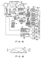
- the camera shake preventing circuit 32 detects a portion of an image of a subject formed on the film exposure surface 14 through the photographic optical lens 12 via a half mirror 34 to detect a difference between the subject images formed on the film exposure surface 14 and drives the actuator unit 30. More specifically, the camera shake preventing circuit 32 is arranged as shown in Fig. 2.
- the camera shake preventing circuit 32 is constituted by a drift detecting unit 36 for detecting a difference between images of a subject on an image formation surface and an actuator driving unit 38 for driving the actuator unit 30 in accordance with an output from the detecting unit 36.
- a portion of the subject image guided via the half mirror 34 is enlarged through an enlarging optical lens 40 and imaged on an imaging surface of a solid-state imaging device 42 having a high sensitivity and a high operation speed.
- This solid-state imaging device 42 is constituted by an AMI (amplifying MOS imager) and has functions of exposing an image of a subject within a time period shorter than an exposure time of the subject image by using the film and reading out an imaging signal at a high speed.
- An imaging device driver 44 drives the solid-state imaging device 42 at a high speed within a film exposure period of the subject image in synchronism with a shutter release operation, thereby repeatedly reading out the subject image.
- the subject image signal repeatedly read out at a high speed by the solid-state imaging device 42 is processed by a video processor 46 and sequentially digital-coded and fetched via an A/D converter 48.
- a frame memory 50 stores a first frame of the subject image signal fetched as described above in synchronism with the shutter release operation described above as a reference image signal for use in drift detection with respect to subject image signals fetched from the second frame.
- a two-dimensional correlation circuit 52 executes a two-dimensional correlation arithmetic operation between a subject image signal of the first frame stored in the frame memory 50 and those fetched from the second frame, thereby detecting differences between the image signals (frame images) as x and y displacements.
- This two-dimensional correlation arithmetic operation is performed by arbitrarily using various types of conventional arithmetic algorithms. That is, basically, projection components in the x and y directions of two frame images are respectively compared with each other, and a difference or drift is calculated as a displacement in each direction.
- a two-dimensional correlation circuit 52 executes a two-dimensional correlation arithmetic operation between the subject image signal of the first frame stored in the frame memory 50 and each subject image signal fetched from the second frame and detects a difference between the image signals (frame images) as x and y displacements.
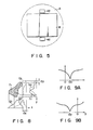
- This two-dimensional correlation arithmetic operation is performed by arbitrarily using various types of conventional arithmetic algorithms. That is, basically, projection components in x and y directions of two frame images f1 and f2 having a drift or difference with respect to time as shown in Fig. 8 are respectively compared with each other, and the difference is obtained as displacements in the two directions, thereby executing the two-dimensional correlation arithmetic operation.
- projection components are obtained by projecting the image signal in the y and x directions as indicated by g1 an h1, respectively. If the subject image moves as indicated by f2 as time passes, projection components g2 and h2 are obtained for the image f2. That is, if the image f1 moves in the x and y directions as indicated by f2, the projection components of the image also move from g1 and h1 to g2 and h2 in the x and y directions, respectively.
- the two-dimensional correlation circuit 52 calculates a correlation between the projection components in the two directions, thereby obtaining differences dx and dy between the subject images f1 and f2. For example, square sums of drifts between the respective projection components are obtained as correlation arithmetic output values as shown in Figs. 9A and 9B. By calculating values dx and dy for minimizing these correlation arithmetic output values, the values correspond to differences between the images of the subject in the x and y directions.
- the two-dimensional correlation circuit 52 executes the two-dimensional correlation arithmetic operation based on the arithmetic algorithm as described above to easily and rapidly detect a difference between images of a subject formed on an imaging surface of the solid-state imaging device 42 in accordance with the luminance component Y of the subject image signal. This difference or drift detection is performed each time a subject image signal is repeatedly read out at a high speed from the solid-state imaging device 42.
- Series of information of x and y displacements between images of a subject obtained by the two-dimensional correlation circuit 52 as described above are interpolated by interpolating circuits 54x and 54y to detect x and y displacements with a precision of a pixel unit or less, and the detected x and y displacements are supplied to actuator drivers 38x and 38y, respectively.
- the actuator drivers 38x and 38y respectively drive an x-direction actuator 30x and a y-direction actuator 30y constituting the actuator unit 30 to displace the photographic optical lens 12 in directions to correct the displacements in the x and y directions of the image of the subject.
- the driving system of the actuator unit 30 in this camera shake preventing circuit 32 is arranged to form a negative feedback loop with respect to a difference between images of a subject.
- the circuit 32 operates at a high speed in synchronism with a shutter release operation as shown in Fig. 3 and causes the solid-state imaging device 42 to repeatedly input an image of a subject during a film exposure period as a shutter open period.
- a difference between the subject image signal repeatedly imaged at a high speed by the solid-state imaging device 42 and the subject image signal of the first frame stored in the frame memory 50 immediately after the shutter release operation is performed is detected by a two-dimensional correlation arithmetic operation, and the actuator unit 30 is driven in accordance with the detected difference to displace the photographic optical lens 12 in a direction perpendicular to the optical axis of the lens 12.
- a compact device having, e.g., [8 x 8] pixels or [16 x 16] pixels is used as the solid-state imaging device 42, and a repetitive read period of an image signal is set to be as short as about 10 ⁇ sec.
- a shutter speed is comparatively high and a film exposure time is as short as about 250 ⁇ sec, a large number of subject image signals can be repeatedly obtained by the solid-state imaging device 42 within the film exposure period to execute the displacement control of the photographic optical lens 12 at a high speed with a high response speed by driving of the actuator unit 30, thereby effectively correcting a difference between images of a subject on the film exposure surface 14.
- an image of a subject is formed in an enlarged scale on the solid-state imaging device 42 through the enlarging optical lens 40, a difference or a drift can be detected with sufficiently high resolution even if the number of pixels constituting the device 42 is small.
- An enlargement magnification of the enlarging optical lens 40 may be determined in accordance with the resolution (pixel density) of the solid-state imaging device 42 and the resolution of a film.
- the displacement control of the photographic optical lens 12 with respect to a difference between images of a subject on the film exposure surface 14 caused by so-called camera shake can be performed at a high speed with good following characteristics.
- drift correction of the subject image is effectively executed on the film exposure surface 14 to perform high-resolution film exposure (photography) of the subject without so-called camera shake.
- a portion of an image of a subject to be formed on the film exposure surface 14 through the photographic optical lens 12 is split by using the half mirror 34 and imaged on the solid-state imaging device 42.
- the use of the half mirror 34 reduces a light amount of a subject image formed on the film exposure surface 14 and complicates the optical system.
- the solid-state imaging device 42 for drift detection may be located at a position outside a photography region of the film exposure surface 14 to omit the half mirror 34 (the second embodiment).
- an image circle A of the photographic optical lens 12 is set larger than a photography region B of the film exposure surface 14 so that an image of a subject is formed on a peripheral portion of the rectangular photography region B.
- exposure (photography) of an image of a subject is performed by using a film by masking the subject image, circularly formed within the range of the image circle A by the photographic optical lens 12, in accordance with the size of the film.
- the image of the subject is therefore formed on the peripheral portion of the film surface (photography region B).
- Figs. 5 In order to detect a difference between images of a subject by using the subject image formed outside the photography region B, as shown in Figs.
- the solid-state imaging element 42 is arranged outside, e.g., above or below the photographic region of the film exposure surface 14, and the subject image signal is repeatedly obtained at a high speed as described above within the film exposure period by using the solid-state imaging device 42.
- the arrangement can be simplified since no half mirror 34 is used, and the problem of reduction in light amount of an image of a subject reaching the film exposure surface 14 can be solved.
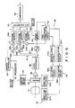
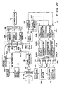
- Fig. 6 shows an arrangement of the third embodiment of the present invention in which the camera shake preventing circuit 32 described above is applied to an electronic camera.
- Fig. 6 the same reference numerals as in Fig. 2 denote the same parts.
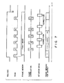
- Fig. 7 is a timing chart showing operation timings of the third embodiment.
- a subject image signal repeatedly read out at a high speed from a solid-state imaging device (imager) 42 which is driven at a high speed by an imaging device driver 44 is amplified to be a predetermined signal level via a preamplifier 56 and input to a video processor 46.
- This video processor 46 converts the subject image signal into a luminance signal Y and color difference signals (R - Y) and (B - Y) and outputs the signals.
- the luminance signal Y and the color difference signals (B - Y) and (R - Y) output from the video processor 46 in this manner are digital-coded by A/D converters 48a, 48b, and 48c, respectively.
- a frame memory 50 used in drift detection between images of a subject stores the first frame of the subject image signal (luminance signal Y) in synchronism with a shutter release operation.
- this subject image signal of the first frame is used as a reference image signal (reference subject image) for drift detection with respect to subject image signals obtained from the second frame.
- a two-dimensional correlation circuit 52 executes a two-dimensional correlation arithmetic operation between the subject image signal of the first frame stored in the frame memory 50 and each subject image signal fetched from the second frame and detects a difference between the image signals (frame images) as x and y displacements.
- This two-dimensional correlation arithmetic operation is performed by arbitrarily using various types of conventional arithmetic algorithms. That is, basically, projection components in x and y directions of two frame images f1 and f2 having a drift or difference with respect to time as shown in Fig. 8 are respectively compared with each other, and the difference is obtained as displacements in the two directions, thereby executing the two-dimensional correlation arithmetic operation.
- projection components are obtained by projecting the image signal in the y and x directions as indicated by g1 an h1, respectively. If the subject image moves as indicated by f2 as time passes, projection components g2 and h2 are obtained for the image f2. That is, if the image f1 moves in the x and y directions as indicated by f2, the projection components of the image also move from g1 and h1 to g2 and h2 in the x and y directions, respectively.
- the two-dimensional correlation circuit 52 calculates a correlation between the projection components in the two directions, thereby obtaining differences dx and dy between the subject images f1 and f2. For example, square sums of drifts between the respective projection components are obtained as correlation arithmetic output values as shown in Figs. 9A and 9B. By calculating values dx and dy for minimizing these correlation arithmetic output values, the values correspond to differences between the images of the subject in the x and y directions.
- the two-dimensional correlation circuit 52 executes the two-dimensional correlation arithmetic operation based on the arithmetic algorithm as described above to easily and rapidly detect a difference between images of a subject formed on an imaging surface of the solid-state imaging device 42 in accordance with the luminance component Y of the subject image signal. This difference or drift detection is performed each time a subject image signal is repeatedly read out at a high speed from the solid-state imaging device 42.
- Series of information of x and y displacements between images of a subject obtained by the two-dimensional correlation circuit 52 as described above are interpolated by interpolating circuits 54x and 54y to detect x and y displacements with a precision of a pixel unit or less, and the detected x and y displacements are supplied to actuator drivers 38x and 38y, respectively.
- the actuator drivers 38x and 38y drive an x-direction actuator 30x and a y-direction actuator 30y to displace a photographic optical lens 12 in directions to correct the displacements of the subject image in the x and y directions, respectively. While the photographic optical lens 12 is displaced by the x- and y-direction actuators 30x and 30y, the solid-state imaging device 42 inputs the image of the subject formed on the imaging surface of the device 42.
- the drive control system of the actuators 30x and 30y is arranged to form a negative feedback loop in order to displace the photographic optical lens 12 in a direction opposite to the direction of a difference between images of a subject.
- the solid-stage imaging device 42 is driven at a high speed as shown in Fig. 7 in synchronism with a shutter release operation to repeatedly input an image of a subject formed on its imaging surface within a photographing period determined under the control of a photometering system 18.
- the first frame of the subject image signal repeatedly input at a high speed by the solid-state imaging device 42 is stored in the frame memory 50.
- the two-dimensional correlation circuit 52 executes the two-dimensional correlation arithmetic operation between the subject image signal of the first frame obtained immediately after the shutter release operation and stored in the frame memory 50 and each subject image signal of the second and subsequent frames input thereafter, thereby detecting a difference or drift.
- the actuators 30x and 30y are driven in accordance with the detected drift to displace the photographic optical lens 12 in directions perpendicular to the optical axis of the lens 12.
- the high-speed driving of the solid-state imaging device 42 is performed such that an imaging operation and a read operation for an image signal are executed at a period of about 10 ⁇ sec.
- a large number of subject image signals can be repeatedly obtained by the solid-state imaging device 42 during the period to execute the displacement control of the photographic optical lens 12 at a high speed with a high response speed by the driving by the actuators 30x and 30y, thereby effectively correcting the difference between the subject images on the imaging surface of the solid-state imaging device 42.
- a subject image signal obtained by the solid-state imaging device 42 for rapidly and repeatedly inputting an image of a subject subjected to the drift correction on the imaging surface of the device 42 under the displacement control of the photographic optical lens 12 as described above is converted into a luminance signal Y and color difference signals (R - Y) and (B - Y) by the video processor 46, and the signals Y, (B - Y), and (R - Y) are digital-coded by the A/D converters 48a, 48b, and 48c, respectively.
- Three frame memories 58a, 58b, and 58c arranged in correspondence with these three signal components, for generating output image signals, fetch and store the signal components digital-coded by the A/D converters 48a, 48b, and 48c via adders 60a, 60b, and 60c, respectively.
- the adders 60a, 60b, and 60c read out the signal components stored in the frame memories 58a, 58b, and 58c, add newly input signal components to the readout signal components, and rewrite the obtained signal components in the frame memories 58a, 58b, and 58c, thereby obtaining accumulated values of the signal components in the frame memories 58a, 58b, and 58c, respectively.
- An accumulative arithmetic circuit using the frame memories 58a, 58b, and 58c and the adders 60a, 60b, and 60c is driven by a memory controller 62 in synchronism with the shutter release operation described above throughout the photographing operation period determined by the photometering system as described above.
- the electronic image input of a subject is repeatedly performed at a high speed by the solid-state imaging device 42, and an exposure time in each subject imaging is set to be shorter than that originally required. Therefore, a generation amount of a signal charge corresponding to the light amount of a subject in the solid-state imaging device 42 is increased in proportion to the exposure time, i.e., the generation amount of the signal charge is naturally decreased when the exposure time is set short. For this reason, the levels of the individual subject image signals repeatedly imaged at a high speed are decreased to be very low. In other words, an exposure amount with respect to a low-luminance component in a subject of each subject image signal becomes insufficient in correspondence with the short exposure time.
- the individual subject image signals repeatedly input at a high speed in order to perform the above difference or drift detection are repeatedly accumulated a plurality of times to increase the level of each image signal by the number of repeating times, thereby substantially widening the dynamic range of the signal to ensure a required signal level. For example, therefore, image signals are repeatedly read out n times within the photographing operation period determined under the control of the photometering system and accumulated. As a result, an accumulated image signal having a level (dynamic range) ⁇ n times that of each image signal is output.
- a random noise component of a dark current mixed in an image signal obtained by the solid-state imaging device 42 is ⁇ n times when an accumulation number is n .
- the luminance signal Y and the color difference signals (R - Y) and (B - Y) having enlarged signal levels as described above are read out from the frame memories 58a, 58b, and 58c, respectively, data-compressed by a compressor 66 via a parallel/serial (P/S) converter 64, and recorded in a predetermined recording medium (not shown).
- these signals are converted into a television signal such as an NTSC signal and used in image reproduction performed by a TV receiver or the like.
- a difference between images of a subject formed on the imaging surface of the solid-state imaging device 42 is effectively corrected to perform high-resolution photography without so-called image shake.
- differences between images of a subject in the x and y directions are calculated by the two-dimensional correlation arithmetic operation from subject image signals repeatedly obtained at a high speed by the solid-state imaging device 42.
- This calculation can be realized by a one-dimensional correlation arithmetic operation in each of the x and y drift directions.
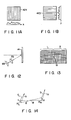
- Fig. 10 shows a schematic arrangement of a main part of a single-lens reflex camera according to the fourth embodiment of the present invention for this purpose.
- an image of a subject guided through an enlarging optical lens 40 is split by using another half mirror 34a and input by using a solid-stage imaging device 42x for x-direction drift detection and a solid-state imaging device 42y for y-direction drift detection.
- the solid-state imaging device 42x for x-direction drift detection is arranged to obtain an x-direction one-dimensional signal by accumulating image signals of an image of a subject formed on the device
- the solid-state imaging device 42y for y-direction drift detection is arranged to obtain a y-direction one-dimensional signal by accumulating image signals of a subject image formed on the device. That is, the solid-state imaging devices 42x and 42y directly obtain projection components in the x and y directions of an image of a subject formed on the elements and read out the projection components as one-dimensional image signal components in the x and y directions.
- the one-dimensional image signal components in the x and y directions read out by the solid-state imaging devices 42x and 42y are input to video processors 46x and 46y, subjected to predetermined signal processing, and digital-converted by A/D converters 48x and 48y, respectively.
- Line memories 50x and 50y store the first frames of the one-dimensionally compressed subject image signal components (one-dimensional projection components of subject image signals) obtained by the solid-state imaging devices 42x and 42y in synchronism with the shutter release operation described above as reference image signals for use in drift detection with respect to signal components of the subject image fetched from the second frame.
- One-dimensional correlation circuits 52x and 52y respectively execute one-dimensional correlation operations between the subject image signal component of the first frame and each subject image signal of the second and subsequent frames and detect differences or drifts in the x and y directions between the image signals (frame images).
- the drifts in the x and y directions obtained by the one-dimensional correlation circuits 52x and 52y in this manner are supplied to actuator drivers 38x and 38y to displace a photographic optical lens 12 in the x and y directions, respectively.
- the solid-state imaging devices 42x and 42y as shown in Figs. 11A and 11B are used to directly obtain projection components in the x and y directions of an image of a subject formed on the devices. Since one-dimensional signals are obtained as the projection components of the subject image by the solid-state imaging devices 42x and 42y as described above, the line memories 50x and 50y are used to store reference signals for drift detection in the x and y directions, respectively. As a result, the drift detection can be easily performed at a high speed by only executing one-dimensional arithmetic operations.
- the signals obtained by the solid-state imaging devices 42x and 42y will be described in more detail below. Assuming that a subject image f1 is formed on the solid-state imaging devices 42x and 42y as shown in Fig. 8, the devices 42x and 42y obtain one-dimensional projection components g1 and h1 obtained by projecting the image signal in the x and y directions, respectively. If the subject image is moved as indicated by f2 while the projection components g1 and h1 are stored in the line memories 50x and 50y, respectively, one-dimensional projection components g2 and h2 are obtained from the solid-state imaging devices 42x and 42y, respectively. That is, the projection components g2 and h2 are moved in the x and y directions respectively in correspondence with the drifts in the x and y directions.
- correlation arithmetic output values e.g., square sums of the drifts are obtained as shown in Figs. 9A and 9B, and positions dx and dy for minimizing the outputs are obtained as drifts in the x and y directions, respectively.
- the drift detection is easily performed at a high speed by the one-dimensional correlation arithmetic operations.
- the arithmetic circuit of the camera can be largely simplified.
- This arrangement of calculating a drift by the one-dimensional correlation arithmetic operation according to the fourth embodiment can be applied to an electronic camera.
- the exclusive solid-state imaging devices 42, 42x, and 42y are incorporated in order to detect a difference between images of a subject.
- Fig. 12 shows an arrangement of a photometering optical device (imaging device) 68 of a photometering system 18.
- the optical device (imaging device) 68 is incorporated in an exposure chamber (mirror chamber) of a camera main body (apparatus main body) 28 so as to receive an image of a subject reflected by a film exposure surface 14 through an imaging lens 70.
- the image formation surface of the optical device (imaging device) 68 is divided into two, left and right areas L and R by an optical center (optical axis) M as shown in Fig. 13, and a difference between images of a subject is independently detected in each of the areas L and R.
- a difference between subject images repeatedly obtained from each of the areas L and R is calculated by a correlation arithmetic operation as described above on the basis of the central position of each area, thereby obtaining differences dx L and dy L between the subject images in the area L and difference dx R and dy R therebetween in the area R.
- a single-lens reflex camera in which the above rotational difference correction is also performed will be described below.
- a characteristic feature of this sixth embodiment is that even if a rotational difference is detected between images of a subject and a photographic optical lens 12 is rotated about its optical axis M on the basis of the detected rotational difference, no change is produced in the subject image formed on a film exposure surface 14 through the photographic optical lens 12.
- a Dove prism 72 is incorporated in a photographic optical system as shown in Fig. 15 and rotationally displaced about its optical axis to perform correction for the rotational difference.
- the Dove prism 72 has a property of inverting and outputting an optical image incident on its prism surface.
- an output optical image can be inclined in accordance with the rotational displacement of the prism. Therefore, a rotational difference or drift can be optically corrected by rotationally displacing the Dove prism 72 in accordance with the rotational difference or drift.
- the Dove prism 72 When the Dove prism 72 is incorporated in a photographic optical system, however, an image of a subject formed on the film exposure surface is inevitably an inverted image obtained by so-called mirror surface reflection. In an actual arrangement, therefore, another Dove prism or a mirror may be inserted in the optical system to return the subject image formed on the film exposure surface to an erect image.
- the inverted image can be returned to an erect image by turning over and printing the film.
- the camera of the sixth embodiment capable of performing correction for also a rotational difference or drift is arranged as shown in Fig. 15.
- a subject image signal detected by using an optical device (imaging device) 68 as shown in Fig. 13 for photometry and drift detection is digital-converted by an A/D converter 48 and fetched.
- the fetched signal is supplied to a photometering system 18 and at the same time extracted as signals of areas L and R describe above via an area switch 74.
- the first frames of the image signals in the areas L and R are stored in frame memories 50L and 50R, respectively.
- two-dimensional correlation circuits 52L and 52R execute correlation arithmetic operations between the stored signals and signals of the areas L and R repeatedly read out at a high speed from the optical device (imaging device) 68.
- a difference f L (dx L , dy L ) and a difference f R (dx R , dy R ) in the areas L and R are respectively calculated.
- the subtracters 76a and 76b respectively calculate: (dx L - dx R )/2 , (dy L - dy R )/2 and a rotational amount detector 78 calculates a rotational difference or drift
- ⁇ (dx ⁇ L ⁇ - dx ⁇ R ⁇ )2 + (dy ⁇ L ⁇ - dy ⁇ R ⁇ )2 ⁇
- R L is a vector amount while the rotational difference or drift is a scalar amount
- a ⁇ actuator 308 is driven in accordance with the rotational drift
- the adders 76c and 76d respectively calculate: (dx L + dx R )/2, (dy L + dy R )/2 in accordance with the above respective differences, thereby calculating translation amount components in the x and y directions.
- An xy-actuator driver 38 is activated by these signals to drive an xy actuator 30xy, thereby displacing the photographic optical lens 12 in the x and y directions to correct the translation difference between the images of the subject.
- This rotational drift correction can be naturally applied to an electronic camera.
- a rotational drift is corrected by using the Dove prism 72, and a translation drift is optically corrected by displacing the photographic optical lens 12 in the x and y directions.
- Rotational and translation drifts can be corrected by rotating and translating a fiber bundle.
- the film exposure surface 14 itself can be displaced to perform the drift correction.
- the entire imaging system up to the film exposure surface 14 including the photographic optical lens 12 is incorporated in an inner housing member 88, and the inner housing member 82 is supported by voice coils 86 so as to be movable with respect to an outer housing member 84 as a camera apparatus main body 28 (the seventh embodiment).
- the voice coils 86 are driven in accordance with a drift or difference between images of a subject to displace an optical positional relationship of the entire imaging system with respect to the subject, thereby correcting the drift as a whole.
- the entire film exposure surface 14 including a film is incorporated in an inner housing member 88, and the inner housing member 88 is supported by voice coils 86 so as to be movable with respect to an outer housing member 84 as a camera apparatus main body 28 (the eighth embodiment).
- the voice coils 86 are driven in accordance with a drift or a difference between images of a subject to displace an optical positional relationship of the film exposure surface 14 with respect to the subject, thereby correcting the drift.
- a photographic optical lens 12 is incorporated in the outer housing member 84 as the camera apparatus main body 28.
- each of the embodiments shown in Figs. 17 and 18 is realized by supporting a film storage portion 90 (inner housing member 88) having at least the film exposure surface 14 by four voice coils 86 arranged to be symmetrical in vertical and horizontal directions so as to be movable in four directions with respect to the housing member 84 indicated by a dotted line as shown in Fig. 19, thereby obtaining a double housing structure.
- a film storage portion 90 inner housing member 88
- four voice coils 86 arranged to be symmetrical in vertical and horizontal directions so as to be movable in four directions with respect to the housing member 84 indicated by a dotted line as shown in Fig. 19, thereby obtaining a double housing structure.
- the inner housing member 88 is supported by the four voice coils 86 with respect to the outer housing member 84 such that, as shown in Fig. 20, support directions are set toward upper and lower support points P and Q off-centered from the optical axis M. That is, support directions of the voice coils 86UL and 86UR with respect to the inner housing member 88 are directed toward the support point Q set below the optical axis M, and support directions of the lower voice coils 86DL and 86DR with respect to the inner housing member 88 are directed toward the support point P set above the optical axis M.
- each of the voice coils 86UL, 86UR, 86DL, and 86DR is mounted on the outer housing member 84 via a rotary joint 92 so that an expandable shaft of each voice coil 86 is not twisted due to a displacement of the inner housing member 88.
- a rightward moving vector is generated as shown in Fig. 21A, and the inner housing member 88 is displaced to the right with respect to the outer housing member 84.
- a leftward moving vector is generated to displace the inner housing member 88 to the left with respect to the outer housing member 84.
- the inner housing member 88 is displaced vertically or horizontally with respect to the outer housing member 84 by complimentarily expanding/ contracting the voice coils 86UL, 86UR, 86DL, and 86DR constituting upper and lower pairs or right and left pairs.
- the vertical and horizontal displacements are synthesized to displace the inner housing member 88 obliquely with respect to the outer housing member 84.
- the voice coils 86UL, 86UR, 86DL, and 86DR are selectively expanded/contracted to rotate the inner housing member 88, thereby correcting a rotational drift or difference between images of a subject formed on the film exposure surface 14.
- this rotational drift correction is combined with the control of translation displacement described above, the rotational drift and the translation drift of the subject images can be effectively corrected.
- the optical axis M itself of the photographic optical system can be inclined by independently controlling a displacement on the photographic optical lens 12 side and that on the film exposure surface 14 side.
- a displacement control method is adopted, therefore, not only the vertical or horizontal drift and the rotational drift with respect to the optical axis M of an image of a subject can be corrected, but also a drift with respect to yawing or pitching can be effectively corrected.
- the voice coils as described in the above seventh and eighth embodiments can be naturally applied to an electronic camera.
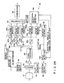
- Fig. 22 shows an arrangement of the ninth embodiment of the present invention capable of correcting a rotational drift.
- a characteristic feature of the present invention is that a solid-state imaging device 42 is supported via an xy ⁇ actuator 30 which can be displaced in the x and y directions and can be rotationally displaced about an optical axis M of the device 42 and a control system is arranged to control an actuator driver 38 to displace a photographic optical lens 12 in the and ⁇ directions.
- two, left and right areas L and R are set by the optical center (optical axis) M in the imaging surface of the solid-state imaging device 42 as shown in Figs. 23A and 23B, a drift or a difference between images of a subject is independently detected in each of the areas L and R, and translation displacements in the x and y directions and a rotational displacement ⁇ about the optical axis M of the entire subject image are calculated in accordance with the detected drifts in the areas L and R.
- the drifts in the x and y directions between the subject images can be obtained in the same manner as described above with reference to Fig. 4 to enable correction of the drifts.
- correction for the rotational drift is performed in accordance with the rotational drift of the subject images.
- the drift correction for the subject images can be executed more precisely.
- a luminance component Y obtained by digital-converting a subject image signal repeatedly input at a high speed by the solid-state imaging device 42 is supplied to an area switch 74 to extract subject image signals (partial image signals) of the areas L and R.
- the first frames of the image signals of the areas L and R are stored in frame memories 50L and 50R, respectively, and two-dimensional correlation circuits 52L and 52R respectively execute correlation arithmetic operations between the stored signals and signals of the areas L and R repeatedly read out at a high speed by the solid-state imaging device 42. Drifts or differences (vectors) and of the areas L and R are respectively calculated by the correlation arithmetic operations performed by the two-dimensional correlation circuits 52L and 52R.
- the subtracters 76a and 76b respectively calculate: (dx R - dx L )/2 , (dy R - dy L )/2 . These values are supplied to a rotational amount detector 78.
- the detector 78 executes the following arithmetic operation to calculate a rotational drift
- ⁇ (dx ⁇ R ⁇ - dx ⁇ L ⁇ )2 + (dy ⁇ R ⁇ - dy ⁇ L ⁇ )2 ⁇ .
- R L is a vector amount while the rotational drift is a scalar amount,
- the actuator driver 38 is controlled in accordance with this rotational drift
- the xy ⁇ actuator 30 rotationally displaces the solid-state imaging device 42 about the optical axis of the device, thereby correcting the rotational drift.
- the adders 76c and 76d respectively calculate: (dx L + dx R )/2, (dy L + dy R )/2 in accordance with the above drifts, thereby calculating translation amount components in the x and y directions.
- the actuator driver 38 is activated in accordance with the calculated drifts to drive the xy ⁇ actuator 30, thereby displacing the solid-state imaging device 42 in the x and y directions to correct the translation drift between the images of the subject.
- control system Since the control system is arranged as described above, not only drifts in the x and y directions between images of a subject formed on the imaging surface of the solid-state imaging device 42 but also a rotational drift between the images can be effectively corrected to enable high-resolution photography without so-called image shake.
- the translation amount and the rotational moving amount of the entire image are calculated in accordance with drift detection results of the two, left and right areas L and R about the optical axis M in the imaging surface of the solid-state imaging device 42.
- the displacements in the x and y directions and the rotational displacement can be calculated in accordance with only one arbitrary point of the image.
- a control system is arranged, e.g., as shown in Fig. 24 (the tenth embodiment). That is, two frame memories 50a and 50b are arranged to store a luminance signal Y of a subject image signal input by a solid-state imaging device 42.
- the first frame memory 50a stores an image signal of the first frame
- the second frame memory 50b sequentially stores image signals from the second frame.
- An image signal in an arbitrary position is read out from the second frame memory 50b under the control of an address controller 96, and a rotational angle detector 98 calculates a rotational angle 8 for maximizing a correlation with respect to the image signal stored in the first frame memory 50a and a corresponding correlation value ⁇ ( ⁇ ).
- the rotational angle detector 98 executes a correlation arithmetic operation between the image signal stored in the first frame memory 50a and an image signal in an arbitrary position (x, y) read out from the address-controlled second frame memory 50b, and a peak detector 100 monitors the rotational angle ⁇ and the correlation value ⁇ ( ⁇ ) output from the rotational angle detector 98 to obtain the rotational angle ⁇ as a rotational drift corresponding to the maximum correlation value ⁇ ( ⁇ ).
- the position (x, y) of the image signal read out from the second frame memory 50b is obtained as a translation amount in the x and y directions.
- An actuator driver 38 is activated in accordance with the rotational drift ⁇ and the drifts in the x and y directions calculated as described above to drive an xy ⁇ actuator 30, thereby displacing the solid-state paging device 42 to correct the drifts.
- an angle ⁇ for maximizing a correlation output between the images represented by: ⁇ ( ⁇ ) f1'( ⁇ )*f2'( ⁇ ) is the angle ⁇ 0.
- a solid-state imaging device having a pixel arrangement (imaging array structure) capable of adding image signals in the radial direction as shown in Fig. 25 and outputting the sum signal may be used.
- the above rotational angle detection can also be realized by applying two-dimensional Mellin transform as described in the following reference: [Casasent D and D. Psaltis (1976), "Position, Rotation, and Scale Invariant Optical Correction", Appl. Opt. 15, 1705 - 1799].
- a method of detecting a drift between images of a subject or a method of correcting the detected drift can be performed by arbitrarily combining the methods described in the above embodiments.
- the function of displacing the photographic optical lens 12 can be incorporated in either the photographic lens or a lens mount portion or the like of a main body.
- the solid-state imaging device 42 for detecting a drift between images of a subject may be either incorporated in a photographic lens or fixed in a main body.
- a member to be mounted on the outer housing member such as a film wind mechanism is naturally connected to a member to be incorporated in the inner housing member 88 via a flexible member.
- an electronically input subject image signal can be electronically subjected to drift correction.
- a random-access imaging device can be used to selectively read out partial images in the areas L and R described above.
- a nondestructive solid-state imaging device is used to accumulate imaging signals of its own, the above-mentioned accumulative addition processing for image signals executed by adders and frame memories need not be performed.
- an effective camera shake preventing circuit can be realized by using a drift between images of a subject on the imaging surface detected by the drift detecting unit 36.
- the detection result obtained by the drift detecting unit 36 can be used in various applications other than the above camera shake preventing circuit.
- a technique of panning a camera to continuously image a subject and combining a plurality of still pictures to obtain a panorama photograph is available.
- a camera main body is generally mounted on a tripod to perform a shutter release operation while the direction of an imaging field of the camera is horizontally panned in units of predetermined angles, thereby sequentially recording images of a subject in the respective fields.
- Such panorama photography therefore, can be effectively performed by using an output from the drift detecting unit 36 as described above.
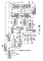
- Fig. 26 shows an arrangement of an electronic still camera as a camera apparatus according to the eleventh embodiment of the present invention in which a drift detecting unit is used in panorama photography.
- an imaging optical lens 12 is moved along its optical axis direction by a focusing mechanism (not shown) to perform focusing with respect to an image of a subject formed on the imaging surface of a solid-state imaging device 42.
- a half mirror 20 arranged in an optical path between the imaging optical lens 12 and the solid-state imaging device 42 guides a portion of the subject image formed on the imaging surface of the solid-state imaging device 42 by the imaging optical lens 12 to a finder system (not shown).
- the imaging optical lens 12 is supported by a camera main body so as to be displaced in the vertical direction (the y direction) of the imaging surface by a y-direction actuator 30y.
- the solid-state imaging device 42 is supported to be rotationally displaceable about its optical axis by a rotary actuator 30 ⁇ .
- the actuators 30y and 30 ⁇ are driven by actuator drivers 38y and 38 ⁇ to cause a vertical displacement of the imaging optical lens 12 and a rotational displacement of the solid-state imaging device 42, respectively.
- an optical positional relationship of an imaging optical system with respect to a subject is displaced to perform correction for a drift or a difference between images of the subject formed on the imaging surface of the solid-state imaging device 42 as will be described later.
- the solid-state imaging device 42 inputs an image of a subject at a predetermined period such as a TV rate, and an imaging signal (subject image signal) is supplied to a video processor 46.
- the processor 46 performs emphasis correction or the like for the input subject image signal and separately outputs the corrected signal as a luminance signal component Y and two color difference signal components (R - Y) and (B - Y).
- the signal components Y, (B - Y), and (R - Y) separated by the video processor 46 are digital-coded by A/D converters 48a, 48b, and 48c, respectively, and converted into a single time-serial signal (digital image signal) by a P/S converter 64.
- This signal is subjected to predetermined data compression processing by a data compressor 66 and recorded in an image memory 102.
- the recording of a digital image signal into the image memory 102 is performed independently of the imaging of a subject image performed by the solid-state imaging device 42 in response to an imaging command generated upon a shutter release operation or an imaging command generated by an image position detector (to be described later). That is, only when an imaging command is supplied, the recording of a subject image signal of a certain scene currently supplied to the image memory 102 is performed.
- the obtained subject image signal is recorded in the image memory 102.
- images of a subject are recorded in the image memory 102 in an order of an imaging command given for the signal while the recorded images are managed in accordance with management information such as a frame number.
- a characteristic feature of the apparatus of this embodiment is as follows. That is, when panorama photography is to be performed by horizontally panning the camera, in accordance with a panorama instruction generated in response to a switching operation of a photographic mode switch (not shown), a drift or a difference between images of a subject is detected by using a luminance signal component Y extracted by the video processor 46 from the subject image input at a predetermined period by the solid-state imaging device 42 as described above, and an image drift in the vertical direction (the y direction) of a picture and a rotational drift are corrected in accordance with the detected drift. If a predetermined amount of an image drift is detected in the horizontal direction (the x direction) of a picture, it is determined that the imaging optical system is panned by a predetermined angle, and the imaging command is automatically supplied to the image memory 102.
- a signal input switch 104 of a displacement detecting system is switched on to supply the luminance signal component Y of the subject image continuously input at a predetermined period to an area selector 106.
- the area selector 106 selects one of two partial areas A and B symmetrically disposed with respect to the optical axis M.
- Two-dimensional correlation circuits 52a and 52b execute two-dimensional correlation arithmetic operations between the images of the partial areas A and B written in the frame memories 50a and 50b and a subject image signal input at a predetermined period thereafter, thereby obtaining displacement positions of the images in the areas A and B, respectively.
- the frame memories 50a and 50b are rewritten at a predetermined period to be used in a correlation arithmetic operation between the latest two frames.
- the two-dimensional correlation circuits 52a and 52b constantly execute the two-dimensional correlation arithmetic operations between latest continuous subject signals, i.e., a current subject signal and the subject signal of the immediately preceding frame stored in the frame memories 50a and 50b and detect drift between the image signals (frame images) as x and y displacements, respectively.
- a rotational amount detector 78 calculates a rotational drift in accordance with x-displacement information of the subject image in the partial areas A and B respectively obtained by the two-dimensional correlation circuits 52a and 52b.
- a y-direction moving amount detector 108 calculates a drift in the y direction in accordance with y-displacement information of the subject image in the areas A and B and information of the rotational drift obtained by the rotational amount detector 78.
- an image position detector 110 determines in accordance with the x- and y-displacement information of the subject image in the areas A and B that the areas A" and B" move to A' and B' as shown in Fig. 27, it generates an imaging command, Recording of the next subject image signal is performed in accordance with the imaging signal.
- the y-direction moving amount and the rotational drift calculated as described above are supplied to the actuator drivers 38y and 38 ⁇ , respectively.
- the actuator driver 38y drives the y-direction actuator 30y to displace the imaging optical lens 12 in a direction to correct the displacement in the y direction of the subject image.
- the actuator driver 38 ⁇ drives the actuator 30 ⁇ to rotationally displace the solid-state imaging device 42 in a direction to correct a rotational drift of the image.
- the above rotational moving vector components R A and R B are generated due to, e.g., an inclination of the camera caused by the shutter release operation.
- correction for a rotational drift is performed in accordance with the rotational drift between the subject images.
- the drift correction for the subject image can be performed with higher precision.
- a luminance component Y obtained by digital-converting a subject image signal repeatedly input by the solid-state imaging device 42 is supplied to the area selector 106 to extract subject image signals (partial image signals) of the areas A and B described above.
- the two-dimensional correlation circuits 52a and 52b respectively execute correlation arithmetic operations between image signals of two continuous frames in the areas A and B, thereby obtaining the drifts (vectors) f A (dx A , dy A ) and f B (dx B , dy B ) between the two continuous frames in the areas A and B.
- the drifts f A (dx A , dy A ) and f B (dX B , dy B ) respectively calculated from the subject image signal in the areas A and B repeatedly obtained at a high speed as described above are input to the rotational amount detector 78 and the y-direction moving amount detector 108, thereby calculating a rotational drift and a translation drift.
- the actuator driver 38y is activated in accordance with the drift in the y direction described above to drive the actuator 30y, thereby displacing the imaging optical lens 12 in the y direction to correct the translation drift in the y direction between the images of the subject.
- control system Since the control system is arranged as described above, not only a drift in the y direction but also a rotational drift between images of a subject formed on the imaging surface of the solid-state imaging device 42 can be effectively corrected to execute high-resolution photography without so-called image shake.
- the image position detector 110 checks in accordance with an accumulated drift in the x direction calculated by the above drift detection whether an image of a subject formed by the solid-state imaging device 42 is displaced by a predetermined amount in the horizontal direction (the x direction). More specifically, the detector 110 checks whether images in the partial areas A" and B" shown in Fig. 27 move to the left ends A' and B' in the screen.
- the image position detector 110 When the image position detector 110 detects that an image of a subject moves by a distance slightly shorter than the screen width, it generates an imaging command to the image memory 102. In response to this imaging command, the next subject image is written in the image memory 102. In synchronism with the write operation for the subject image into the image memory 102, image signals of the partial areas A and B of the subject image are written in the frame memories 50a and 50b. The above drift detection is performed on the basis of these images of the areas A and B written in the frame memories 50a and 50b.
- an image of a subject input at a predetermined period by the solid-state imaging device 42 is recorded in the image memory 102 on the basis of a timing at which a panorama instruction is given to generate an imaging command, and a drift detection is performed between the subject images in accordance with a specific portion of the recorded images. If a drift is detected in a direction other than the panning direction, the imaging optical system is displaced in a direction to correct the drift to execute the drift correction. In addition, when a drift in the panning direction reaches a predetermined amount, it is determined that the camera is panned by the predetermined amount, and an imaging command is automatically generated.
- the image recording is executed when images in the partial areas A" and B" on the right side of the imaging screen move to the left areas A' and B', a portion corresponding to the image width the partial area is double-recorded.
- a drift between the images can be easily corrected by using the above double-recorded image portion, and the combining processing can be effectively performed.
- an image drift which cannot be corrected by the displacement control of the imaging optical system described above can be corrected by using the above double-recorded image portion to perform the combining processing.
- the present invention is not limited to the above embodiment.
- the rotational drift correction can be omitted.
- the solid-state imaging device 42 can be vertically displaced, or a rotational drift can be optically corrected by using a prism or the like.
- a photographic focal length, an in-focus position, an exposure amount, and the like are preferably maintained constant. As a result, the precision of a correlation arithmetic operation with respect to an image can be easily increased.
- the two partial areas are set to perform image drift detection in the above embodiment, only one partial area can be set.
- images of the partial areas are fetched in the frame memories, and drift detection is performed in accordance with the fetched partial images.
- the drift detection can be performed on the basis of one image stored in an image memory by checking a portion of the image stored in the image memory to which an image portion of the partial area A of a sequentially input image corresponds by a two-dimensional correlation arithmetic operation.
- the camera apparatus Since the camera apparatus according to the present invention has the drift correction function as described above, a user can easily perform panorama photography by holding the camera. Especially when a user uses a tripod, panorama photography can be performed at a high speed since he or she need only pan the camera. Furthermore, the camera can be mounted on a moving body (an automobile or train) to panoramically image a moving subject through a window.
Landscapes
- Engineering & Computer Science (AREA)
- Multimedia (AREA)
- Signal Processing (AREA)
- Physics & Mathematics (AREA)
- General Physics & Mathematics (AREA)
- Studio Devices (AREA)
- Adjustment Of Camera Lenses (AREA)
Applications Claiming Priority (6)
| Application Number | Priority Date | Filing Date | Title |
|---|---|---|---|
| JP343615/89 | 1989-12-28 | ||
| JP343614/89 | 1989-12-28 | ||
| JP01343615A JP3109808B2 (ja) | 1989-12-28 | 1989-12-28 | 電子カメラ装置 |
| JP1343614A JP3024979B2 (ja) | 1989-12-28 | 1989-12-28 | カメラ装置 |
| JP18928/90 | 1990-01-31 | ||
| JP02018928A JP3105515B2 (ja) | 1990-01-31 | 1990-01-31 | 電子カメラ |
Publications (2)
| Publication Number | Publication Date |
|---|---|
| EP0435319A1 true EP0435319A1 (fr) | 1991-07-03 |
| EP0435319B1 EP0435319B1 (fr) | 1997-03-12 |
Family
ID=27282417
Family Applications (1)
| Application Number | Title | Priority Date | Filing Date |
|---|---|---|---|
| EP90125675A Expired - Lifetime EP0435319B1 (fr) | 1989-12-28 | 1990-12-28 | Caméra ayant un détecteur de dérive |
Country Status (3)
| Country | Link |
|---|---|
| US (1) | US5416557A (fr) |
| EP (1) | EP0435319B1 (fr) |
| DE (1) | DE69030165T2 (fr) |
Cited By (8)
| Publication number | Priority date | Publication date | Assignee | Title |
|---|---|---|---|---|
| WO1993006689A1 (fr) * | 1991-09-27 | 1993-04-01 | Grundig E.M.V. Elektro-Mechanische Versuchsanstalt Max Grundig Holländ. Stiftung & Co Kg | Evaluation de mouvement dans des scenes enregistrees par des cameras video |
| EP0556666A1 (fr) * | 1992-02-06 | 1993-08-25 | Nikon Corporation | Dispositif pour la prise de vues pendant un mouvement pivotant d'un appareil photographique |
| EP0734155A1 (fr) * | 1995-03-20 | 1996-09-25 | SHARP Corporation | Dispositif de détection de déplacement de trame, appareil de prises de vues et d'enregistrement vidéo avec mode panoramique |
| EP0838947A1 (fr) * | 1992-10-09 | 1998-04-29 | Sony Corporation | Génération et enregistrement d'images |
| EP0884897A1 (fr) * | 1997-06-11 | 1998-12-16 | Hitachi, Ltd. | Caméra panoramique numérique |
| WO2000035188A1 (fr) * | 1998-12-08 | 2000-06-15 | Turgut Kaya | Camera numerique |
| EP0926888A3 (fr) * | 1997-12-25 | 2002-02-13 | Matsushita Electric Industrial Co., Ltd. | Dispositif de prise de vues |
| US6393216B1 (en) | 1992-09-28 | 2002-05-21 | Minolta Co., Ltd. | Camera system including a monitor device |
Families Citing this family (14)
| Publication number | Priority date | Publication date | Assignee | Title |
|---|---|---|---|---|
| JP3227173B2 (ja) * | 1991-06-24 | 2001-11-12 | キヤノン株式会社 | 撮像装置及びその方法 |
| JPH0643365A (ja) * | 1992-07-24 | 1994-02-18 | Canon Inc | 観察用光学機器 |
| US5666563A (en) * | 1993-07-12 | 1997-09-09 | Nikon Corporation | Camera having hand tremor correction mechanism |
| JPH09189932A (ja) * | 1996-01-10 | 1997-07-22 | Olympus Optical Co Ltd | カメラの手ブレ検出装置 |
| US6785426B1 (en) * | 1999-12-01 | 2004-08-31 | Canon Kabushiki Kaisha | Imaging apparatus, control method for imaging apparatus, and computer program product for providing control program for imaging apparatus |
| JP3770271B2 (ja) * | 2002-12-26 | 2006-04-26 | 三菱電機株式会社 | 画像処理装置 |
| JP3867691B2 (ja) * | 2003-07-15 | 2007-01-10 | ソニー株式会社 | 撮像装置 |
| JP4389749B2 (ja) * | 2004-10-15 | 2009-12-24 | 株式会社ニコン | パンニング撮影可能なカメラおよび動画像編集用プログラム |
| JP2006235071A (ja) * | 2005-02-23 | 2006-09-07 | Fuji Photo Film Co Ltd | 撮像装置 |
| US7598979B2 (en) * | 2005-09-21 | 2009-10-06 | Aptina Imaging Corporation | Imaging device with blur reduction system including a primary array and at least one navigation array |
| JP5003008B2 (ja) * | 2006-04-17 | 2012-08-15 | コニカミノルタアドバンストレイヤー株式会社 | 手振れ補正装置、レンズユニットおよび撮像装置 |
| US7660687B1 (en) * | 2006-05-25 | 2010-02-09 | Kla-Tencor Corporation | Robust measurement of parameters |
| JP4772009B2 (ja) * | 2007-08-07 | 2011-09-14 | 三洋電機株式会社 | ディジタルカメラ |
| JP5493942B2 (ja) | 2009-12-15 | 2014-05-14 | ソニー株式会社 | 撮像装置と撮像方法 |
Citations (3)
| Publication number | Priority date | Publication date | Assignee | Title |
|---|---|---|---|---|
| US4218119A (en) * | 1977-08-29 | 1980-08-19 | Canon, Inc. | System for controlling the exposure in a camera |
| US4492452A (en) * | 1982-04-07 | 1985-01-08 | Tokyo Shibaura Denki Kabushiki Kaisha | Picture blur-alarm device for a camera |
| EP0149365A2 (fr) * | 1983-12-29 | 1985-07-24 | Matsushita Electric Industrial Co., Ltd. | Dispositif de prise de vues |
Family Cites Families (8)
| Publication number | Priority date | Publication date | Assignee | Title |
|---|---|---|---|---|
| US3825748A (en) * | 1973-09-24 | 1974-07-23 | Photo Control Corp | Camera aiming structure |
| US4709138A (en) * | 1984-02-09 | 1987-11-24 | Canon Kabushiki Kaisha | Apparatus for detecting shake of image of object |
| US4673276A (en) * | 1984-02-24 | 1987-06-16 | Canon Kabushiki Kaisha | Blur detecting device for a camera |
| US4615590A (en) * | 1984-07-17 | 1986-10-07 | Schwem Instruments | Optically stabilized camera lens system |
| US4788596A (en) * | 1985-04-26 | 1988-11-29 | Canon Kabushiki Kaisha | Image stabilizing device |
| JPH07117676B2 (ja) * | 1985-08-26 | 1995-12-18 | キヤノン株式会社 | 防振系の制御装置 |
| US4780739A (en) * | 1985-09-06 | 1988-10-25 | Canon Kabushiki Kaisha | Anti-vibration imaging device |
| US5012270A (en) * | 1988-03-10 | 1991-04-30 | Canon Kabushiki Kaisha | Image shake detecting device |
-
1990
- 1990-12-28 EP EP90125675A patent/EP0435319B1/fr not_active Expired - Lifetime
- 1990-12-28 DE DE69030165T patent/DE69030165T2/de not_active Expired - Fee Related
-
1994
- 1994-03-08 US US08/208,051 patent/US5416557A/en not_active Expired - Lifetime
Patent Citations (3)
| Publication number | Priority date | Publication date | Assignee | Title |
|---|---|---|---|---|
| US4218119A (en) * | 1977-08-29 | 1980-08-19 | Canon, Inc. | System for controlling the exposure in a camera |
| US4492452A (en) * | 1982-04-07 | 1985-01-08 | Tokyo Shibaura Denki Kabushiki Kaisha | Picture blur-alarm device for a camera |
| EP0149365A2 (fr) * | 1983-12-29 | 1985-07-24 | Matsushita Electric Industrial Co., Ltd. | Dispositif de prise de vues |
Cited By (10)
| Publication number | Priority date | Publication date | Assignee | Title |
|---|---|---|---|---|
| WO1993006689A1 (fr) * | 1991-09-27 | 1993-04-01 | Grundig E.M.V. Elektro-Mechanische Versuchsanstalt Max Grundig Holländ. Stiftung & Co Kg | Evaluation de mouvement dans des scenes enregistrees par des cameras video |
| EP0556666A1 (fr) * | 1992-02-06 | 1993-08-25 | Nikon Corporation | Dispositif pour la prise de vues pendant un mouvement pivotant d'un appareil photographique |
| US5761545A (en) * | 1992-02-06 | 1998-06-02 | Nikon Corporation | Pan shot device for a camera |
| US6393216B1 (en) | 1992-09-28 | 2002-05-21 | Minolta Co., Ltd. | Camera system including a monitor device |
| EP0838947A1 (fr) * | 1992-10-09 | 1998-04-29 | Sony Corporation | Génération et enregistrement d'images |
| EP0878963A1 (fr) * | 1992-10-09 | 1998-11-18 | Sony Corporation | Génération et enregistrement d'images |
| EP0734155A1 (fr) * | 1995-03-20 | 1996-09-25 | SHARP Corporation | Dispositif de détection de déplacement de trame, appareil de prises de vues et d'enregistrement vidéo avec mode panoramique |
| EP0884897A1 (fr) * | 1997-06-11 | 1998-12-16 | Hitachi, Ltd. | Caméra panoramique numérique |
| EP0926888A3 (fr) * | 1997-12-25 | 2002-02-13 | Matsushita Electric Industrial Co., Ltd. | Dispositif de prise de vues |
| WO2000035188A1 (fr) * | 1998-12-08 | 2000-06-15 | Turgut Kaya | Camera numerique |
Also Published As
| Publication number | Publication date |
|---|---|
| US5416557A (en) | 1995-05-16 |
| DE69030165T2 (de) | 1997-10-16 |
| DE69030165D1 (de) | 1997-04-17 |
| EP0435319B1 (fr) | 1997-03-12 |
Similar Documents
| Publication | Publication Date | Title |
|---|---|---|
| US5416557A (en) | Camera apparatus having drift detecting unit | |
| USRE48552E1 (en) | Method and system for image construction using multiple exposures | |
| US7432953B2 (en) | Image-taking apparatus detecting vibration and correcting image blurring | |
| JP4522207B2 (ja) | カメラシステム、カメラ本体及び交換レンズ | |
| US6947074B2 (en) | Image pickup apparatus | |
| JP4378272B2 (ja) | 撮影装置 | |
| US5990942A (en) | Photographing apparatus using image information for blurring correction | |
| JP2006050457A (ja) | 撮像装置 | |
| JP4567313B2 (ja) | カメラ | |
| JP2004221992A (ja) | 撮影装置およびプログラム | |
| US7598979B2 (en) | Imaging device with blur reduction system including a primary array and at least one navigation array | |
| JPH1188754A (ja) | 画像信号撮像および記録装置および方法 | |
| JPH0943507A (ja) | 電子スチルカメラおよびそのフォーカス制御方法 | |
| WO2019056340A1 (fr) | Système de prise de vues ayant un cadre de prise de vues agrandi et procédé de commande associé | |
| JP2006345317A (ja) | 撮像装置及びその制御方法及びプログラム及び記憶媒体 | |
| JP3551932B2 (ja) | 測距装置及びそれを用いた撮像装置 | |
| JP5038448B2 (ja) | カメラ | |
| JP2007043584A (ja) | 撮像装置およびその制御方法 | |
| JP3024979B2 (ja) | カメラ装置 | |
| JP3109808B2 (ja) | 電子カメラ装置 | |
| JP2020043419A (ja) | 撮像装置及びその制御方法、並びにプログラム | |
| JP2004056222A (ja) | 撮像装置、撮像装置の制御方法、プログラム、及びコンピュータ読み取り可能な記憶媒体 | |
| JP2003198923A (ja) | 撮像装置およびその撮像方法 | |
| JPH10191147A (ja) | 撮像装置及び撮像方法 | |
| JPH04336776A (ja) | カメラシステム |
Legal Events
| Date | Code | Title | Description |
|---|---|---|---|
| PUAI | Public reference made under article 153(3) epc to a published international application that has entered the european phase |
Free format text: ORIGINAL CODE: 0009012 |
|
| AK | Designated contracting states |
Kind code of ref document: A1 Designated state(s): DE |
|
| 17P | Request for examination filed |
Effective date: 19910527 |
|
| 17Q | First examination report despatched |
Effective date: 19940329 |
|
| GRAG | Despatch of communication of intention to grant |
Free format text: ORIGINAL CODE: EPIDOS AGRA |
|
| GRAH | Despatch of communication of intention to grant a patent |
Free format text: ORIGINAL CODE: EPIDOS IGRA |
|
| GRAH | Despatch of communication of intention to grant a patent |
Free format text: ORIGINAL CODE: EPIDOS IGRA |
|
| GRAA | (expected) grant |
Free format text: ORIGINAL CODE: 0009210 |
|
| AK | Designated contracting states |
Kind code of ref document: B1 Designated state(s): DE |
|
| REF | Corresponds to: |
Ref document number: 69030165 Country of ref document: DE Date of ref document: 19970417 |
|
| PLBE | No opposition filed within time limit |
Free format text: ORIGINAL CODE: 0009261 |
|
| STAA | Information on the status of an ep patent application or granted ep patent |
Free format text: STATUS: NO OPPOSITION FILED WITHIN TIME LIMIT |
|
| 26N | No opposition filed | ||
| PGFP | Annual fee paid to national office [announced via postgrant information from national office to epo] |
Ref country code: DE Payment date: 20081229 Year of fee payment: 19 |
|
| PG25 | Lapsed in a contracting state [announced via postgrant information from national office to epo] |
Ref country code: DE Free format text: LAPSE BECAUSE OF NON-PAYMENT OF DUE FEES Effective date: 20100701 |