EP0734155A1 - Dispositif de détection de déplacement de trame, appareil de prises de vues et d'enregistrement vidéo avec mode panoramique - Google Patents
Dispositif de détection de déplacement de trame, appareil de prises de vues et d'enregistrement vidéo avec mode panoramique Download PDFInfo
- Publication number
- EP0734155A1 EP0734155A1 EP19950308792 EP95308792A EP0734155A1 EP 0734155 A1 EP0734155 A1 EP 0734155A1 EP 19950308792 EP19950308792 EP 19950308792 EP 95308792 A EP95308792 A EP 95308792A EP 0734155 A1 EP0734155 A1 EP 0734155A1
- Authority
- EP
- European Patent Office
- Prior art keywords
- frame
- image
- shift
- movement
- pickup
- Prior art date
- Legal status (The legal status is an assumption and is not a legal conclusion. Google has not performed a legal analysis and makes no representation as to the accuracy of the status listed.)
- Granted
Links
- 230000037433 frameshift Effects 0.000 title claims abstract description 69
- 238000001514 detection method Methods 0.000 claims description 16
- 238000004091 panning Methods 0.000 description 37
- 238000000034 method Methods 0.000 description 32
- 238000010586 diagram Methods 0.000 description 29
- 101100364854 Neurospora crassa (strain ATCC 24698 / 74-OR23-1A / CBS 708.71 / DSM 1257 / FGSC 987) vtr-7 gene Proteins 0.000 description 23
- 230000008569 process Effects 0.000 description 19
- 230000000694 effects Effects 0.000 description 9
- 238000003384 imaging method Methods 0.000 description 9
- 230000004044 response Effects 0.000 description 6
- 229910003460 diamond Inorganic materials 0.000 description 4
- 239000010432 diamond Substances 0.000 description 4
- 230000001276 controlling effect Effects 0.000 description 3
- 230000002596 correlated effect Effects 0.000 description 3
- 230000000875 corresponding effect Effects 0.000 description 3
- 238000012544 monitoring process Methods 0.000 description 3
- 238000001454 recorded image Methods 0.000 description 3
- 238000001228 spectrum Methods 0.000 description 3
- 230000003213 activating effect Effects 0.000 description 2
- 230000006870 function Effects 0.000 description 2
- 238000005259 measurement Methods 0.000 description 2
- 230000007246 mechanism Effects 0.000 description 2
- 239000000203 mixture Substances 0.000 description 2
- 238000007781 pre-processing Methods 0.000 description 2
- 239000004065 semiconductor Substances 0.000 description 2
- 241000032989 Ipomoea lacunosa Species 0.000 description 1
- 230000008859 change Effects 0.000 description 1
- 238000006243 chemical reaction Methods 0.000 description 1
- 230000003111 delayed effect Effects 0.000 description 1
- 238000006073 displacement reaction Methods 0.000 description 1
- 230000002349 favourable effect Effects 0.000 description 1
- 229910044991 metal oxide Inorganic materials 0.000 description 1
- 150000004706 metal oxides Chemical class 0.000 description 1
- 230000003287 optical effect Effects 0.000 description 1
- 230000007480 spreading Effects 0.000 description 1
Images











Classifications
-
- G—PHYSICS
- G11—INFORMATION STORAGE
- G11B—INFORMATION STORAGE BASED ON RELATIVE MOVEMENT BETWEEN RECORD CARRIER AND TRANSDUCER
- G11B31/00—Arrangements for the associated working of recording or reproducing apparatus with related apparatus
- G11B31/006—Arrangements for the associated working of recording or reproducing apparatus with related apparatus with video camera or receiver
-
- H—ELECTRICITY
- H04—ELECTRIC COMMUNICATION TECHNIQUE
- H04N—PICTORIAL COMMUNICATION, e.g. TELEVISION
- H04N23/00—Cameras or camera modules comprising electronic image sensors; Control thereof
- H04N23/60—Control of cameras or camera modules
- H04N23/68—Control of cameras or camera modules for stable pick-up of the scene, e.g. compensating for camera body vibrations
-
- H—ELECTRICITY
- H04—ELECTRIC COMMUNICATION TECHNIQUE
- H04N—PICTORIAL COMMUNICATION, e.g. TELEVISION
- H04N23/00—Cameras or camera modules comprising electronic image sensors; Control thereof
- H04N23/60—Control of cameras or camera modules
- H04N23/68—Control of cameras or camera modules for stable pick-up of the scene, e.g. compensating for camera body vibrations
- H04N23/681—Motion detection
- H04N23/6811—Motion detection based on the image signal
-
- H—ELECTRICITY
- H04—ELECTRIC COMMUNICATION TECHNIQUE
- H04N—PICTORIAL COMMUNICATION, e.g. TELEVISION
- H04N23/00—Cameras or camera modules comprising electronic image sensors; Control thereof
- H04N23/60—Control of cameras or camera modules
- H04N23/68—Control of cameras or camera modules for stable pick-up of the scene, e.g. compensating for camera body vibrations
- H04N23/681—Motion detection
- H04N23/6815—Motion detection by distinguishing pan or tilt from motion
-
- H—ELECTRICITY
- H04—ELECTRIC COMMUNICATION TECHNIQUE
- H04N—PICTORIAL COMMUNICATION, e.g. TELEVISION
- H04N5/00—Details of television systems
- H04N5/222—Studio circuitry; Studio devices; Studio equipment
- H04N5/262—Studio circuits, e.g. for mixing, switching-over, change of character of image, other special effects ; Cameras specially adapted for the electronic generation of special effects
-
- H—ELECTRICITY
- H04—ELECTRIC COMMUNICATION TECHNIQUE
- H04N—PICTORIAL COMMUNICATION, e.g. TELEVISION
- H04N5/00—Details of television systems
- H04N5/76—Television signal recording
- H04N5/765—Interface circuits between an apparatus for recording and another apparatus
- H04N5/77—Interface circuits between an apparatus for recording and another apparatus between a recording apparatus and a television camera
- H04N5/772—Interface circuits between an apparatus for recording and another apparatus between a recording apparatus and a television camera the recording apparatus and the television camera being placed in the same enclosure
Definitions
- the present invention relates to a frame-shift detecting device for detecting a relative movement or shift of the image and a shift-angle of the frame during video picture-taking.
- the present invention further relates to a video-recording apparatus which is capable of recording video signals of two frames spatially continuous to each other and of displaying the frame-shift quantity using the frame-shift detecting device.
- Fig.1 is a block diagram showing the prior art apparatus; and Fig.2 is a view showing a typical example of a display frame in this conventional apparatus.
- a television camera 511 (to be referred to as a video camera) using solid-state imaging device such as CCDs (Charge-Coupled Devices) etc., is mounted on a tripod 512, rotatably in horizontal and vertical directions.
- the video camera is added with a pendulum detector 513 for gaining information on the panned-angle of the video camera.
- the video camera has a replaceable lens 514. Any of the lenses used is a zoom lens, that is, the view-field angle is variable. Accordingly, the camera has a view-field angle detector 515 in order to detects the view-field information.
- a CCD driver 516a generates a CCD activating signal Sa and sends it to the video camera 511.
- the video cameral 511 outputs a video signal Sb, pendulum information Sc and view-field angle information Sd to the respective parts of the panorama image processing unit 516.
- the video signal Sb is converted into the digital signal in an A/D (analog/digital) converter 516b, and the thus converted signal is supplied to a panorama memory circuit 516c.
- the pendulum information Sc as well as the view-field angle information Sd are converted into digital signals by an A/D converter 516d and the digital signals are supplied to a timing generator 516e.
- the A/D converters 516b and 516d in response to respective clock signals from the timing generator 516e, effect A/D conversion.
- the timing generator 516e outputs a controlling signal to a memory control circuit 516f so that a picked up image in each lens view-field angle may be written in the panorama memory circuit 516c or may be loaded therefrom.
- a D/A (digital/analog) converter 516g converts the digital image signal read out from the memory 516c into the analog signal and supplies the obtained signal as panorama signal to an indicator (not shown).
- the panorama memory circuit 516c successively stores frames of the video signal Sb from the video camera 511, based on the pendulum information Sc and the view-field angle infuriation Sd.
- the panorama memory circuit 516c is changed into the readout mode, in response to the control signal from the timing generator 516e, the video signal stored is read out in a prescribed order by the memory control circuit 516f.
- the operation will be described.
- the pendulum information Sc and the lens view-field angle information Sd relative to a reference direction (for example, the central angle direction of the whole pendulum) of the video camera 511 are detected and outputted by detectors 513 and 515, respectively.
- the view-field of lens is variable owing to the zoom function of the lens 514.
- the timing generator 516e samples the pendulum information Sc for each view-field angle and controls the memory control circuit 516f to store the image signal in association with the state of the pendulum sampled. That is, as the pendulum information changes by the angle of the view-field, the memory control circuit 516f is controlled so that the video signal for the frame in the state of the pendulum may be stored.
- the readout from the panorama memory circuit 516c is effected in such a manner, for example, as shown in Fig.2, that a panoramic video-image which corresponds to five frames in horizontal direction can be displayed by a single horizontal scan and horizontal lines are successively changed over to complete the panoramic image in the same manner.
- Figs.1 and 2 show the example in which a lens having a view-field of 5° is used. That is, image frames obtained by 5° in the horizontal direction are inputted into the panorama memory circuit 516c and a panoramic image consisting of some or several frames along the horizontal direction is all at once read out.
- the panoramic image is composed of fifteen frames in total, that is, five frames along the horizontal direction and three frames in the vertical direction, each frame being square-shaped and consisting of 100 pixels in a horizontal scan line and 100 vertical scan lines. Accordingly, since the image display device configurated as above displays an image in the state of the pendulum for each view-field angle, based on the detected information by the lens view-field angle detector, it is possible to form an exact panoramic image free from overlapping or dropout of information even when the magnitude of the view-field angle is varied.
- FIG.3 is a block diagram showing an example of the monitoring system installed in a cash dispenser service corner in a bank etc.
- a view of the cash dispenser service corner 601 picked up by a camera 602 is subjected to an operation in a movement detecting circuit 605 in which whether any object in the view moves is detected. If any object moving is detected, recording is started by a VTR 603 and at the same time the view is displayed on a monitor 604, so that monitoring of the cash dispenser service corner 601 can be done.
- the movement detecting circuit 605 effects comparison of a current frame with a preceding frame, using a memory 606 and a subtraction circuit 607 so as to detect whether any object moves. If there is an object moving, the system activates the VTR 603 to record the output signal from the camera 602 whereas the VTR 603 is stopped if there is no object moving. Accordingly, the VTR 603 is activated to record only when any variations occur in the cash dispenser service corner 601.
- FIG.4 is a perspective view showing a gyrosensor built-in camera.
- a camera body 700 has a view-finder 701, a shutter button 702 and a taking lens 703.
- a gyrosensor 704 is provided on the top of the camera body 700. This gyrosensor recognizes the camera body 700 as a moving object and detects the movement of it.
- the gyrosensor 704 may be incorporated inside the camera body 700.
- the gyrosensor 704 has three degrees of freedom, that is, it has a capability of detecting three-dimensional variations. Three-dimensional axes of coordinates are assumed to be set up as follows: X-axis positive direction: the horizontal right-side, Y-axis positive direction: the vertical upward side, and Z-axis positive direction: a direction in which the taking lens is oriented to a subject.
- Figs.5A and 5B indicate a situation as follows: That is, a picture of a first frame in Fig.5B is taken in a framed state shown in Fig.5A, thereafter, another picture of a second frame is taken after the camera body 700 is rotated clockwise on the Y-axis by a required angle. Thus, the pictures shown in Fig.5B are obtained. Conversely, the second picture in Fig.5B is taken first, thereafter the first picture may be taken after the camera body 700 is rotated on the same axis but in the counterclockwise direction by the required angle. (In this case, however, the order of the frames in Fig.5B are replaced.) That is, if the information on the movement of the camera is known, it is possible to create panoramic pictures having more varieties.
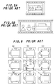
- Figs.6(a) to 6(i) indicate frame compositions which are viewed from the finder 701 of the camera of this example and can be taken thereby.
- a frame of thin line in the view-finder indicates an image pickup frame while points A, B, C and D are used for informing position-matching. That is, an indicator 710 indicates a horizontal movement while another indicator 711 indicates a vertical moment, respectively.
- the gyrosensor 704 automatically recognizes the direction of Fig.6(f) and causes the horizontal and vertical indicators 710 and 711 to exactly instruct the user to move the camera so that the point A in the view-finder in Fig.6(f) is positioned at the point D in the view-finder in Fig.6(e) while the point B in the view-finder in Fig.6(f) is positioned at the point C in the view-finder in Fig.6(e).
- the shutter is activated automatically or manually.
- the horizontal and vertical indicators 710 and 711 are made to instruct the user to move the camera so that the point B in the view-finder in Fig.6(c) is positioned at the point D in the view-finder in Fig.6(e).
- Fig.7 is a block diagram showing the display device.
- a microcomputer to be referred to hereinafter as a CPU 811 governs the whole control of the device.
- an analog/digital (A/D) converter 813 converts the analog image signal carrying a subject image taken by an image-pickup means 812, into digital image data.
- the output from the converter 813 is supplied to a frame memory 814 so that the output is stored therein.
- the frame memory 814 Connected to the CPU 811 are the frame memory 814; a photometering device 815 for metering the brightness of a subject; a display device 816 for displaying a moving quantity of the subject image, the photo-metered point etc.; an exposure controlling unit 817; a focusing device 818 for focusing the subject; a focus-activating switch 819 for activating the focusing device 818; a spotting switch 820 for setting up the spotted light metering mode and gaining the measurement in that mode; a clear switch 821 for setting up the averaged light measuring mode from the spotted light metering mode and gaining the measurement in that mode; and a sound generator 822 for generating sounds in response to the movement of the subject as well as when the switches 819 to 821 are operated.
- the image-pickup means 812 is composed of an imaging device such as, for example, CCDs, MOSs (Metal Oxide semiconductors) or the like.
- the CPU 811 is adapted to calculate the movement of the subject based on the digital image data stored in the frame memory 814.
- the CPU 811 is adapted to read out arbitrary image data in the frame memory 814 by designating a horizontal address (XADR) and a vertical address (YADR).
- This CPU 811 further effect exposure calculation and focusing calculation and the like.
- the exposure calculation is effected based on the metered value from the photometering device 815 whereas the focusing calculation is effected based on the image data to calculate focal length to a subject.
- a method of calculating the shift quantity of a subject by the CPU 811 will be described.
- a subject image FLa shown in Fig.8A is stored in the frame memory 814.
- the CPU 811 takes a summation (XSUM) of the values as to brightness signal for all the pixels along the vertical direction, for example.
- XSUM summation
- the CPU 811 takes another summation (YSUM) of the values as to brightness signal for all the pixels along the horizontal direction, for example, whereby one dimensional, Y-spectrum of summation signal YSa is obtained.
- YSUM summation of the values as to brightness signal for all the pixels along the horizontal direction
- the summation signal XSa as to that portion has higher values than the level of the other areas, as seen in Fig.8C.
- the thus detected horizontal (or X-directional) summation signal XSa and vertical (or Y-directional) summation signal YSa are temporarily stored in an unillustrated memory means such as a RAM (random access memory) or the like provided in the CPU 811.
- an unillustrated memory means such as a RAM (random access memory) or the like provided in the CPU 811.
- the CPU 811 similarly, detects X-directional and Y-directional summation signals XSb and YSb.
- the X-directional summation signal XSb and Y-directional summation signal YSb are in the forms of the spectrums shown in Figs.9B and 9C, respectively.
- the CPU 811 effects a calculation of a shift quantity in the horizontal direction, for example, as to the subject image frame. That is, The CPU 811 calculate the horizontal shift quantity of the subject image frame based on the correlative operation between the two X-directional summation signals XSa and XSb.
- the CPU 811 successively calculates absolute differential values between the two X-directional summation signals XSa and XSb by shifting the X-directional summation signal XSb as to the subject image FLb little by little relative to the X-directional summation signal XSa as to the subject image FLa, in order to seek a minimum absolute differential value. Based on this calculation, the CPU 811 determines the quantity where the minimum value is obtained, as to be the horizontal shift quantity of the subject image frame.
- Japanese Patent Application Hei 1 No.94,787 Japanese Patent Application Hei 1 No.94,787
- the video image is recorded when and only when the subject image in the frame changes. Therefore, this configuration is unfavorable to be applied to a portable type video camera because the subject image changes every time when the portable video camera is used. That is, the image is always recorded every time panning and tilting are effected using the portable video camera.
- the system searches variations of the current video image from the previous video image and effects recording or data transmitting of that portion. Therefore, it is impossible to detect that the image moves by an arbitrary amount of shift and effect recording. Further, in this prior art example, the variation of the image is detected based on the movement of the scanning stage. As in this conventional configuration, after the image data between before and after movement is correlated by electrically shifting the relative position of the current data to the previous data, a new image portion, if any, is detected from the magnitude of the correlated value. In such a case, despite that the image frame is not moved, the system could erroneously detect that the image frame is changed even when an image which has nothing to do with the previous image appears suddenly in the image frame.
- a gyro is used to detect the shift quantity.
- a gyro is an angular speed sensor, therefore, it is possible to determine the shift-angle by calculating a product of the angular speed and the time.
- the shift-angle equivalent to one-image frame differs depending on the zoomed position. That is, this conventional configuration is not constructed in view of such a system having a zoom lens, so that the application of the conventional configuration to the lens system with a zoom mechanism is unfavorable.
- the moved quantity of the image-pickup frame is determined by searching a shift quantity at which the absolute differential value between the current summation signal and the previous summation signal takes a minimum value as the summation signal of the brightness signal of the current video image is shifted relative to the summation signal of the brightness signal of the previous video image. Accordingly, if a view in which, for example, several trees having similar sizes are present by approximately like distances, is taken, there appear some places where the absolute differential value takes a minimum value as the current summation signal is shifted relative to the previous summation signal in either direction. Therefore, it could become hard, in some cases, to determine in which directions the camera is shifted.
- the indicator for informing the operator of the moved direction could indicate an opposite direction to the direction in which the camera is actually moved or the indicator suddenly could jump irregularly. To make matters worse, it was impossible for the operator to know whether the detected data is correct or not.
- a frame-shift detecting device in accordance with a first feature of the invention, comprises: an image-pickup portion outputting the video signal of picked up image frames; a movement-vector detecting portion determining a movement-vector between image frames by comparing a preceding image frame with a current image frame by a field or by a frame as a unit, the image frames being formed from the video signal from the image-pickup portion; and a frame-shift detecting portion for summing up horizontal and vertical components of the movement-vector, separately in order to detect a shift-direction or shift-quantity of the image-pickup frame from the start of counting operation.
- a frame-shift detecting device in accordance with a second feature of the invention, comprises: an image-pickup portion outputting the video signal of picked up image frames; a movement-vector detecting portion determining a movement-vector between image frames by comparing a preceding image frame with a current image frame by a field or by a frame as a unit, the image frames being formed from the video signal from the image-pickup portion; and a view-field shift angle calculating portion for determining a horizontal or vertical view-field shift angle, and is constructed such that the horizontal or vertical view-field shift angle is determined by the steps of: summing up horizontal or vertical components of the movement-vector, separately to determine a horizontal or vertical shift-quantity of the image-pickup frame; and calculating the shift angle in question, based on the shift-quantity, a predetermined shift quantity for one-frame and a predetermined view-field angle for one-frame.
- a video recording apparatus in accordance with a third feature of the invention comprises: an image-pickup portion outputting the video signal of picked up image frames; a video recording portion for recording the video signal by a field or a frame as a unit; a movement-vector detecting portion determining a movement-vector between image frames by comparing a preceding image frame with a current image frame by a field or by a frame as a unit, the image frames being formed from the video signal from the image-pickup portion; and a frame-shift detecting portion for summing up horizontal and vertical components of the movement-vector, separately in order to detect a shift-direction or shift-quantity of the image-pickup frame from the start of counting operation, and is constructed such that the video recording portion records first video information as to a first frame at the start of counting operation and second video information as to a second frame at the time when the frame-shift detecting portion detects that the image pickup frame has been shifted by a predetermined shift quantity.
- a video recording apparatus in accordance with fourth feature of the invention, comprises: an image-pickup portion outputting video signal of picked up image frames; a video recording portion for recording the video signal by a field or a frame as a unit; a movement-vector detecting portion determining a movement-vector between image frames by comparing a preceding image frame with a current image frame by a field or by a frame as a unit, the image frames being formed from the video signal from the image-pickup portion; and a frame-shift detecting portion for summing up horizontal and vertical components of the movement-vector, separately in order to detect a shift-direction or shift-quantity of the image-pickup frame from the start of counting operation, and is constructed such that the video recording portion, as recording the video signal continuously, records a first pilot signal at the start of counting operation and a second pilot signal at the time when the frame-shift detecting portion detects that the image pickup frame has been shifted by a predetermined shift quantity.
- a video recording apparatus in accordance with a fifth feature of the invention comprises: an image-pickup portion outputting the video signal of picked up image frames; a video recording portion for recording the video signal by a field or a frame as a unit; a monitor portion displaying the image frame to be recorded on the video recording portion; a movement-vector detecting portion determining a movement-vector between image frames by comparing a preceding image frame with a current image frame by a field or by a frame as a unit, the image frames being formed from the video signal from the image-pickup portion; and a frame-shift detecting portion for summing up horizontal and vertical components of the movement-vector, separately in order to calculate a shift direction, a shift-quantity and a reference shift speed of the image frame as well as to detect a shift-direction or shift-quantity of the image-pickup frame from the start of counting operation, wherein the monitor portion is constructed so that based on the data from the frame-shift detecting portion, the shift quantity of the image-pickup
- a video recording apparatus in accordance with a sixth feature of the invention comprises: an image-pickup portion outputting the video signal of picked up image frames; a movement-vector detecting portion determining a movement-vector between image frames by comparing a preceding image frame with a current image frame by a field or by a frame as a unit, the image frames being formed from the video signal from the image-pickup portion; a shift-angle specifying portion for designating a shift angle of the image-pickup portion; a view-field shift angle detecting portion wherein a horizontal or vertical shift-quantity of the image-pickup frame is determined by summing up horizontal or vertical components of the movement-vector, a horizontal or vertical view-field shift angle is determined based on the determined shift-quantity, a predetermined shift quantity for one-frame and a predetermined view-field angle for one-frame, and the determined view-field shift angle is compared with the specified shift-angle set up through the shift-angle specifying portion to detect whether the two values coincide to each other; and
- a video recording apparatus in accordance with seventh through ninth features of the invention is constructed such that the frame-shift detecting portion having any one of the third through fifth features of the invention comprises a determining portion for determining whether the image-pickup frame is moved in the horizontal direction or in the vertical direction, and based on the determination, the movement of the image-pickup frame is detected as to any one of the horizontal and vertical directions.
- a video recording apparatus in accordance with tenth through twelfth features of the invention is constructed such that the determining portion having any one of the seventh through ninth features of the invention determines an operation to be erroneous when, after the moving direction of the image-pickup frame is detected, the image-pickup frame is detected to be shifted in a direction inconsistent with the detected direction.
- the video recording apparatus of the present invention is featured as described heretofore; thus the following favorable results are expected.
- the shift quantity of the image-pickup frame from the start of counting operation and the shift direction thereof can be determined with precision by detecting the movement of the image-pickup frame based on the video signal of the subject during image-taking to extract movement-vector data, and analyzing the movement-vector data thus obtained.
- the frame-shift detecting device of the second feature it is possible to determine a field-view shift angle during panning (horizontal rotation) or tilting (vertical rotation), by detecting the movement of the image-pickup frame based on the video signal of the subject during image-taking to extract movement-vector data, and analyzing the movement-vector data thus obtained.
- the video recording apparatus of the third feature when the camera is panned or tilted, it is possible to record an image frame at the start of moving and another image frame which is obtained after the movement and spaced from the first frame by an arbitrary integer number of frame-lengths and it is possible to arrange the two image frames to be a spatially combined frame.
- this apparatus is connected to a video printer and the arbitrary integer number is set at 1, two spatially continuously recorded image frame can be printed out to create a panoramic photograph.
- the video recording portion as recording the video signal of time-continuous image frames, records a first pilot signal with a first image frame at the start of counting operation, and a second pilot signal with a second image frame which is obtained after an arbitrary shift quantity has been moved.
- the recorded signal is reproduced, the two image frames before and after the movement can be recognized by detecting respective pilot signals.
- this apparatus is connected to a video printer and the arbitrary shift quantity is set at one-frame length, two spatially continuously recorded image frame similar to the above invention can be printed out to create a panoramic photograph.
- an actual shift quantity of the image-pickup frame from the start of counting operation and a reference shift speed of the image-pickup frame are displayed on the monitor portion, whereby it is possible for the operator to move the camera with precision by matching the shift speed in conformity with the reference indicator when the camera is to be panned or tilted.
- the operator is able to specify the moving range of the view-field shift angle for panning or tilting.
- this setup it is possible to automatically pan or tilt the camera within the range of the view-field shift angle.
- any of the third to fifth configurations it is possible to automatically determine whether an operation is effected in the panning or tilting mode, by detecting the shift direction of the frame. Accordingly, based on the result of the determination, it is possible to perform a pertinent process to panning or tilting.
- any of the seventh to ninth configurations after the determination of whether an operation is effected in the panning or tilting mode, if any shift of the frame in a direction inconsistent with an expected direction based on the determination is detected, the movement is determined to be erroneous, whereby it is possible to quit the operation.
- Fig.10 is a block diagram showing an embodiment of a frame-shift detecting device in accordance with the first feature of the invention.
- light having passed through a lens 1 is photoelectrically converted into electric signals by means of a CCD imaging device 2 and the thus converted electric signal is transmitted to a signal processing portion 3.
- the inputted electric signal is separated into the luminance signal containing brightness information and the chromatic signal containing color information while several synchronizing signals are added to the inputted signal and the thus treated signal is outputted to a next step (not shown).
- the signal processing portion 3 digitally supplies luminance signals required for detecting the movement of image to a movement-vector detecting portion 4.
- the lens 1, the CCD imaging device 2 and the signal processing circuit 3 constitute an image-pickup unit.
- the movement-vector detecting portion 4 detects a movement vector by the 'representative point matching method'. This method is carried out as follows: That is, one frame is divided into a plurality of blocks. An absolute differential value between the luminance values of the previous frame and the current frame is determined for every representative point selected one in each block. All the values for representative points are summed up over the whole frame. Based on the summation thus obtained and the previously obtained summation, two-dimensional shift quantity and the summation are analyzed to detect a movement vector.
- Fig.11 is a block diagram showing the movement-vector detecting portion 4, which is composed of a preprocessing portion 41, a correlation calculating portion 42, a memory portion 43 and a detecting portion 44.
- the preprocessing portion 41 compensates the luminance signal from the signal processing portion 3 by interpolating one-line shift in the vertical direction between even-numbered fields and odd-numbered fields due to the interlaced scanning scheme, and reduces the high-frequency noises through a digital filter.
- the detecting portion 44 evaluates the correlation between the luminance signals of the previous field image and the current field image based on the result of the correlation calculating portion 42.
- the movement vector (Vi, Vj) thus detected by the matching method will take only integer values because the unit of the shift amount between the two images is one pixel. To make matters worse, each image has been thinned or interlaced by every two lines. That is, the detecting resolution is two-pixel length, resulting in poor accuracy.
- the quadratic-curve interpolation is used. That is, using the summation values around the minimum value of the summation correlation, the quadratic-curve interpolation is effected, so that the movement vector having a resolution of not more than one-pixel can be obtained.
- hx is two-pixel length while hy is two-pixel length (frame).
- the thus determined movement vector is outputted as the shift quantity in the horizontal and vertical directions to the frame-shift detecting portion 5.
- the movement-vector detecting portion 4 outputs a signal that instructs the end of the detection.
- the frame-shift detecting portion 5, as receiving this signal, is activated to operate.
- Fig.13 is a block diagram showing an embodiment of the frame-shift detecting portion 5. That is, the frame-shift detecting portion 5 includes: latch circuits 51a and 51b which separately latch the horizontal and vertical components of the movement-vector data outputted by every field from the movement-vector detecting portion 4; summing circuits 52a and 52b for separately adding the horizontal and vertical components of the latched movement-vector data to respective horizontal and vertical summations, from the start of counting operation; a shift-direction determining circuit 53 for determining a shift direction of the frame based on the summations; and a shift-angle calculating circuit 54 for calculating a shift-angle of the frame based on the same summations.
- latch circuits 51a and 51b which separately latch the horizontal and vertical components of the movement-vector data outputted by every field from the movement-vector detecting portion 4
- summing circuits 52a and 52b for separately adding the horizontal and vertical components of the latched movement-vector data to respective horizontal and vertical summations,
- the latch circuit 51a and 51b separately latch the horizontal and vertical components of the movement-vector data outputted by every field from the movement-vector detecting portion 4 (Steps S10 and S11).
- the horizontal component of the latched movement-vector data is added in the summing circuit 52a to the summation of the horizontal components of the movement-vector data from the start of counting operation (Step S12) while the vertical component of the latched movement-vector data is added in the summing circuit 52b to the summation of the vertical components of the movement-vector data from the start of counting operation (Step S13).
- the summations indicate shift-quantitieS in the horizontal and vertical directions, from the start of counting operation.
- the shift-direction of the frame is determined by the shift-direction determining circuit 53, from the summations (totaled values) of the horizontal and vertical components of the movement-vector data (Step S14).
- the state is determined as non-movement.
- the summation of the horizontal component is positive (+)
- the state is determined as a right-ward movement.
- the summation of the vertical component is positive (+)
- the state is determined as an upward movement.
- the state is determined as a right-upward movement; and when the summations of the horizontal and vertical components are both negative (-), the state is determined as a left-downward movement.
- the shift-quantities of the frame in the horizontal and vertical directions are determined, respectively.
- the moved angle of the frame is calculated (Step S15). For example, suppose that the summation of the horizontal components is 100 when one-frame length is shifted. If the detected summation value is 50, it is recognized that the frame is moved by one half-frame length and if the summation value is 200, it is recognized that the frame is moved by two-frame length. Similarly, the shift in the vertical direction is determined.
- the shift-angle detecting circuit 54 calculates the shift-angle of the frame from the thus determined horizontal and vertical shift-quantities.
- the shift-quantity and shift-direction of the frame it is possible to detect exact quantities of the shift of the frame, that is, the shift-quantity and shift-direction of the frame.
- the operator as checking the information, becomes able to move the camera by an arbitrary amount, such as one-third of the whole frame angle or by two-fifth of the whole frame angle, thus obtaining increased degrees of freedom during the image-pickup operation.
- Fig.15 is a block diagram showing an embodiment of a frame-shift detecting device in accordance with the second feature of the invention.
- an image-pickup unit composed of a lens 1, a CCD imaging device 2 and a signal processing circuit 3, and a movement-vector detecting portion 4 have the same configurations and operations with those of the previous embodiment. Therefore, detailed description is omitted.
- This embodiment has a view-field shift angle detecting portion 6 disposed in the downstream of the movement-vector detecting portion 4.
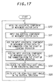
- This view-field shift angle detecting portion 6 includes, as shown in Fig.16, latch circuits 61a and 61b which separately latch the horizontal and vertical components of the movement-vector data outputted by every field from the movement-vector detecting portion 4; summing circuits 62a and 62b for separately adding the horizontal and vertical components of the latched movement-vector data to respective horizontal and vertical summations, from the start of counting operation; and view-field shift angle calculating circuits 63a and 63b for determining horizontal and vertical components of the view-field shift angle.
- the latch circuit 61a and 61b separately latch the horizontal and vertical components of the movement-vector data outputted by every field from the movement-vector detecting portion 4 (Steps S20 and S21).
- the horizontal component of the latched movement-vector data is added in the summing circuit 62a to the summation of the horizontal components of the movement-vector data from the start of counting operation (Step S22) while the vertical component of the latched movement-vector data is added in the summing circuit 62b to the summation of the vertical components of the movement-vector data from the start of counting operation (Step S23).
- the summations indicate shift-quantities in the horizontal and vertical directions, from the start of counting operation.
- the view-field shift angle calculating circuit 63a calculates the horizontal view-field shift angle, from the summations of the horizontal component of the movement-vector data (Step S24) while the view-field shift angle calculating circuit 63b calculates the vertical view-field shift angle, from the summations of the vertical component of the movement-vector data (Step S25).
- the horizontal view-field angle and vertical view-field angle for one-frame take respective predetermined values, depending upon the optical system of the lens used. For example, suppose that the horizontal view-field angle for one-frame is expressed as ⁇ x°, the vertical view-field angle for one-frame is ⁇ y°, the summation (shift quantity) of the horizontal component of the movement vector outputted from the movement-vector detecting portion 4 is Mx, the summation of the vertical components of the movement vector is My, the shift quantity when the view field is shifted by one-frame length in the horizontal direction is Px, and the shift quantity when the view field is shifted by one-frame length in the vertical direction is Py.
- Figs.18A, 18B and 18C are illustrative views for explaining the operation of this embodiment.
- the horizontal view-field angle before movement is represented by an angle ⁇ 1 while the horizontal view-field angle after movement is represented by an angle ⁇ 2.
- the frame of the angle ⁇ 1 picks up the subject SB from the front as shown in Fig.18B while the frame of the angle ⁇ 2 picks up the right-half of the subject SB as shown in Fig.18B.
- the view-field angles ⁇ 1, ⁇ 2 are constant.
- horizontal view-field angle ⁇ x° for one-frame 45°.
- the vertical view-field shift angle can be calculated in the same manner.
- the operator can get information on the swing angle of the camera when the camera is panned or tilted during picture-taking. This feature is useful when a predetermined amount of panning or tilting is to be done.
- Fig.19 is a block diagram showing an embodiment of a video recording apparatus in accordance with the third, the seventh through ninth and the tenth through twelfth features of the invention.
- an image-pickup unit composed of a lens 1, a CCD imaging device 2 and a signal processing circuit 3, and a movement-vector detecting portion 4 have the same configurations and operations with those of the previous embodiment. Therefore, detailed description is omitted.
- a VTR (Video Tape Recorder) 7 is connected to the output side of the signal processing portion 3.
- a monitor portion 8 for displaying video image to be recorded on the VTR 7 or to be reproduced from the VTR 7 is connected to the VTR 7.
- Connected to the output side of the movement-vector detecting portion 4 is a frame-shift detecting portion 9. All the above components, or the lens 1 through the frame-shift detecting portion 9 constitute a camera-integrated VTR with a built-in monitor.
- Fig.20 is a block diagram showing an embodiment of the frame-shift detecting portion 9.
- This frame-shift detecting portion 9 includes: latch circuits 91a and 91b which separately latch the horizontal and vertical components of the movement-vector data outputted by every field from the movement-vector detecting portion 4; summing circuits 92a and 92b for separately adding the horizontal and vertical components of the latched movement-vector data to respective horizontal and vertical summations, from the start of counting operation; a pan/tilt determining circuit 93 for determining whether panning and/or tilting is effected, by checking the horizontal summation and the vertical summation; a selecting circuit 94 for selecting one of the summations outputted from the summing circuits 92a and 92b, based on the result of the determination in the pan/tilt determining circuit 93; a reference value generating circuit 95 for outputting a shift-quantity for each one-frame as a reference value, based on the result of the determination in the pan/
- Step S30 the memory portion 43 in the movement-vector detecting portion 4 may commonly be used for the image memory.
- the latch circuit 91a and 91b separately latch the horizontal and vertical components of the movement-vector data outputted by every field from the movement-vector detecting portion 4 (Steps S31 and S32). Subsequently, the horizontal component of the latched movement-vector data is added in the summing circuit 92a to the summation of the horizontal components of the movement-vector data from the start of counting operation (Step S33) while the vertical component of the latched movement-vector data is added in the summing circuit 92b to the summation of the vertical components of the movement-vector data from the start of counting operation (Step S34).
- the summations indicate shift-quantities in the horizontal and vertical directions, from the start of counting operation.
- Step S35 whether determination of pan/tilt is made is determined by the pan/tilt determining circuit 93 (Step S35).
- the step is done because this embodiment is to record a panorama video picture spatially continuously in the horizontal direction or in the vertical direction by panning or tilting the camera and the following operation becomes different depending on panning or tilting.
- Step S36 Since, at the start of the mode, or when the camera stands still, the determination of pan/tilt has not been done, the determination of pan/tilt is effected (Step S36).
- the absolute value of the output from the summing circuit 92a is detected to be more than a certain level and the absolute value of the output from the summing circuit 92b is detected to be not more than a certain level, the movement is determined as a panning operation, and the system sets up the panning mode (Step S37).
- the camera is determined to have been moved two-dimensionally. Accordingly, in some cases depending upon the amount of the shift, the spatially continuous panoramic video taking becomes impossible, so that the system determines the operation as an error.
- the first video image stored in the image memory is made clear and all the circuits related are reset and the error message is displayed on the monitor portion 8, to thereby end the operation (Step S39).
- Step S31 When the absolute values of the output from both the summing circuits 92a and 92b are both zero or not more than certain levels, the camera is determined not to have been moved yet, so that Step S31 and the following steps are repeated. In this case, if the camera has not been moved after the lapse of a predetermined time from the start of the operation, the operation is determined to be erroneous, and the process in Step S39 is effected to end the operation.
- a setup operation of the panning mode (Step S37) is to cause the selecting circuit 94 to select the output from the summing circuit 92a and to cause the reference value generating circuit 95 to generate a reference value equivalent to the shift quantity of one frame length in the horizontal direction.
- a setup operation of the tilting mode (Step S38) is to cause the selecting circuit 94 to select the output from the summing circuit 92b and to cause the reference value generating circuit 95 to generate a reference value equivalent to the shift quantity of one frame length in the vertical direction.
- Step S40 a judgment of whether any erroneous operation occurs is made in the pan/tilt determining circuit 93 (Step S40).
- This process is provided to deal with such cases that, for example, after the operation is determined as in the panning mode and the panning mode is set up, the camera is moved significantly in the vertical direction, or after the operation is determined as in the tilting mode and the tilting mode is set up, the camera is moved significantly in the horizontal direction. In any of such cases, it becomes impossible to record a panoramic video image spatially continuous. Accordingly, the error treatment is a must.
- the first video image stored in the image memory is made clear and all the circuits related are reset and the error message is displayed on the monitor portion 8, to thereby end the operation (Step S39).
- Step S37 When the setup of the panning mode (Step S37) or the tilting mode (Step S38) is complete, and if the operation is determined to be free from error in the Step S40, a judgment of whether the movement from the start of the operation is more than one-frame length is made in the comparing circuit 96 (Step S41). If the movement has not exceeded yet, the same process is repeated from Step S31 wherein the horizontal and vertical components of the movement-vector data outputted by every field from the movement-vector detection portion 4 are separately latched and summed up. Since the movement has not exceeded the one-frame length at the outset of the operation, the process from Step S31 and the following steps is effected.
- Step S41 if the summation of the movement-vector data becomes equal to or greater than one-frame length, one field of the video image at that time should be stored into the image memory in the signal processing portion 3, as a second frame (an image after one-frame length is moved) (Step S42).
- the VTR 7 is controlled so that the spatially continuous two frames of video signals stored in the signal processing portion 3 are recorded onto the magnetic tape for some seconds for each (Step S43). Subsequently, the two frames of the video signals stored in the signal processing portion 3 are made clear, and all the circuits related are reset (Step S44) to end the operation.
- the system can be configurated so that the video signal for the first frame may be recorded onto the VTR 7 immediately after the signal for the first frame is stored into the image memory, thereafter the video signal for the second frame may be recorded onto the VTR 7 immediately after the signal for the second frame is stored into the image memory. This method allows saving of the image memory.
- Figs.22A through 22D are views showing an example of recorded images in accordance with this embodiment.
- the VTR 7 records an image frame SB1 shown in Fig.22B for some seconds as a frame at the start of counting operation, and then effects recording of an image frame SB2 shown in Fig.22C for some seconds as a second frame after the one-frame length has been panned.
- the operator In reproducing the thus recorded two video images SB1 and SB2 from the VTR 7, the operator, as observing the playback picture displayed on the monitor portion 8, may make a printout operation by means of a video printer 10 which is connected to the output terminal of the VTR 7. By this operation, a panoramic photograph spatially continuous can be created as shown in Fig.22D.
- Fig.23 is a block diagram showing an example of a video recording apparatus in accordance with the fourth, the seventh through ninth and the tenth through twelfth features of the invention.
- an image-pickup unit composed of a lens 1, a CCD imaging device 2 and a signal processing circuit 3, and a movement-vector detecting portion 4 have the same configurations and operations with those of the previous embodiment. Therefore, detailed description is omitted.
- a VTR 7 as a video recording apparatus is connected to the output side of the signal processing portion 3.
- a monitor portion 8 for displaying video image to be recorded on the VTR 7 or to be reproduced from the VTR 7 is connected to the VTR 7.
- Connected to the output side of the movement-vector detecting portion 4 is a frame-shift detecting portion 9. All the above components, or the lens 1 through the frame-shift detecting portion 9 constitute a camera-integrated VTR with a built-in monitor.
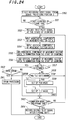
- Step S50 the video signal which is time-continuously outputted from the signal processing portion 3 is recorded continuously on the magnetic tape of the VTR 7 (Step S50).
- a control signal having a waveform periodically changing in a ratio of 60 ⁇ 5% to 40 ⁇ 5% as shown in Fig.25A is simultaneously recorded by every field on the control track of the magnetic tape.
- the frame-shift detecting portion 9 resets internal circuits and starts counting of one-frame shift (Step S51) while a pilot signal indicating the start of counting operation is recorded on the tape (Step S52).
- the above control signal is made to also serve as the pilot signal, by changing the duty ratio of the control signal into the ratio of 70 ⁇ 5% to 30 ⁇ 5% as shown in Fig.25B.
- the pilot signal should not be limited to this configuration, as will be shown hereinafter.
- Step S53 to Step S63 is effected. Since a series of these steps are the same with those from Step S31 to Step S41 shown in Fig.21 in the previous embodiment, the detailed description is omitted. However, since in this embodiment the video signal is continuously recorded on the VTR 7; when the operation is determined as to be an error in Step S58 or Step S63, only the error message is displayed (Step S61), and the operation is ended.
- Step S63 when the summation of the movement-vector data is determined to be equal to or more than one-frame length, a pilot signal indicating that one-frame has been shifted is recorded on the magnetic tape by the VTR 7, (Step S64) and the operation is ended.
- the control signal is made to also serve as this pilot signal, by changing the duty ratio of the control signal into the ratio of 80 ⁇ 5% to 20 ⁇ 5% as shown in Fig.25C.
- Figs.26A through 26C are views showing an example of video recording in accordance with this embodiment, when a subject SB shown in Fig.26A is taken as the camera is panned continuously from the left to the right.
- Fig.26B shows a series of the image taking situations as the camera is being panned.
- the frame recorded at the start of counting operation is a frame SBc marked with a white star.
- the control signal of the ratio shown in Fig.25B which also serves as the pilot signal is recorded on the control track.
- the frame recorded after one-frame length has been shifted is a frame SBh marked with a black star.
- the control signal of the ratio shown in Fig.25C which also serves as the pilot signal is recorded on the control track.
- the image frame SBc added with the first pilot signal and the image frame SBh added with the second pilot signal are reproduced as a single spatially continuous frame as shown in Fig.26C.
- the information of the two image frames added with the pilot signals is sent to a video printer 10 for printout, whereby it is possible to create a spatially continuous panoramic photograph.
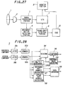
- Fig.27 is a block diagram showing an example of a video recording apparatus in accordance with the fifth, the seventh through ninth and the tenth through twelfth features of the invention.
- an image-pickup unit composed of a lens 1, a CCD imaging device 2 and a signal processing circuit 3, and a movement-vector detecting portion 4 have the same configurations and operations with those of the previous embodiment. Therefore, detailed description is omitted.
- a VTR 7 is connected to the output side of the signal processing portion 3.
- a monitor portion 8 for displaying video image to be recorded on the VTR 7 or to be reproduced from the VTR 7 is connected to the VTR 7.
- Connected to the output side of the movement-vector detecting portion 4 is a frame-shift detecting portion 11.
- Connected to the output side of the frame-shift detecting portion 11 is an on-screen display (OSD) circuit 12.
- the OSD circuit 12 is a circuit for generating designated titles such as characters, marks etc., superimposed on the screen of the monitor portion 8. All the above components, or the lens 1 through the OSD circuit 12 constitute a camera-integrated VTR with a built-in monitor.
- Fig.28 is a block diagram showing an embodiment of a frame-shift detecting portion 11.
- the same components in this portion 11 with those in the frame-shift detecting potion 9 as already described are allotted with the same reference numerals and the detailed description is omitted.
- the frame-shift detecting portion 11 includes; latch circuits 91a, 91b, summing circuits 92a, 92b, a pan/tilt determining circuit 93, a selecting circuit 94, a reference value generating circuit 95, and a comparing circuit 96.
- the portion 11 further has a reference shift-quantity calculating circuit 97 and an actual shift-quantity calculating circuit 98, both connected in parallel with the pan/tilt determining circuit 93.
- the reference shift-quantity calculating circuit 97 is a circuit for calculating a reference speed in order to make the operator move the frame at a speed which allows the system to detect the movement-vector data with good accuracy.
- the calculated reference speed data is displayed on the monitor portion 8.
- the actual shift-quantity calculating circuit 98 is a circuit for calculating an actual shift speed in order to inform the operator of the actual moving speed of the camera.
- the calculated actual speed data is displayed on the monitor portion 8.
- the output from the reference shift-quantity calculating circuit 97 as well as the output from the actual shift-quantity calculating circuit 98 is delivered to a data converting circuit 99, where the data is converted into display data instructing the display of characters, marks etc., to be outputted to the OSD 12.
- Step S70 to Step S82 is the same with that from Step S50 to Step S62 shown in Fig.24 in the previous embodiment, the detailed description is omitted.
- Step S83 the reference shift-quantity calculating circuit 97 calculates a reference shift-quantity (Step S83). This calculation is done in order to make the operator move the frame of the camera at a speed which allows the system to detect the movement-vector data with good accuracy and this calculated reference speed is displayed on the monitor portion 8.
- the value of the movement-vector data transmitted by every field from the movement-vector detecting portion 4 is 10.
- the increasing rate of the summation of the movement-vector data can be assumed to be a reference speed when the movement-vector data is detected with good accuracy.
- the value of the movement-vector data transmitted by every field from the movement-vector detecting portion 4 is 10.
- the actual shift-quantity calculating circuit 98 calculates an actual shift quantity of the image-pickup frame by the movement of the camera from the start of counting operation (Step S84).
- the previously determined reference data and the data indicating the actual shift quantity are converted in the data converting circuit 99 into display data (Step S85).
- the converted data is outputted to the OSD 12 (Step S86).
- the OSD 12 outputs character signals etc., in conformity with the converted data, to the monitor portion 8.
- the monitor portion 8 displays a video image based on the video signal outputted from the signal processing portion 3 with the characters and the like superimposed based on the character signals etc., outputted from the OSD 12.
- Step S87 a judgment of whether the movement is more than one-frame length is made in the comparing circuit 96 (Step S87). If the movement has not exceeded yet, the same process is repeated from Step S73 wherein the horizontal and vertical components of the movement-vector data outputted by every field from the movement-vector detection portion 4 are separately latched and summed up.
- a pilot signal indicating that one-frame has been shifted is recorded on the magnetic tape of the VTR 7 (Step S88) in response to the output from the comparing circuit 96. Then, the operation is ended.
- the control signal is made to also serve as the pilot signal, by changing the duty ratio of the control signal into the ratio of 80 ⁇ 5% to 20 ⁇ 5% as shown in Fig.25C.
- Fig.30A is a display immediately after the start of the panning.
- An upper bar Br1 is an indicator showing the reference-shift speed while a diamond-shaped mark Br2 is an indicator showing the actual-shift speed.
- Lines Sh are the horizontal references, whereas lines Sv are the vertical references.
- Fig.30B shows a case where the camera is shifted downward immediately after the start of movement, therefore the diamond mark Br2 is positioned below as compared to the position in Fig.30A.
- Fig.30C is a display showing a situation in the course of panning.
- the bar Br1 indicating the reference-shift speed is in advance as compared to the diamond Br2 indicating an actual-shift speed. This indicates that the actual-shift speed is delayed relative to the reference-shift speed.
- the operator as checking the display, should move the camera so that the diamond Br2 may move together with the reference indicator, whereby it is possible to effect panning of the camera with precision.
- another bar Br3 is displayed for the comparison with the bar Br1.
- Fig.30D is a display showing a situation immediately after the shift end. The operator should stop panning of the camera when the diamond Br2 reaches this position.
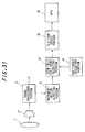
- Fig.31 is a block diagram showing an example of a video recording apparatus in accordance with the sixth feature of the invention.
- an image-pickup unit composed of a lens 1, a CCD imaging device 2 and a signal processing circuit 3, and a movement-vector detecting portion 4 have the same configurations and operations with those of the previous embodiment. Therefore, detailed description is omitted.
- This embodiment has a view-field shift angle detecting portion 13 connected to the output side of the movement-vector detecting portion 4.
- This view-field shift angle detecting portion 13 is to control a pan/tilt driver portion 15 within a view-field angle designated by a shift-angle specifying portion 14.
- This pan/tilt driver portion 15 drives the automatic panning head (APH) 16 attached to the camera.
- APH automatic panning head
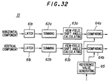
- Fig.32 is a block diagram of an embodiment of the view-field shift angle detecting portion 13.
- the view-field shift angle detecting portion 13 includes latch circuits 61a and 61b; summing circuits 62a and 62b; and view-field shift angle calculating circuits 63a and 63b and further has comparing circuits 64a and 64b connected to the output side of the view-field shift angle calculating circuits 63a and 63b, respectively.
- the comparing circuit 64a and 64b is made to receive reference data in accordance with an indicating angle which is generated from a reference value generating circuit 65 based on the instruction from the shift-angle specifying portion 14.
- Step S90, S91 the operator inputs specified shift-angles as to the horizontal and vertical directions through the shift-angle specifying portion 14 (Steps S90, S91).
- the specified shift-angle in the vertical direction is zero
- the specified shift angle in the horizontal direction is zero.
- Step S92 movement-vector data is outputted by every field from the movement-vector detecting portion 4.
- the latch circuits 61a and 61b separately latch the horizontal and vertical components of the movement-vector data (Steps S93 and S94).
- Step S95 the horizontal component of the latched movement-vector data is added to the summation of the horizontal components of the movement-vector data from the start of counting operation
- Step S96 the vertical component of the latched movement-vector data is added to the summation of the vertical components of the movement-vector data from the start of counting operation
- Step S97 and S98 calculations for determining the view-field shift angle are performed.
- the processes from Steps S93 to S98 are the same with those from Steps S20 to S25 already shown in Fig.17, so that a further description in detail is omitted.
- the horizontal view-field shift angle determined by the view-field shift angle calculating circuits 63a is compared with the data in accordance with the specified horizontal angle outputted from the reference value generating circuit 65 (Step S99).
- the pan/tilt driver portion 15 is controlled to drive the APH 16 so that the panning direction of the camera can be reversed (Step S100).
- the comparing circuit 64b the vertical view-field shift angle determined by the view-field shift angle calculating circuits 63b is compared with the data in accordance with the specified vertical angle outputted from the reference value generating circuit 65 (Step S101). As a result of the comparison, if the vertical view-field shift angle is greater than the specified angle, the pan/tilt driver portion 15 is controlled to drive the APH 16 so that the tilting direction of the camera can be reversed (Step S102).
- Step S102 When the vertical view-field shift angle is equal to or smaller than the specified angle, or when the process at Step S102 is complete, the operation is returned to the process in Step S93, from where the same process is repeated, that is, the separate input of the horizontal and vertical components of the movement-vector data outputted by every field from the movement-vector detecting portion 4 is repeated.
- the rotational direction of the camera is reversed at Step 100 or Step 102, it is also possible that the rotation of the camera is merely stopped.
- the present invention is not limited to this configuration. That is, other video recording apparatuses may of course be applied to the invention, such as, for example, semiconductor memory devices including a flash memory, a nonvolatile ferroelectric memory etc., magnetic recording and reproducing apparatuses using an FD (floppy disc) or the like, or magneto-optical recording and reproducing apparatuses using a CD-ROM or the like. Accordingly, the present invention should not be limited to the VTR having a built-in camera.
- the present invention is not limited to this configuration.
- the system may be constructed such that the operator may manually select a mode from the panning or tilting mode or the system may be dedicated to the panning mode or the tilting mode.
- the present invention is not limited to this configuration.
- the shift amount to be detected may of course be set at any arbitrary quantity.
- the present invention is not limited to this configuration.
- the pilot signal can be recorded as a proper signal, into the PCM areas of 8 mm VTR, the sub-code areas of the digital VTR or etc.
- the pilot signal pertinent to the specifications of the apparatus may and should be recorded.
- the shift quantity of the image-pickup frame from the start of counting operation can be determined with precision, based on the video signal of the frames during image-taking. Further, the view-field shift angle during panning or tilting can also be determined with precision.
- a first image frame at the start of moving and a second image frame at the end of moving are recorded sequentially, or the two images are recorded together with respective pilot signals so that the recorded frames in question may be specified.
- Any of the above configurations makes it possible to record two spatially continuous image frames and reproduce the two frames as a single picture. As a result, it becomes possible to print out the two continuous frames by means of a video printer. Alternatively, it is also possible to display the two images in two monitor arranged side by side to create a wide panoramic image frame.
- the video recording apparatus of the fifth feature of the invention it is possible to display an exact shift quantity of the image-pickup frame by detecting the movement of the whole frame with precision. Further, an actual shift quantity of the image-pickup frame is displayed together with a reference speed at which the frame would be moved accurately. This function allows the operator to move the frame with precision. Since the apparatus can be downsized and made light-weighted, it can be easily handled for being carried and moved as well as for picture taking.
- a moving range of the view-field shift angle can be specified by the operator and automatic panning or tilting of the camera can be effected within the specified range. Accordingly, although in the prior art configuration, the operation of panning or tilting could be done at only predetermined angles, it is possible to change the moving range of the view-field shift angle, in conformity with the scene to be taken. Accordingly, the degrees of freedom in the image taking can be improved.
- the movement is determined to be erroneous, whereby it is possible to quit the operation.
Landscapes
- Engineering & Computer Science (AREA)
- Multimedia (AREA)
- Signal Processing (AREA)
- Studio Devices (AREA)
- Television Signal Processing For Recording (AREA)
- Compression Or Coding Systems Of Tv Signals (AREA)
- Image Processing (AREA)
- Studio Circuits (AREA)
- Image Analysis (AREA)
Applications Claiming Priority (2)
| Application Number | Priority Date | Filing Date | Title |
|---|---|---|---|
| JP6136495A JP3253478B2 (ja) | 1995-03-20 | 1995-03-20 | 映像記録装置 |
| JP61364/95 | 1995-03-20 |
Publications (2)
| Publication Number | Publication Date |
|---|---|
| EP0734155A1 true EP0734155A1 (fr) | 1996-09-25 |
| EP0734155B1 EP0734155B1 (fr) | 2006-03-08 |
Family
ID=13169045
Family Applications (1)
| Application Number | Title | Priority Date | Filing Date |
|---|---|---|---|
| EP19950308792 Expired - Lifetime EP0734155B1 (fr) | 1995-03-20 | 1995-12-05 | Dispositif de détection de déplacement de trame, appareil de prises de vues et d'enregistrement vidéo avec mode panoramique |
Country Status (8)
| Country | Link |
|---|---|
| EP (1) | EP0734155B1 (fr) |
| JP (1) | JP3253478B2 (fr) |
| KR (1) | KR100211484B1 (fr) |
| AU (1) | AU689999B2 (fr) |
| CA (1) | CA2164238C (fr) |
| DE (1) | DE69534836T2 (fr) |
| ES (1) | ES2258263T3 (fr) |
| MY (1) | MY115454A (fr) |
Cited By (12)
| Publication number | Priority date | Publication date | Assignee | Title |
|---|---|---|---|---|
| EP0884897A1 (fr) * | 1997-06-11 | 1998-12-16 | Hitachi, Ltd. | Caméra panoramique numérique |
| EP0955770A1 (fr) * | 1998-05-06 | 1999-11-10 | THOMSON multimedia | Procédé de conversion du format d'image |
| ES2138545A1 (es) * | 1997-11-04 | 2000-01-01 | Univ Castilla La Mancha | Sistema de computacion para la realizacion de acumulacion espacio-temporal de activacion en señales digitales. |
| EP1530360A2 (fr) | 2003-11-10 | 2005-05-11 | Hewlett-Packard Development Company, L.P. | Formation des images panoramiques |
| EP1303139A4 (fr) * | 2000-05-02 | 2005-07-13 | Kawasaki Heavy Ind Ltd | Dispositif de creation de donnees d'images et affichage d'images |
| EP1686531A1 (fr) * | 2005-01-27 | 2006-08-02 | Siemens Aktiengesellschaft | Appareil, procédé et logiciel de composition d'images. |
| US7187412B1 (en) | 2000-01-18 | 2007-03-06 | Hewlett-Packard Development Company, L.P. | Pointing device for digital camera display |
| US20100020190A1 (en) * | 2008-07-28 | 2010-01-28 | Fujitsu Limited | Photographic device and photographing method |
| CN101308323B (zh) * | 2007-04-12 | 2010-06-02 | 三星电子株式会社 | 全景图像的拍摄方法 |
| US8310522B2 (en) | 2006-12-27 | 2012-11-13 | Samsung Electronics Co., Ltd. | Method for photographing panoramic image |
| CN103034042A (zh) * | 2012-12-20 | 2013-04-10 | 广东欧珀移动通信有限公司 | 一种全景拍摄方法及装置 |
| CN103731605B (zh) * | 2013-12-16 | 2017-04-19 | 宇龙计算机通信科技(深圳)有限公司 | 拍照方法及终端 |
Families Citing this family (9)
| Publication number | Priority date | Publication date | Assignee | Title |
|---|---|---|---|---|
| JP3957888B2 (ja) * | 1997-08-20 | 2007-08-15 | 株式会社リコー | 撮像装置及び撮像画像合成方法 |
| JP2001298652A (ja) * | 2000-04-17 | 2001-10-26 | Sony Corp | 画像圧縮方法及び画像圧縮装置、並びにソフトウェア記憶媒体 |
| JP2006345035A (ja) * | 2005-06-07 | 2006-12-21 | Fujifilm Holdings Corp | 動画像プリント装置および方法並びにプログラム |
| JP2007318490A (ja) * | 2006-05-26 | 2007-12-06 | Olympus Imaging Corp | 画像処理装置、カメラ、及び画像処理プログラム |
| JP4947060B2 (ja) * | 2007-01-18 | 2012-06-06 | 富士通株式会社 | 画像合成装置、画像合成方法、プログラム |
| EP2290947A4 (fr) | 2008-05-20 | 2011-07-27 | Nec Corp | Dispositif d'imagerie, terminal de traitement d'informations mobile, procédé d'affichage de moniteur pour le dispositif d'imagerie, et programme |
| JP5743396B2 (ja) * | 2009-11-27 | 2015-07-01 | キヤノン株式会社 | 撮影装置、撮影制御方法、及びコンピュータプログラム |
| WO2011104819A1 (fr) * | 2010-02-23 | 2011-09-01 | 株式会社島津製作所 | Procédé de génération d'un signal de déclenchement pour imagerie et dispositif associé |
| JP2013034081A (ja) | 2011-08-02 | 2013-02-14 | Sony Corp | 画像処理装置、その制御方法およびプログラム |
Citations (12)
| Publication number | Priority date | Publication date | Assignee | Title |
|---|---|---|---|---|
| JPH01251962A (ja) * | 1988-03-31 | 1989-10-06 | Canon Inc | 画像情報処理装置 |
| EP0389168A2 (fr) * | 1989-03-20 | 1990-09-26 | Matsushita Electric Industrial Co., Ltd. | Détecteur de vecteur de mouvement |
| EP0435319A1 (fr) * | 1989-12-28 | 1991-07-03 | Olympus Optical Co., Ltd. | Caméra ayant un détecteur de dérive |
| JPH05100335A (ja) * | 1991-10-04 | 1993-04-23 | Canon Inc | パノラマ撮影装置 |
| US5233417A (en) * | 1990-06-01 | 1993-08-03 | Nissan Motor Co., Ltd. | Image movement detecting apparatus |
| WO1994005118A1 (fr) * | 1992-08-12 | 1994-03-03 | British Broadcasting Corporation | Calcul de la position et du deplacement d'une camera de studio a partir de l'image de camera |
| EP0592136A2 (fr) * | 1992-10-09 | 1994-04-13 | Sony Corporation | Génération et enregistrement d'images |
| US5321515A (en) * | 1991-06-10 | 1994-06-14 | Matsushita Electric Industrial Co., Ltd. | Image fluctuation correcting apparatus |
| GB2273410A (en) * | 1992-12-10 | 1994-06-15 | British Broadcasting Corp | Higher definition video signals from lower definition sources |
| JPH06189180A (ja) * | 1992-12-21 | 1994-07-08 | Tsuneaki Hibi | パノラマ撮影装置 |
| JPH06350887A (ja) * | 1993-06-10 | 1994-12-22 | Tsuneaki Hibi | パノラマ撮影装置 |
| JPH0730802A (ja) * | 1993-07-09 | 1995-01-31 | Nikon Corp | パノラマ撮影用電子カメラシステム |
-
1995
- 1995-03-20 JP JP6136495A patent/JP3253478B2/ja not_active Expired - Fee Related
- 1995-12-01 CA CA002164238A patent/CA2164238C/fr not_active Expired - Fee Related
- 1995-12-05 EP EP19950308792 patent/EP0734155B1/fr not_active Expired - Lifetime
- 1995-12-05 ES ES95308792T patent/ES2258263T3/es not_active Expired - Lifetime
- 1995-12-05 DE DE1995634836 patent/DE69534836T2/de not_active Expired - Lifetime
- 1995-12-20 MY MYPI9503987 patent/MY115454A/en unknown
- 1995-12-20 KR KR1019950052541A patent/KR100211484B1/ko not_active Expired - Fee Related
-
1996
- 1996-02-01 AU AU43308/96A patent/AU689999B2/en not_active Ceased
Patent Citations (12)
| Publication number | Priority date | Publication date | Assignee | Title |
|---|---|---|---|---|
| JPH01251962A (ja) * | 1988-03-31 | 1989-10-06 | Canon Inc | 画像情報処理装置 |
| EP0389168A2 (fr) * | 1989-03-20 | 1990-09-26 | Matsushita Electric Industrial Co., Ltd. | Détecteur de vecteur de mouvement |
| EP0435319A1 (fr) * | 1989-12-28 | 1991-07-03 | Olympus Optical Co., Ltd. | Caméra ayant un détecteur de dérive |
| US5233417A (en) * | 1990-06-01 | 1993-08-03 | Nissan Motor Co., Ltd. | Image movement detecting apparatus |
| US5321515A (en) * | 1991-06-10 | 1994-06-14 | Matsushita Electric Industrial Co., Ltd. | Image fluctuation correcting apparatus |
| JPH05100335A (ja) * | 1991-10-04 | 1993-04-23 | Canon Inc | パノラマ撮影装置 |
| WO1994005118A1 (fr) * | 1992-08-12 | 1994-03-03 | British Broadcasting Corporation | Calcul de la position et du deplacement d'une camera de studio a partir de l'image de camera |
| EP0592136A2 (fr) * | 1992-10-09 | 1994-04-13 | Sony Corporation | Génération et enregistrement d'images |
| GB2273410A (en) * | 1992-12-10 | 1994-06-15 | British Broadcasting Corp | Higher definition video signals from lower definition sources |
| JPH06189180A (ja) * | 1992-12-21 | 1994-07-08 | Tsuneaki Hibi | パノラマ撮影装置 |
| JPH06350887A (ja) * | 1993-06-10 | 1994-12-22 | Tsuneaki Hibi | パノラマ撮影装置 |
| JPH0730802A (ja) * | 1993-07-09 | 1995-01-31 | Nikon Corp | パノラマ撮影用電子カメラシステム |
Non-Patent Citations (5)
| Title |
|---|
| PATENT ABSTRACTS OF JAPAN vol. 014, no. 002 (E - 868) 8 January 1989 (1989-01-08) * |
| PATENT ABSTRACTS OF JAPAN vol. 017, no. 448 (P - 1594) 17 August 1993 (1993-08-17) * |
| PATENT ABSTRACTS OF JAPAN vol. 018, no. 535 (E - 1615) 12 October 1994 (1994-10-12) * |
| PATENT ABSTRACTS OF JAPAN vol. 94, no. 012 * |
| PATENT ABSTRACTS OF JAPAN vol. 95, no. 001 * |
Cited By (27)
| Publication number | Priority date | Publication date | Assignee | Title |
|---|---|---|---|---|
| EP0884897A1 (fr) * | 1997-06-11 | 1998-12-16 | Hitachi, Ltd. | Caméra panoramique numérique |
| ES2138545A1 (es) * | 1997-11-04 | 2000-01-01 | Univ Castilla La Mancha | Sistema de computacion para la realizacion de acumulacion espacio-temporal de activacion en señales digitales. |
| EP0955770A1 (fr) * | 1998-05-06 | 1999-11-10 | THOMSON multimedia | Procédé de conversion du format d'image |
| US6421089B1 (en) | 1998-05-06 | 2002-07-16 | Thomson Licensing S.A. | Frame format conversion process |
| US7187412B1 (en) | 2000-01-18 | 2007-03-06 | Hewlett-Packard Development Company, L.P. | Pointing device for digital camera display |
| US7468739B2 (en) | 2000-05-02 | 2008-12-23 | Kawasaki Jukogyo Kabushiki Kaisha | Image data creating and storing device and image display device |
| EP1303139A4 (fr) * | 2000-05-02 | 2005-07-13 | Kawasaki Heavy Ind Ltd | Dispositif de creation de donnees d'images et affichage d'images |
| US7746404B2 (en) | 2003-11-10 | 2010-06-29 | Hewlett-Packard Development Company, L.P. | Digital camera with panoramic image capture |
| EP1530360A2 (fr) | 2003-11-10 | 2005-05-11 | Hewlett-Packard Development Company, L.P. | Formation des images panoramiques |
| EP1530360A3 (fr) * | 2003-11-10 | 2005-06-08 | Hewlett-Packard Development Company, L.P. | Formation des images panoramiques |
| EP1686531A1 (fr) * | 2005-01-27 | 2006-08-02 | Siemens Aktiengesellschaft | Appareil, procédé et logiciel de composition d'images. |
| US20130033567A1 (en) * | 2006-12-27 | 2013-02-07 | Samsung Electronics Co., Ltd. | Method for photographing panoramic image |
| CN103179347A (zh) * | 2006-12-27 | 2013-06-26 | 三星电子株式会社 | 拍摄全景图像的方法 |
| US10530979B2 (en) | 2006-12-27 | 2020-01-07 | Samsung Electronics Co., Ltd. | Panoramic digital photographic apparatus including a user interface indicating in real time a suggested direction of movement for the apparatus based on a central portion of a current image |
| CN103179347B (zh) * | 2006-12-27 | 2017-11-21 | 三星电子株式会社 | 拍摄全景图像的方法 |
| US8310522B2 (en) | 2006-12-27 | 2012-11-13 | Samsung Electronics Co., Ltd. | Method for photographing panoramic image |
| US9712734B2 (en) | 2006-12-27 | 2017-07-18 | Samsung Electronics Co., Ltd. | Method for photographing panoramic image without mounting additional components |
| CN101308323B (zh) * | 2007-04-12 | 2010-06-02 | 三星电子株式会社 | 全景图像的拍摄方法 |
| US9482939B2 (en) | 2007-04-12 | 2016-11-01 | Samsung Electronics Co., Ltd. | Method for photographing panoramic image based on motion vectors between current real time input image with a previous image through a motion estimation mechanism |
| US8279264B2 (en) | 2007-04-12 | 2012-10-02 | Samsung Electronics Co., Ltd. | Method for photographic panoramic image when threshold exceeds comparison between current and previous images |
| US10178308B2 (en) | 2007-04-12 | 2019-01-08 | Samsung Electronics Co., Ltd. | Method for photographing panoramic image by preventing excessive perpendicular movement |
| US10701264B2 (en) | 2007-04-12 | 2020-06-30 | Samsung Electronics Co., Ltd. | Method for photographing panoramic image by preventing excessive perpendicular movement with the aid of a displayed icon |
| US11490008B2 (en) | 2007-04-12 | 2022-11-01 | Samsung Electronics Co., Ltd. | Method for photographing panoramic image by preventing excessive perpendicular movement |
| US20100020190A1 (en) * | 2008-07-28 | 2010-01-28 | Fujitsu Limited | Photographic device and photographing method |
| US8164641B2 (en) * | 2008-07-28 | 2012-04-24 | Fujitsu Limited | Photographic device and photographing method |
| CN103034042A (zh) * | 2012-12-20 | 2013-04-10 | 广东欧珀移动通信有限公司 | 一种全景拍摄方法及装置 |
| CN103731605B (zh) * | 2013-12-16 | 2017-04-19 | 宇龙计算机通信科技(深圳)有限公司 | 拍照方法及终端 |
Also Published As
| Publication number | Publication date |
|---|---|
| DE69534836D1 (de) | 2006-05-04 |
| CA2164238C (fr) | 2000-02-22 |
| MY115454A (en) | 2003-06-30 |
| KR100211484B1 (ko) | 1999-08-02 |
| JPH08265633A (ja) | 1996-10-11 |
| EP0734155B1 (fr) | 2006-03-08 |
| ES2258263T3 (es) | 2006-08-16 |
| CA2164238A1 (fr) | 1996-09-21 |
| KR960036556A (ko) | 1996-10-28 |
| JP3253478B2 (ja) | 2002-02-04 |
| DE69534836T2 (de) | 2006-10-19 |
| AU689999B2 (en) | 1998-04-09 |
| AU4330896A (en) | 1996-10-03 |
Similar Documents
| Publication | Publication Date | Title |
|---|---|---|
| CA2164238C (fr) | Detecteur de deplacements d'image et appareil d'enregistrement video | |
| KR100325491B1 (ko) | 파노라마화상작성방법및장치 | |
| US5754230A (en) | Image pickup apparatus with electronic viewfinder for synthesizing the sub image to a portion of the main image | |
| EP0682449B1 (fr) | Circuit de stabilisation automatique d'image | |
| EP1500045B1 (fr) | Correction de rotation d'image pour equipement video ou photographique | |
| JP4957759B2 (ja) | 撮像装置及び撮像方法 | |
| US20100321470A1 (en) | Imaging apparatus and control method therefor | |
| EP1653743A1 (fr) | Dispositif et procede de surveillance au moyen d'une image panoramique | |
| JP2002271654A (ja) | 電子カメラ | |
| JP4565909B2 (ja) | カメラ | |
| JP4356621B2 (ja) | 撮像装置及び撮像方法 | |
| JPH07226873A (ja) | 自動追尾撮像装置 | |
| JP3893416B2 (ja) | 電子スチルカメラおよびその画像データ記録再生方法 | |
| JP3122099B2 (ja) | 映像合成装置及び映像合成方法 | |
| US6008844A (en) | Display device having index movement direction in correspondence with aspect ratio | |
| JPH0686114A (ja) | 撮像装置 | |
| JPH0568666B2 (fr) | ||
| JP2000078467A (ja) | 画像合成方法 | |
| JP2004117195A (ja) | 速度計測機能付デジタルカメラ | |
| JPH05161050A (ja) | ディジタル電子スチル・カメラおよびその動作方法ならびにディジタル電子スチル・カメラにおける被写体の表示方法 | |
| JPH06113183A (ja) | 撮像装置 | |
| US6785426B1 (en) | Imaging apparatus, control method for imaging apparatus, and computer program product for providing control program for imaging apparatus | |
| JP2007225550A (ja) | 速度測定装置、撮像装置、撮像方法および制御プログラム | |
| JPH02170681A (ja) | カメラの画振れ補正装置 | |
| JPH0545125A (ja) | デイジタル電子スチルカメラの寸法算出および表示方法 |
Legal Events
| Date | Code | Title | Description |
|---|---|---|---|
| PUAI | Public reference made under article 153(3) epc to a published international application that has entered the european phase |
Free format text: ORIGINAL CODE: 0009012 |
|
| AK | Designated contracting states |
Kind code of ref document: A1 Designated state(s): DE ES FR GB NL |
|
| 17P | Request for examination filed |
Effective date: 19961202 |
|
| 17Q | First examination report despatched |
Effective date: 20000418 |
|
| GRAP | Despatch of communication of intention to grant a patent |
Free format text: ORIGINAL CODE: EPIDOSNIGR1 |
|
| GRAS | Grant fee paid |
Free format text: ORIGINAL CODE: EPIDOSNIGR3 |
|
| GRAA | (expected) grant |
Free format text: ORIGINAL CODE: 0009210 |
|
| AK | Designated contracting states |
Kind code of ref document: B1 Designated state(s): DE ES FR GB NL |
|
| REG | Reference to a national code |
Ref country code: GB Ref legal event code: FG4D |
|
| REF | Corresponds to: |
Ref document number: 69534836 Country of ref document: DE Date of ref document: 20060504 Kind code of ref document: P |
|
| REG | Reference to a national code |
Ref country code: ES Ref legal event code: FG2A Ref document number: 2258263 Country of ref document: ES Kind code of ref document: T3 |
|
| NLR4 | Nl: receipt of corrected translation in the netherlands language at the initiative of the proprietor of the patent | ||
| ET | Fr: translation filed | ||
| PLBE | No opposition filed within time limit |
Free format text: ORIGINAL CODE: 0009261 |
|
| STAA | Information on the status of an ep patent application or granted ep patent |
Free format text: STATUS: NO OPPOSITION FILED WITHIN TIME LIMIT |
|
| 26N | No opposition filed |
Effective date: 20061211 |
|
| REG | Reference to a national code |
Ref country code: GB Ref legal event code: 711B |
|
| REG | Reference to a national code |
Ref country code: GB Ref legal event code: 711G |
|
| PGFP | Annual fee paid to national office [announced via postgrant information from national office to epo] |
Ref country code: ES Payment date: 20091229 Year of fee payment: 15 |
|
| PGFP | Annual fee paid to national office [announced via postgrant information from national office to epo] |
Ref country code: NL Payment date: 20091216 Year of fee payment: 15 |
|
| PGFP | Annual fee paid to national office [announced via postgrant information from national office to epo] |
Ref country code: GB Payment date: 20091202 Year of fee payment: 15 Ref country code: FR Payment date: 20091221 Year of fee payment: 15 |
|
| PGFP | Annual fee paid to national office [announced via postgrant information from national office to epo] |
Ref country code: DE Payment date: 20091203 Year of fee payment: 15 |
|
| REG | Reference to a national code |
Ref country code: NL Ref legal event code: V1 Effective date: 20110701 |
|
| GBPC | Gb: european patent ceased through non-payment of renewal fee |
Effective date: 20101205 |
|
| REG | Reference to a national code |
Ref country code: FR Ref legal event code: ST Effective date: 20110831 |
|
| PG25 | Lapsed in a contracting state [announced via postgrant information from national office to epo] |
Ref country code: FR Free format text: LAPSE BECAUSE OF NON-PAYMENT OF DUE FEES Effective date: 20110103 |
|
| REG | Reference to a national code |
Ref country code: DE Ref legal event code: R119 Ref document number: 69534836 Country of ref document: DE Effective date: 20110701 |
|
| PG25 | Lapsed in a contracting state [announced via postgrant information from national office to epo] |
Ref country code: DE Free format text: LAPSE BECAUSE OF NON-PAYMENT OF DUE FEES Effective date: 20110701 Ref country code: GB Free format text: LAPSE BECAUSE OF NON-PAYMENT OF DUE FEES Effective date: 20101205 |
|
| PG25 | Lapsed in a contracting state [announced via postgrant information from national office to epo] |
Ref country code: NL Free format text: LAPSE BECAUSE OF NON-PAYMENT OF DUE FEES Effective date: 20110701 |
|
| REG | Reference to a national code |
Ref country code: ES Ref legal event code: FD2A Effective date: 20120206 |
|
| PG25 | Lapsed in a contracting state [announced via postgrant information from national office to epo] |
Ref country code: ES Free format text: LAPSE BECAUSE OF NON-PAYMENT OF DUE FEES Effective date: 20101206 |