EP0435496A1 - Appareil actionnÀ© par ondes de vibration et imprimante du type à jet d'encre chauffé mettant en oeuvre un tel moteur - Google Patents
Appareil actionnÀ© par ondes de vibration et imprimante du type à jet d'encre chauffé mettant en oeuvre un tel moteur Download PDFInfo
- Publication number
- EP0435496A1 EP0435496A1 EP90313324A EP90313324A EP0435496A1 EP 0435496 A1 EP0435496 A1 EP 0435496A1 EP 90313324 A EP90313324 A EP 90313324A EP 90313324 A EP90313324 A EP 90313324A EP 0435496 A1 EP0435496 A1 EP 0435496A1
- Authority
- EP
- European Patent Office
- Prior art keywords
- vibration
- wave
- vibration member
- vibration wave
- driving
- Prior art date
- Legal status (The legal status is an assumption and is not a legal conclusion. Google has not performed a legal analysis and makes no representation as to the accuracy of the status listed.)
- Granted
Links
Images


Classifications
-
- H—ELECTRICITY
- H02—GENERATION; CONVERSION OR DISTRIBUTION OF ELECTRIC POWER
- H02N—ELECTRIC MACHINES NOT OTHERWISE PROVIDED FOR
- H02N2/00—Electric machines in general using piezoelectric effect, electrostriction or magnetostriction
- H02N2/02—Electric machines in general using piezoelectric effect, electrostriction or magnetostriction producing linear motion, e.g. actuators; Linear positioners ; Linear motors
- H02N2/08—Electric machines in general using piezoelectric effect, electrostriction or magnetostriction producing linear motion, e.g. actuators; Linear positioners ; Linear motors using travelling waves, i.e. Rayleigh surface waves
Definitions
- This invention relates to a vibration wave driven motor in which a resilient member in which a travelling vibration wave is generated is formed into an elliptical annular shape, i.e., a so-called track-like shape.
- a vibration wave driven motor in which a travelling vibration wave is formed in a metallic resilient member of an elliptical annular shape comprising straight portions and arcuate portions and wherein for example, the resilient member is constructed as a movable member and the straight portions thereof are brought into pressure contact with a rail-like stator forming the fixed side and the resilient member is rectilinearly moved on said rail-like stator.
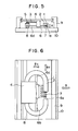
- FIG. 5 and 6 of the accompanying drawings show the construction of such vibration wave driven motor.
- the reference numeral 1 designates a resilient member having a projection 1a provided on the sliding surface side thereof, and a piezo-electric element 2 for forming a travelling vibration wave in the resilient member 1 is joined to the upper surface of the resilient member.
- the reference numeral 8 denotes a rail-like stator (a driven member) as a contact member which frictionally contacts with the resilient member 1.
- the rail-like stator 8 is brought into pressure contact with the resilient member 1 by a pressing spring 3 through a vibration insulating material 5 (for example, felt).
- the reference numeral 6 designates a comb-tooth-like movement stopper having its comb-tooth portion 6a inserted in a slit in that portion of the resilient member 1 which is not in contact with the rail-like stator 8.
- the comb-tooth portion 6a supports the resilient member 1 through felt 7 disposed on the bottom of the slit.
- the resilient member 1 is supported by a supporting table 4 through the movement stopper 6, the pressing spring 3, etc., and the supporting table 4 on which for example, the printing head of a printer is placed is supported by a restraining member 9 for restraining displacement in any other direction than a direction B Y which is a predetermined movement direction.
- the comb-tooth portion 6a of the movement stopper 6 is inserted in the slit portion of the resilient member 1 as shown in Figure 6, and restrains the displacement of the resilient member 1 in the direction B Y and also supports the weight of the resilient member 1 through the felt 7.
- Restraining portions 6b and 6c restrain the displacement of the resilient member 1 in the direction Bx
- a restraining member 6d restrains the displacement of the resilient member 1 on the pressed side thereof in the direction B Y .
- Figure 7 of the accompanying drawings is a perspective view of the resilient member 1 to which the piezo-electric element 2 is joined
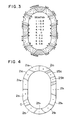
- Figures 8 and 9 of the accompanying drawings are contour maps showing the deviations of the surface of the piezo-electric element in two standing wave modes positionally deviating by 90° from each other and equal in resonance frequency which have been found by eigen value analysis using the finite element method.
- the deviation is a component in a direction perpendicular to the surface of the piezo-electric element, and the amount of deviation is maximum "1".
- This vibration member is such that fifteen waves are generated in the full circumference thereof and about five waves are generated in the straight portions thereof used for driving. Accordingly, the rail-like stator 8 and the resilient member 1 are in contact with each other at the antinodes of five waves.
- the travelling vibration wave generated in the resilient member 1 is irregular in the magnitude of amplitude from location to location because of the warp of the surfaces of the resilient member 1 and the piezo-electric element 2 and the non-uniformity of the materials thereof. Therefore, where the resilient member 1 and the rail-like stator 8 are in contact with each other at the antinodes of a number of waves, the states of contact in the individual waves differ and in an extreme case, the two members are in contact with each other at some locations and are not in contact with each other at other locations. This irregularity of contact has increased the slide loss on the sliding surface, has reduced the efficiency of the motor and has caused noise.
- the gist of the present invention for achieving the above objects resides in a vibration wave driven motor having a vibration member having an electro-mechanical energy conversion element secured to one surface of a resilient member of an elliptical annular shape formed by straight portions and arcuate portions, and a member brought into pressure contact with the other surface of said resilient member and wherein AC voltages having a phase difference of 90° therebetween in terms of time are applied to the driving phases of said electro-mechanical energy conversion element divided into two phases to thereby generate a travelling vibration wave in said resilient member, whereby said vibration member and said member brought into pressure contact therewith are moved relative to each other, characterized in that the two driving phases of said electro-mechanical energy conversion element are polarization-processed in such a manner that only one travelling wave is formed in the straight portions of said resilient member.
- Figures 1 to 4 show an embodiment of a vibration wave driven motor according to the present invention, Figure 1 being a perspective view of a vibration member, Figures 2 and 3 being contour maps of the deviation of the standing wave mode by the finite element method, Figure 4 showing the polarization pattern of the piezo-electric element thereof.
- Figures 5 and 6 are a side view and a plan view, respectively, of a vibration wave driven motor according to the prior art.
- Figure 7 is a perspective view of a vibration member according to the prior art.
- Figures 8 and 9 are contour maps of the deviation of two standing wave modes excited in the resilient member of Figure 7.
- Figures 10 and 11 are contour maps of the deviation of the standing wave mode in another embodiment of the present invention.
- Figures 1 to 4 schematically show the essential portions of a bubble jet type printer to which the present invention is applied.
- the other portions of the printer are identical in construction to those shown in Figures 5 and 6 and therefore are not shown.
- the bubble jet type printer is a printer as disclosed, for example, in U.S. Patent No. 4,723,129 or U.S. Patent No. 4,740,796.
- a printer of the type in which at least one driving signal corresponding to recording information and providing a rapid temperature rise exceeding nuleate boiling is applied to an electro-thermal conversion member diposed correspondingly to a sheet or a liquid path in which liquid (ink) is retained to thereby generate heat energy in the electro-thermal conversion member and cause film boiling on the heat-acting surface of a recording head, with a result that a bubble in the liquid (ink) is formed correspondingly to said driving signal and by the growth and contraction of this bubble, the liquid (ink) is discharged through a discharge opening to form at least one droplet, which is blown against a sheet to thereby form a character.
- the reference numeral 1 designates a resilient member formed into an elliptical annular shape.
- a piezo-electric element 2 as an electromechanical energy conversion element is adhesively secured to one surface of the resilient member 1, whereby a vibration member is constructed.
- the present embodiment is such that six travelling vibration waves are formed in the full circumference of the resilient member 1, and the polarization pattern of the piezo-electric element 2 is shown in Figure 4.
- the reference characters 2a1 and 2a2 denote the segment of the piezo-electric element which form one driving phase (hereinafter referred to as the A group) polarization-processed into the (+) polarity and the (-) polarity, respectively.
- These segments 2a1 and 2a2 of the piezo-electric element are disposed as shown in a positional phase difference of ⁇ /2 therebetween ( ⁇ being the wavelength of the vibration wave).
- the reference characters 2b1 and 2b2 designate the segments of the piezo-electric element which form the other driving phase (hereinafter referred to as the B group) polarization-processed into the (+) polarity and the (-) polarity, respectively.
- These segments 2b1 and 2b2 of the piezo-electric element are disposed as shown with a positional phase difference of ⁇ /2 therebetween.
- the A group and the B group are disposed with a positional deviation of ⁇ /4 therebetween.
- the polarization pattern shown in Figure 4 is such that in the A group, only one set of piezo-electric elements 2a1 and 2a2 are disposed for one straight portion of the resilient member 1 and in the B group as well, only one set of piezo-electric elements 2b1 and 2b2 are disposed for the other straight portion of the resilient member 1, whereby among the six travelling waves over the full circumference, only one travelling wave is formed in each straight portion.
- AC voltages which are equal in frequency and 90° out of phase with each other in terms of time are applied to the A group and the B group from a driving circuit, not shown, whereby travelling waves are formed on the resilient member 1, and the standing wave mode during the A group driving is shown in Figure 2 and the standing wave mode during the B group driving is shown in Figure 3.
- Figures 2 and 3 show the deviations of the respective standing wave modes in contour maps in the same manner as Figures 8 and 9.
- the length L of the straight portions is 7 mm and the average radius R of the arcuate portions (the average of the radius of the outer periphery and the radius of the inner periphery) is 5 mm in order to obtain the vibration modes shown in Figures 2 and 3, and by the inventor's experiment, it has been found that if the ratio (R/L) of the average radius R of the arcuate portions to the length L of the straight portions is 1/4 or more, the position of the maximum amplitude of the standing wave in the straight portions of the resilient member 1 exists on only one of the inner periphery side and the outer periphery side in both of the two vibration modes and when the vibration is made into a travelling wave, the amplitude on one of the outer periphery side and the inner periphery side is always high in the straight portions.
- one travelling wave formed on the straight portions of the resilient member 1 is higher in the amplitude on the outer periphery side. From this, in the case as shown, for example, in Figure 5, the outer periphery side of the resilient member 1 can be brought into pressure contact with the rail-like stator 8 to thereby drive the motor efficiently.
- the travelling wave formed on the resilient member 1 is such that only one wave is formed in the straight portions and therefore, if such resilient member is applied to the apparatus shown in Figure 5, the resilient member 1 and the rail-like stator 8 always contact with each other at the antinode of one wave without separating from each other and therefore, the reduction in the efficiency of the motor caused by the slide loss on the sliding surface can be decreased and at the same time, the generation of noise can be prevented.
- Figures 10 and 11 are contour maps of the deviations of the two standing wave modes of the resilient member 1 according to another embodiment of the present invention. This is seven waves over the full circumference, and approximately one wave is generated in the straight portions used for driving.
- the task can be achieved if the piezo-electric element is disposed so that irrespective of the number of waves over the full circumference, approximately one wave may be generated in the straight portions used for driving.
- the vibration member is moved and the stator 8 which is a portion of the printer is fixed in place, but alternatively, the vibration member may be fixed in place and the stator 8 may be moved to obtain a similar effect.
- such a travelling vibration wave that approximately one wave is created in the straight portions of the vibration member used for driving is generated and the vibration member and the member with which the vibration member is brought into pressure contact are always brought into contact with each other at the antinode of one wave without separating from each other, whereby the efficiency of the motor can be enhanced and noise can be prevented.
Landscapes
- General Electrical Machinery Utilizing Piezoelectricity, Electrostriction Or Magnetostriction (AREA)
Priority Applications (3)
| Application Number | Priority Date | Filing Date | Title |
|---|---|---|---|
| EP94200301A EP0598710B1 (fr) | 1989-12-08 | 1990-12-07 | Dispositf fonctionnant au moyen d'ondes vibratoires et imprimante du type à jet utilisant un tel dispositif |
| EP90313491A EP0437050B1 (fr) | 1989-12-12 | 1990-12-12 | Appareil actionné par ondes de vibration |
| DE69011651T DE69011651T2 (de) | 1989-12-12 | 1990-12-12 | Vibrationswellengetriebene Vorrichtung. |
Applications Claiming Priority (2)
| Application Number | Priority Date | Filing Date | Title |
|---|---|---|---|
| JP320127/89 | 1989-12-08 | ||
| JP1320127A JPH03183376A (ja) | 1989-12-08 | 1989-12-08 | 振動波モータ |
Related Child Applications (2)
| Application Number | Title | Priority Date | Filing Date |
|---|---|---|---|
| EP94200301A Division EP0598710B1 (fr) | 1989-12-08 | 1990-12-07 | Dispositf fonctionnant au moyen d'ondes vibratoires et imprimante du type à jet utilisant un tel dispositif |
| EP94200301.3 Division-Into | 1994-02-03 |
Publications (2)
| Publication Number | Publication Date |
|---|---|
| EP0435496A1 true EP0435496A1 (fr) | 1991-07-03 |
| EP0435496B1 EP0435496B1 (fr) | 1995-11-22 |
Family
ID=18118003
Family Applications (2)
| Application Number | Title | Priority Date | Filing Date |
|---|---|---|---|
| EP94200301A Expired - Lifetime EP0598710B1 (fr) | 1989-12-08 | 1990-12-07 | Dispositf fonctionnant au moyen d'ondes vibratoires et imprimante du type à jet utilisant un tel dispositif |
| EP90313324A Expired - Lifetime EP0435496B1 (fr) | 1989-12-08 | 1990-12-07 | Appareil actionné par ondes de vibration et imprimante du type à jet d'encre chauffé mettant en oeuvre un tel moteur |
Family Applications Before (1)
| Application Number | Title | Priority Date | Filing Date |
|---|---|---|---|
| EP94200301A Expired - Lifetime EP0598710B1 (fr) | 1989-12-08 | 1990-12-07 | Dispositf fonctionnant au moyen d'ondes vibratoires et imprimante du type à jet utilisant un tel dispositif |
Country Status (4)
| Country | Link |
|---|---|
| US (1) | US5155407A (fr) |
| EP (2) | EP0598710B1 (fr) |
| JP (1) | JPH03183376A (fr) |
| DE (2) | DE69023752T2 (fr) |
Cited By (4)
| Publication number | Priority date | Publication date | Assignee | Title |
|---|---|---|---|---|
| EP0600485A1 (fr) * | 1992-12-03 | 1994-06-08 | Canon Kabushiki Kaisha | Dispositif de support pour organe d'actionnement à vibrations |
| EP0607980A1 (fr) * | 1993-01-22 | 1994-07-27 | Canon Kabushiki Kaisha | Moteur actionné par des ondes vibratoires et appareil d'impression |
| AP447A (en) * | 1993-01-08 | 1996-01-17 | Mul T Lock Ltd | Locking apparatus. |
| US5583390A (en) * | 1989-12-12 | 1996-12-10 | Canon Kabushiki Kaisha | Vibration wave driven apparatus |
Families Citing this family (16)
| Publication number | Priority date | Publication date | Assignee | Title |
|---|---|---|---|---|
| US5428260A (en) * | 1990-08-03 | 1995-06-27 | Canon Kabushiki Kaisha | Vibration driven motor |
| JPH0564467A (ja) * | 1991-09-05 | 1993-03-12 | Canon Inc | 振動波リニアモーター |
| JPH05116788A (ja) * | 1991-10-29 | 1993-05-14 | Canon Inc | シート送り装置 |
| JPH066986A (ja) * | 1992-06-17 | 1994-01-14 | Canon Inc | 振動波モーター及びその製造方法 |
| US6628046B2 (en) | 1997-05-27 | 2003-09-30 | Canon Kabushiki Kaisha | Vibration type actuator |
| US6404104B1 (en) | 1997-11-27 | 2002-06-11 | Canon Kabushiki Kaisha | Vibration type actuator and vibration type driving apparatus |
| JP4328412B2 (ja) | 1999-05-14 | 2009-09-09 | キヤノン株式会社 | 振動型アクチュエータおよび振動型駆動装置 |
| JP4726167B2 (ja) * | 2001-03-12 | 2011-07-20 | キヤノン株式会社 | 振動波駆動装置 |
| JP4731723B2 (ja) * | 2001-05-24 | 2011-07-27 | キヤノン株式会社 | 振動波駆動装置の製造方法 |
| JP4027090B2 (ja) * | 2001-12-27 | 2007-12-26 | キヤノン株式会社 | 振動体および振動波駆動装置 |
| JP4756916B2 (ja) * | 2005-05-31 | 2011-08-24 | キヤノン株式会社 | 振動波モータ |
| DE102012022146A1 (de) | 2012-11-12 | 2014-05-15 | Physik Instrumente (Pi) Gmbh & Co. Kg | Ultraschallaktor für einen linearen Ultraschallmotor sowie linearer Ultraschallmotor mit einem Ultraschallaktor |
| US10516091B2 (en) | 2015-11-27 | 2019-12-24 | Canon Kabushiki Kaisha | Ultrasonic motor, drive control system, optical apparatus, and vibrator |
| US10451833B2 (en) | 2015-11-27 | 2019-10-22 | Canon Kabushiki Kaisha | Ultrasonic motor, drive control system, optical apparatus, and vibrator |
| US10536097B2 (en) | 2015-11-27 | 2020-01-14 | Canon Kabushiki Kaisha | Ultrasonic motor, drive control system, optical apparatus, and vibrator |
| US10775681B2 (en) | 2015-11-27 | 2020-09-15 | Canon Kabushiki Kaisha | Ultrasonic motor, drive control system, optical apparatus, and vibrator |
Citations (3)
| Publication number | Priority date | Publication date | Assignee | Title |
|---|---|---|---|---|
| EP0169297A2 (fr) * | 1984-03-01 | 1986-01-29 | Matsushita Electric Industrial Co., Ltd. | Moteur piézoélectrique |
| US4672256A (en) * | 1984-12-26 | 1987-06-09 | Canon Kabushiki Kaisha | Linear vibration wave motor |
| EP0301430A2 (fr) * | 1987-07-26 | 1989-02-01 | Honda Electronic Co., Ltd. | Dispositif de commande ultrasonique |
Family Cites Families (15)
| Publication number | Priority date | Publication date | Assignee | Title |
|---|---|---|---|---|
| CA1127227A (fr) * | 1977-10-03 | 1982-07-06 | Ichiro Endo | Procede d'enregistrement a jet liquide et appareil d'enregistrement |
| JPS59201685A (ja) * | 1983-04-30 | 1984-11-15 | Canon Inc | 振動波モ−タ |
| JPS6046781A (ja) * | 1983-08-24 | 1985-03-13 | Canon Inc | 振動波モ−タ |
| JPS6118371A (ja) * | 1984-07-03 | 1986-01-27 | Matsushita Electric Ind Co Ltd | 圧電モ−タ |
| US4692652A (en) * | 1985-03-29 | 1987-09-08 | Canon Kabushiki Kaisha | Vibration wave motor |
| JPS61224880A (ja) * | 1985-03-29 | 1986-10-06 | Canon Inc | 振動波モ−タ |
| JPS6277969A (ja) * | 1985-10-02 | 1987-04-10 | Nec Corp | プリンタ装置 |
| JPS6277968A (ja) * | 1985-10-02 | 1987-04-10 | Nec Corp | プリンタ装置 |
| DE3876326T2 (de) * | 1987-02-02 | 1993-05-13 | Hitachi Ltd | Tragbares dosimeter sowie dessen verwendung bei einem geraet zur kontrolle intensiver strahlungsaussetzung. |
| JPS63213480A (ja) * | 1987-02-27 | 1988-09-06 | Nec Corp | 超音波モ−タ |
| JPS63294273A (ja) * | 1987-05-25 | 1988-11-30 | Jgc Corp | 超音波駆動装置 |
| JPS6417669A (en) * | 1987-12-03 | 1989-01-20 | Nitta Kk | Glasses for golf exercise |
| JPH0268465A (ja) * | 1988-08-31 | 1990-03-07 | Shirakawa Shiro | 冷却ならびに、加熱装置 |
| JPH02285974A (ja) * | 1989-04-25 | 1990-11-26 | Canon Inc | 振動波モータ |
| JPH0321879A (ja) * | 1989-06-20 | 1991-01-30 | Hitachi Electron Eng Co Ltd | テスターのタイミング信号発生回路 |
-
1989
- 1989-12-08 JP JP1320127A patent/JPH03183376A/ja active Pending
-
1990
- 1990-12-07 US US07/623,571 patent/US5155407A/en not_active Expired - Fee Related
- 1990-12-07 EP EP94200301A patent/EP0598710B1/fr not_active Expired - Lifetime
- 1990-12-07 DE DE69023752T patent/DE69023752T2/de not_active Expired - Fee Related
- 1990-12-07 EP EP90313324A patent/EP0435496B1/fr not_active Expired - Lifetime
- 1990-12-07 DE DE69032138T patent/DE69032138T2/de not_active Expired - Fee Related
Patent Citations (3)
| Publication number | Priority date | Publication date | Assignee | Title |
|---|---|---|---|---|
| EP0169297A2 (fr) * | 1984-03-01 | 1986-01-29 | Matsushita Electric Industrial Co., Ltd. | Moteur piézoélectrique |
| US4672256A (en) * | 1984-12-26 | 1987-06-09 | Canon Kabushiki Kaisha | Linear vibration wave motor |
| EP0301430A2 (fr) * | 1987-07-26 | 1989-02-01 | Honda Electronic Co., Ltd. | Dispositif de commande ultrasonique |
Non-Patent Citations (2)
| Title |
|---|
| PATENT ABSTRACTS OF JAPAN vol. 11, no. 278 (M-623), 9 September 1987; & JP - A - 62077968 (NEC) 10.04.1987 * |
| PATENT ABSTRACTS OF JAPAN vol. 9, no. 173 (E-329)(1896), 18 July 1985; & JP - A - 60046781 (CANON) 13.03.1985 * |
Cited By (6)
| Publication number | Priority date | Publication date | Assignee | Title |
|---|---|---|---|---|
| US5583390A (en) * | 1989-12-12 | 1996-12-10 | Canon Kabushiki Kaisha | Vibration wave driven apparatus |
| EP0600485A1 (fr) * | 1992-12-03 | 1994-06-08 | Canon Kabushiki Kaisha | Dispositif de support pour organe d'actionnement à vibrations |
| US5484216A (en) * | 1992-12-03 | 1996-01-16 | Canon Kabushiki Kaisha | Supporting device for a vibration driven actuator |
| AP447A (en) * | 1993-01-08 | 1996-01-17 | Mul T Lock Ltd | Locking apparatus. |
| EP0607980A1 (fr) * | 1993-01-22 | 1994-07-27 | Canon Kabushiki Kaisha | Moteur actionné par des ondes vibratoires et appareil d'impression |
| US5945771A (en) * | 1993-01-22 | 1999-08-31 | Canon Kabushiki Kaisha | Vibration wave driven motor and a printing apparatus |
Also Published As
| Publication number | Publication date |
|---|---|
| EP0598710A3 (fr) | 1994-11-02 |
| EP0598710A2 (fr) | 1994-05-25 |
| JPH03183376A (ja) | 1991-08-09 |
| US5155407A (en) | 1992-10-13 |
| EP0598710B1 (fr) | 1998-03-11 |
| DE69023752D1 (de) | 1996-01-04 |
| DE69023752T2 (de) | 1996-05-02 |
| DE69032138T2 (de) | 1998-07-30 |
| EP0435496B1 (fr) | 1995-11-22 |
| DE69032138D1 (de) | 1998-04-16 |
Similar Documents
| Publication | Publication Date | Title |
|---|---|---|
| US5155407A (en) | Vibration driven apparatus | |
| US4580073A (en) | Vibration wave motor with plural projection vibrator | |
| US7109639B2 (en) | Vibration-type driving device, control apparatus for controlling the driving of the vibration-type driving device, and electronic equipment having the vibration-type driving device and the control apparatus | |
| US5039899A (en) | Piezoelectric transducer | |
| EP0440491B1 (fr) | Moteur entraîné par onde de vibration | |
| US4587452A (en) | Vibration wave motor having a vibrator of non-uniform elastic modulus | |
| US4692652A (en) | Vibration wave motor | |
| EP0450919B1 (fr) | Moteur actionné par ondes vibratoires | |
| JPH0389875A (ja) | リニア超音波モータ | |
| US5583390A (en) | Vibration wave driven apparatus | |
| US5274294A (en) | Vibration wave driven motor | |
| US5041750A (en) | Vibration wave driven apparatus | |
| EP0530822B1 (fr) | Dispositif de guidage pour moteur à ondes vibratoires | |
| US5455478A (en) | Vibration wave driven apparatus | |
| US5176376A (en) | Vibration sheet feeder | |
| JPS61224880A (ja) | 振動波モ−タ | |
| EP0404158B1 (fr) | Dispositif d'alimentation de feuilles | |
| EP0406807A2 (fr) | Dispositif d'alimentation en feuilles | |
| JPH06121554A (ja) | 超音波モータ | |
| JPH09117166A (ja) | 超音波モータ | |
| JPS63136983A (ja) | 振動波モ−タ | |
| JPH0552137B2 (fr) | ||
| JP2005102368A (ja) | 駆動装置 | |
| JPS63117674A (ja) | 超音波モ−タ | |
| JPH04317574A (ja) | 超音波モータ |
Legal Events
| Date | Code | Title | Description |
|---|---|---|---|
| PUAI | Public reference made under article 153(3) epc to a published international application that has entered the european phase |
Free format text: ORIGINAL CODE: 0009012 |
|
| 17P | Request for examination filed |
Effective date: 19901231 |
|
| AK | Designated contracting states |
Kind code of ref document: A1 Designated state(s): DE FR GB IT NL |
|
| 17Q | First examination report despatched |
Effective date: 19920928 |
|
| GRAA | (expected) grant |
Free format text: ORIGINAL CODE: 0009210 |
|
| AK | Designated contracting states |
Kind code of ref document: B1 Designated state(s): DE FR GB IT NL |
|
| XX | Miscellaneous (additional remarks) |
Free format text: TEILANMELDUNG 94200301.3 EINGEREICHT AM 07/12/90. |
|
| REF | Corresponds to: |
Ref document number: 69023752 Country of ref document: DE Date of ref document: 19960104 |
|
| ET | Fr: translation filed | ||
| ITF | It: translation for a ep patent filed | ||
| PLBE | No opposition filed within time limit |
Free format text: ORIGINAL CODE: 0009261 |
|
| STAA | Information on the status of an ep patent application or granted ep patent |
Free format text: STATUS: NO OPPOSITION FILED WITHIN TIME LIMIT |
|
| 26N | No opposition filed | ||
| REG | Reference to a national code |
Ref country code: GB Ref legal event code: IF02 |
|
| PGFP | Annual fee paid to national office [announced via postgrant information from national office to epo] |
Ref country code: GB Payment date: 20031124 Year of fee payment: 14 |
|
| PGFP | Annual fee paid to national office [announced via postgrant information from national office to epo] |
Ref country code: NL Payment date: 20031215 Year of fee payment: 14 |
|
| PGFP | Annual fee paid to national office [announced via postgrant information from national office to epo] |
Ref country code: FR Payment date: 20031222 Year of fee payment: 14 |
|
| PGFP | Annual fee paid to national office [announced via postgrant information from national office to epo] |
Ref country code: DE Payment date: 20031223 Year of fee payment: 14 |
|
| PG25 | Lapsed in a contracting state [announced via postgrant information from national office to epo] |
Ref country code: GB Free format text: LAPSE BECAUSE OF NON-PAYMENT OF DUE FEES Effective date: 20041207 |
|
| PG25 | Lapsed in a contracting state [announced via postgrant information from national office to epo] |
Ref country code: NL Free format text: LAPSE BECAUSE OF NON-PAYMENT OF DUE FEES Effective date: 20050701 Ref country code: DE Free format text: LAPSE BECAUSE OF NON-PAYMENT OF DUE FEES Effective date: 20050701 |
|
| GBPC | Gb: european patent ceased through non-payment of renewal fee |
Effective date: 20041207 |
|
| PG25 | Lapsed in a contracting state [announced via postgrant information from national office to epo] |
Ref country code: FR Free format text: LAPSE BECAUSE OF NON-PAYMENT OF DUE FEES Effective date: 20050831 |
|
| NLV4 | Nl: lapsed or anulled due to non-payment of the annual fee |
Effective date: 20050701 |
|
| REG | Reference to a national code |
Ref country code: FR Ref legal event code: ST |
|
| PG25 | Lapsed in a contracting state [announced via postgrant information from national office to epo] |
Ref country code: IT Free format text: LAPSE BECAUSE OF NON-PAYMENT OF DUE FEES;WARNING: LAPSES OF ITALIAN PATENTS WITH EFFECTIVE DATE BEFORE 2007 MAY HAVE OCCURRED AT ANY TIME BEFORE 2007. THE CORRECT EFFECTIVE DATE MAY BE DIFFERENT FROM THE ONE RECORDED. Effective date: 20051207 |