EP0439988A2 - Contrôle d'options installées par ordinateur - Google Patents
Contrôle d'options installées par ordinateur Download PDFInfo
- Publication number
- EP0439988A2 EP0439988A2 EP90480223A EP90480223A EP0439988A2 EP 0439988 A2 EP0439988 A2 EP 0439988A2 EP 90480223 A EP90480223 A EP 90480223A EP 90480223 A EP90480223 A EP 90480223A EP 0439988 A2 EP0439988 A2 EP 0439988A2
- Authority
- EP
- European Patent Office
- Prior art keywords
- status
- computer system
- memory
- ram
- additional devices
- Prior art date
- Legal status (The legal status is an assumption and is not a legal conclusion. Google has not performed a legal analysis and makes no representation as to the accuracy of the status listed.)
- Withdrawn
Links
Images



Classifications
-
- G—PHYSICS
- G06—COMPUTING OR CALCULATING; COUNTING
- G06F—ELECTRIC DIGITAL DATA PROCESSING
- G06F9/00—Arrangements for program control, e.g. control units
- G06F9/06—Arrangements for program control, e.g. control units using stored programs, i.e. using an internal store of processing equipment to receive or retain programs
- G06F9/44—Arrangements for executing specific programs
- G06F9/4401—Bootstrapping
- G06F9/4411—Configuring for operating with peripheral devices; Loading of device drivers
-
- G—PHYSICS
- G06—COMPUTING OR CALCULATING; COUNTING
- G06F—ELECTRIC DIGITAL DATA PROCESSING
- G06F15/00—Digital computers in general; Data processing equipment in general
- G06F15/16—Combinations of two or more digital computers each having at least an arithmetic unit, a program unit and a register, e.g. for a simultaneous processing of several programs
- G06F15/177—Initialisation or configuration control
Definitions
- This invention relates to computers which monitor their physical status and signal that status to persons operating the computer. More specifically, installed optional features are monitored and their subsequent status is signaled.
- Computer monitoring of installed features at turn-on of the computer is standard. Typically, such computers automatically send signals unique to each possible installed feature and monitor for a unique response. Receipt of the response is interpreted as the feature being installed and operative. Typically, also, the computer operator may call up or is automatically presented with a list of such features found installed and operative.
- POST power-on self test
- POST is run when power is first applied to the machine and when initialization is called for by a predetermined keyboard entry (often the simultaneous keying of the keys labeled: Alt, Del, Ctrl) (standing for Alternate, Delete and Control). If the device is partially working, then an error is reported. If the device is totally non-functional, then for some devices no error is reported because the device is an option and simply may not be attached.
- CMOS complementary metal oxide semiconductor
- IBM Technical Disclosure Bulletin article "Resolution of Missing Hardware Options,” Vol. 31, No. 12, May 1989, pp. 361-363 teaches using non-volatile memory in an options tracking system in which the fact of previous operable addition of an option is stored and compared with the current status of that option, but involving extensive operator participation.
- Heath et al applicant International Business Machines Corp. teaches using non-volatile memory to store an identity value and card parameter data for option cards inserted in a computer.
- the memory is of the CMOS type, which is the same as that used in the preferred embodiment of this invention.
- This invention also comprises a computer with a display of installed options, the installation of an option being monitored by the computer at each start-up of the computer by exercising the option. The presence of each option is recorded in memory. At each start-up the current options are compared with those in memory and those options which are shown as added by the memory but are not currently found to be installed are displayed with emphasis to indicate that. This brings the possibility of a non-functioning option to the attention of the computer operator.
- Fig. 1 is illustrative of a computer in accordance with this invention with options which may be installed;
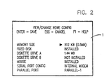
- Fig. 2 illustrates a display emphasizing an option which the monitoring shows has changed from the previous installation;
- Fig. 3a and Fig. 3b illustrate the sequence of operations to determine the status of features, and
- Fig. 4 illustrates the sequence of operations to revise or not revise the memory listing of features installed.
- the preferred system is a personal computer having a display 1, which can be a basically conventional cathode ray tube (CRT) display.
- the personal computer has a system unit 3 which contains a microprocessor 5, read only memory 7, and random access memory 9, which is at least partially powered by both system electrical power from a wall plug and a battery which functions to maintain information in the absence of the system power.
- Read only memory 7 contains all of the permanent control information, including a POST which is largely conventional and widely employed, but contains oparations as here described to signal the status of options.
- a disk drive 11 may receive a single external diskette or may be internal and operate off a built-in disk memory, commonly termed a fixed or "hard" disk.
- the disk drive 11 of the preferred embodiment specifically may constitute two diskette drives for external diskettes or a single diskette drive and a fixed disk drive, either of which configurations are commonly found.
- Command signals and information signals are entered into system unit 3 by a human operator through keyboard 15 or mouse 16. Except for the changes in POST to monitor options, as will be described in detail below, the foregoing combination of a system unit 3 with microprocessor 5, ROM 7, RAM 9, disk drive 11, and entry devices 15 and 16 is conventional in personal computers and therefore will not be described in further detail.
- Fig. 1 Also shown in Fig. 1 are devices 17 and 19 in system unit 3. These are optional features (options) which may or may not be added to the computer. Typically they are mounted on circuit boards and are installed by being plugged in electrically. Expansion unit 20 is added when options are to be installed which do not fit in system unit 3. Expansion unit 20 rests upon and is electrically connected to system unit 3, and options 21 and 23 may be installed in expansion unit 20. Options 21 and 23 then function in response to signals from system unit 3 in the same manner as options 17 and 19.
- the POST is initiated and addresses each possible option. All options are installed to be addressed electrically by system unit 3 on a single set of parallel signal lines, commonly known as the address bus. Similarly, all options are installed to provide signals to system unit 3 on another single set of parallel signal lines, commonly known as the data bus. In this preferred embodiment the status of each possible option is determined by POST placing unique signals on the address bus, with the proper response signals on the data bus constituting information that an option is in the computer and is operable. With the exception of those for the game option, the commands sent and responses monitored for are virtually identical or essentially the same as in previous systems.
- the game option has sound capabilities and directional "joy stick" input capabilities suitable for playing computer games.
- Details of the POST signals and responses for this monitoring are as follows: Display - Write and read display adapter registers; Write and read Display adapter memory. Keyboard - Command reset; Receive reset complete. Mouse - Command reset; Receive reset complete. Serial Port - Write and read at known addresses. Internal Modem - Send setup command; Receive setup-complete response. Parallel Port - Write and read at known addresses.
- Memory Determine memory size by writing and reading memory locations at 64 K byte boundaries; first incorrect response indicating memory size; Write and read bit patterns in all memory locations within the determined memory size to verify correct function.
- Diskette Drive A Command move head to track zero; Receive head at track zero; Command move head away from track zero; Receive head not at track zero.
- Diskette Drive B Command move head to track zero; Receive head at track zero; Command move head away from track zero; Receive head not at track zero; Check continuity on two lines (lines installed only when this feature is installed). Fixed disk - Write command; Check fixed disk control line low; Command reset; Receive reset complete. Game - Write predetermined pattern of data to first-in-first-out (FIFO) buffer register until full; Receive information written by writing further zeros to FIFO until empty.
- FIFO first-in-first-out
- time-out failure to receive the response before time-out is interpreted as the option not being installed, proper installation therefore requiring not only physical presence of the option, but its proper functioning.
- Fig. 2 is a display 1 message showing the options in the preferred embodiment as found by the POST monitoring.
- the black arrowhead pointing to the memory size provides the emphasis mark. It appears because the immediately preceding status of installation found by the POST monitoring had more memory than the 512 KB shown in this screen.
- screen of Fig. 2 is not shown unless it is called for by an entry from keyboard 15 or mouse 16 calling for it.
- the POST will produce a message on the screen that a configuration error appears or, alternatively, could automatically bring up the screen of Fig. 2.
- Fig. 3a and Fig. 3b are illustrative of the sequence of operations to effectuate the foregoing.
- POST 30 begins the feature monitoring by interrogating for display 1 at action 32 as described and comparing that status with the status for display 1 stored in RAM 9. If the installed status is the same, the sequence moves to monitor the next feature. If the installed status is different, this is determined to be a reduction or addition in action 34 with respect to the prior installed status for display 1 stored in RAM 9. A reduced status results in an emphasize signal 36 (commonly termed a flag) being stored in RAM 9. An addition determination results in that new status being stored in RAM 9 in place of the information for the previous status for display 1.
- Keyboard 15 is then monitored by interrogating for keyboard 15 at action 38 as described and comparing that status with the status for keyboard 15 stored in RAM 9. If the installed status is the same, the sequence moves to monitor the next feature. If the installed status is different, this is determined to be a reduction or addition in action 40 with respect to the prior installed status for keyboard 15 stored in RAM 9. A reduced status results in an emphasize signal 42 being stored in RAM 9. An addition determination results in that new status being stored in RAM 9 in place of the information for the previous status for keyboard 15.
- Mouse 16 is then monitored by interrogating for mouse 16 at action 44 as described and comparing that status with the status for mouse 16 stored in RAM 9. If the installed status is the same, the sequence moves to monitor the next feature. If the installed status is different, this is determined to be a reduction or addition in action 46 with respect to the prior installed status for mouse 16 stored in RAM 9. A reduced status results in an emphasize signal 48 being stored in RAM 9. An addition determination results in that new status being stored in RAM 9 in place of the information for the previous status for mouse 16.
- serial port is then monitored by interrogating for the serial port at action 50 as described and comparing that status with the status for the serial port stored in RAM 9. If the installed status is the same, the sequence moves to monitor the next feature. If the installed status is different, this is determined to be a reduction or addition in action 52 with respect to the prior installed status for the serial port stored in RAM 9. A reduced status results in an emphasize signal 54 being stored in RAM 9. An addition determination results in that new status being stored in RAM 9 in place of the information for the previous status for the serial port.
- the modem is then monitored by interrogating for the modem at action 56 as described and comparing that status with the status for the modem stored in RAM 9. If the installed status is the same, the sequence moves to monitor the next feature. If the installed status is different, this is determined to be a reduction or addition in action 58 with respect to the prior installed status for the modem stored in RAM 9. A reduced status results in an emphasize signal 60 being stored in RAM 9. An addition determination results in that new status being stored in RAM 9 in place of the information for the previous status for the modem.
- the parallel port is then monitored (Fig. 3b) by interrogating for the parallel port at action 62 as described and comparing that status with the status for the parallel port stored in RAM 9. If the installed status is the same, the sequence moves to monitor the next feature. If the installed status is different, this is determined to be a reduction or addition in action 64 with respect to the prior installed status for the parallel port in RAM 9. A reduced status results in an emphasize signal 66 being stored in RAM 9. An addition determination results in that new status being stored in RAM 9 in place of the information for the previous status for the parallel port.
- Memory is then monitored by interrogating for the memory at action 68 as described and comparing that status with the status for the memory stored in RAM 9. If the installed status is the same, the sequence moves to monitor the next feature. If the installed status is different, this is determined to be a reduction or addition in action 70 with respect to the prior installed status for the parallel port in RAM 9. A reduced status results in an emphasize signal 72 being stored in RAM 9. An addition determination results in that new status being stored in RAM 9 in place of the information for the previous status for memory.
- Drive A is then monitored by interrogating for Drive A at action 74 as described and comparing that status with the status for Drive A stored in RAM 9. If the installed status is the same, the sequence moves to monitor the next feature. If the installed status is different, this is determined to be a reduction or addition in action 76 with respect to the prior installed status for Drive A in RAM 9. A reduced status results in an emphasize signal 78 being stored in RAM 9. An addition determination results in that new status being stored in RAM 9 in place of the information for the previous status for Drive A.
- Drive B is then monitored by interrogating for Drive B at action 80 as described and comparing that status with the status for Drive B stored in RAM 9. If the installed status is the same, the sequence moves to monitor the next feature. If the installed status is different, this is determined to be a reduction or addition in action 82 with respect to the prior installed status for Drive B in RAM 9. A reduced status results in an emphasize signal 84 being stored in RAM 9. An addition determination results in that new status being stored in RAM 9 in place of the information for the previous status for Drive B.
- Fixed disk is then monitored by interrogating for fixed disk at action 86 as described and comparing that status with the status for fixed disk stored in RAM 9. If the installed status is the same, the sequence moves to monitor the next feature. If the installed status is different, this is determined to be a reduction or addition in action 88 with respect to the prior installed status for fixed disk in RAM 9. A reduced status results in an emphasize signal 90 being stored in RAM 9. An addition determination results in that new status being stored in RAM 9 in place of the information for the previous status for fixed disk.
- the game card is then monitored by interrogating for the game card at action 92 as described and comparing that status with the status for the game card stored in RAM 9. If the installed status is the same, the sequence moves to the remainder of POST 30. If the installed status is different, this is determined to be a reduction or addition in action 94 with respect to the prior installed status for fixed disk in RAM 9. A reduced status results in an emphasize signal 96 being stored in RAM 9. An addition determination results in that new status being stored in RAM 9 in place of the information for the previous status for the game card. The sequence then returns at action 94 to the remainder of POST 30.
- Each of the yes determinations stored in RAM 9 also is employed to produce an error signal displayed at the end of POST 30 on display 1. That is a standard procedure to show such errors at turn on, and the messages displayed are the number code unique to each feature which is also standard in such error messages. The operator must then activate a preselected key on keyboard 15 to terminate the error signal and continue with normal start-up. Normal start-up is terminated with a selection screen on display 1. Selection of disk operation system while that screen is displayed permits an optional input which calls up the listing of features on display 1 shown in Fig. 2. On that message on display 1, the emphasize signals stored in RAM 9 results a black arrowhead pointing to each feature found to be reduced, shown in Fig. 2 by the black arrowhead pointed to memory size.
- the message display of Fig. 2 is terminated by entering either Enter from keyboard 15 or by mouse 16 or Esc from the corresponding key of keyboard 15 or by mouse 16.
Landscapes
- Engineering & Computer Science (AREA)
- Software Systems (AREA)
- Theoretical Computer Science (AREA)
- Computer Hardware Design (AREA)
- Physics & Mathematics (AREA)
- General Engineering & Computer Science (AREA)
- General Physics & Mathematics (AREA)
- Computer Security & Cryptography (AREA)
- Debugging And Monitoring (AREA)
Applications Claiming Priority (2)
| Application Number | Priority Date | Filing Date | Title |
|---|---|---|---|
| US47443390A | 1990-02-02 | 1990-02-02 | |
| US474433 | 1990-02-02 |
Publications (2)
| Publication Number | Publication Date |
|---|---|
| EP0439988A2 true EP0439988A2 (fr) | 1991-08-07 |
| EP0439988A3 EP0439988A3 (en) | 1992-07-22 |
Family
ID=23883512
Family Applications (1)
| Application Number | Title | Priority Date | Filing Date |
|---|---|---|---|
| EP19900480223 Withdrawn EP0439988A3 (en) | 1990-02-02 | 1990-12-28 | Computer monitoring of installed options |
Country Status (2)
| Country | Link |
|---|---|
| EP (1) | EP0439988A3 (fr) |
| JP (1) | JPH0776952B2 (fr) |
Cited By (4)
| Publication number | Priority date | Publication date | Assignee | Title |
|---|---|---|---|---|
| DE9215701U1 (de) * | 1992-11-19 | 1993-01-07 | Wissing, Heimo, Dr.med. Dipl.-Ing., 6900 Heidelberg | Vorrichtung zum Anschluß von Bildschirmen an Personal-Computer |
| DE4244266A1 (fr) * | 1991-12-27 | 1993-07-01 | Intel Corp | |
| EP0684556A1 (fr) * | 1994-05-17 | 1995-11-29 | International Business Machines Corporation | Système de traitement d'information |
| EP1353268A1 (fr) * | 2002-04-11 | 2003-10-15 | Hewlett-Packard Company | Système pour afficher des informations pendant le démarrage du système |
Family Cites Families (5)
| Publication number | Priority date | Publication date | Assignee | Title |
|---|---|---|---|---|
| US4334307A (en) * | 1979-12-28 | 1982-06-08 | Honeywell Information Systems Inc. | Data processing system with self testing and configuration mapping capability |
| JPS59177628A (ja) * | 1983-03-28 | 1984-10-08 | Nec Corp | バス制御回路 |
| JPS61141001A (ja) * | 1984-12-14 | 1986-06-28 | Fuji Electric Co Ltd | プロセス制御システムの系構成診断方式 |
| GB8725111D0 (en) * | 1987-03-13 | 1987-12-02 | Ibm | Data processing system |
| GB2202062B (en) * | 1987-03-14 | 1991-05-01 | Plessey Co Plc | Apparatus for checking a system configuration |
-
1990
- 1990-12-20 JP JP2411856A patent/JPH0776952B2/ja not_active Expired - Lifetime
- 1990-12-28 EP EP19900480223 patent/EP0439988A3/en not_active Withdrawn
Cited By (4)
| Publication number | Priority date | Publication date | Assignee | Title |
|---|---|---|---|---|
| DE4244266A1 (fr) * | 1991-12-27 | 1993-07-01 | Intel Corp | |
| DE9215701U1 (de) * | 1992-11-19 | 1993-01-07 | Wissing, Heimo, Dr.med. Dipl.-Ing., 6900 Heidelberg | Vorrichtung zum Anschluß von Bildschirmen an Personal-Computer |
| EP0684556A1 (fr) * | 1994-05-17 | 1995-11-29 | International Business Machines Corporation | Système de traitement d'information |
| EP1353268A1 (fr) * | 2002-04-11 | 2003-10-15 | Hewlett-Packard Company | Système pour afficher des informations pendant le démarrage du système |
Also Published As
| Publication number | Publication date |
|---|---|
| JPH0418653A (ja) | 1992-01-22 |
| JPH0776952B2 (ja) | 1995-08-16 |
| EP0439988A3 (en) | 1992-07-22 |
Similar Documents
| Publication | Publication Date | Title |
|---|---|---|
| CA2046356C (fr) | Methode et dispositif pour ameliorer l'initialisation des fonctions d'un ordinateur | |
| US5987536A (en) | Computer system having flash memory bios which can be accessed while protected mode operating system is running | |
| US6513114B1 (en) | System and methods for providing selectable initialization sequences | |
| JPH0740701B2 (ja) | デ−タ出力装置 | |
| US5832285A (en) | Battery powered computer capable of switching to a suspend mode based on the connection status of an external device | |
| JPH09120385A (ja) | コンピュータシステムにおけるスタンバイ中のデバイス構成のロス防止方法およびデバイス構成の捕捉のためのコントローラ回路 | |
| US20030075599A1 (en) | Personal work environment setting method | |
| US10013172B2 (en) | Electronic data storage device with multiple configurable data storage mediums | |
| EP0439988A2 (fr) | Contrôle d'options installées par ordinateur | |
| EP1560154B1 (fr) | Système récréatif, unité de traitement d'information et mémoire portable | |
| US20020083221A1 (en) | Universal disk array controller | |
| US6722572B2 (en) | Recording medium control method, data management apparatus, and recording medium | |
| US6760788B2 (en) | Domain validation process that is transparent to a device driver | |
| JP3104685B2 (ja) | システムログ記録装置、システムログ記録方法および記録媒体 | |
| JP6856884B1 (ja) | 情報処理システム、情報処理装置およびプログラム | |
| CA2140963C (fr) | Transfert rapide de donnees d'entree-sortie a base de drapeaux | |
| EP0217348B1 (fr) | Circuit de détection de l'état connecté d'une mémoire | |
| EP0556138A1 (fr) | Bus pour la connexion de cartes d'extension à un système de traitement de données et procédé de test | |
| EP0661632A1 (fr) | Chargement de systèmes d'exploitation dans les ordinateurs | |
| JPS63268085A (ja) | 携帯可能記憶媒体読取書込装置 | |
| JPH0744280A (ja) | 情報処理システム | |
| JP2861673B2 (ja) | Rom読取制御装置 | |
| JPH0264726A (ja) | 外部メモリ装置を接続する情報処理装置 | |
| JPH03105402A (ja) | 外部記憶装置を利用可能な電子機器 | |
| CN114385379A (zh) | 板载信息刷写检测方法、系统、终端及存储介质 |
Legal Events
| Date | Code | Title | Description |
|---|---|---|---|
| PUAI | Public reference made under article 153(3) epc to a published international application that has entered the european phase |
Free format text: ORIGINAL CODE: 0009012 |
|
| AK | Designated contracting states |
Kind code of ref document: A2 Designated state(s): DE FR GB |
|
| 17P | Request for examination filed |
Effective date: 19911211 |
|
| PUAL | Search report despatched |
Free format text: ORIGINAL CODE: 0009013 |
|
| AK | Designated contracting states |
Kind code of ref document: A3 Designated state(s): DE FR GB |
|
| 17Q | First examination report despatched |
Effective date: 19950324 |
|
| STAA | Information on the status of an ep patent application or granted ep patent |
Free format text: STATUS: THE APPLICATION IS DEEMED TO BE WITHDRAWN |
|
| 18D | Application deemed to be withdrawn |
Effective date: 19951005 |